WO2012111228A1 - Caches inférieurs pour carrosserie de véhicule - Google Patents
Caches inférieurs pour carrosserie de véhicule Download PDFInfo
- Publication number
- WO2012111228A1 WO2012111228A1 PCT/JP2011/078883 JP2011078883W WO2012111228A1 WO 2012111228 A1 WO2012111228 A1 WO 2012111228A1 JP 2011078883 W JP2011078883 W JP 2011078883W WO 2012111228 A1 WO2012111228 A1 WO 2012111228A1
- Authority
- WO
- WIPO (PCT)
- Prior art keywords
- undercover
- vehicle body
- vehicle
- floor
- rear wheel
- Prior art date
- Legal status (The legal status is an assumption and is not a legal conclusion. Google has not performed a legal analysis and makes no representation as to the accuracy of the status listed.)
- Ceased
Links
Images


Classifications
-
- B—PERFORMING OPERATIONS; TRANSPORTING
- B62—LAND VEHICLES FOR TRAVELLING OTHERWISE THAN ON RAILS
- B62D—MOTOR VEHICLES; TRAILERS
- B62D35/00—Vehicle bodies characterised by streamlining
- B62D35/02—Streamlining the undersurfaces
-
- B—PERFORMING OPERATIONS; TRANSPORTING
- B62—LAND VEHICLES FOR TRAVELLING OTHERWISE THAN ON RAILS
- B62D—MOTOR VEHICLES; TRAILERS
- B62D25/00—Superstructure or monocoque structure sub-units; Parts or details thereof not otherwise provided for
- B62D25/20—Floors or bottom sub-units
-
- Y—GENERAL TAGGING OF NEW TECHNOLOGICAL DEVELOPMENTS; GENERAL TAGGING OF CROSS-SECTIONAL TECHNOLOGIES SPANNING OVER SEVERAL SECTIONS OF THE IPC; TECHNICAL SUBJECTS COVERED BY FORMER USPC CROSS-REFERENCE ART COLLECTIONS [XRACs] AND DIGESTS
- Y02—TECHNOLOGIES OR APPLICATIONS FOR MITIGATION OR ADAPTATION AGAINST CLIMATE CHANGE
- Y02T—CLIMATE CHANGE MITIGATION TECHNOLOGIES RELATED TO TRANSPORTATION
- Y02T10/00—Road transport of goods or passengers
- Y02T10/80—Technologies aiming to reduce greenhouse gasses emissions common to all road transportation technologies
- Y02T10/82—Elements for improving aerodynamics
-
- Y—GENERAL TAGGING OF NEW TECHNOLOGICAL DEVELOPMENTS; GENERAL TAGGING OF CROSS-SECTIONAL TECHNOLOGIES SPANNING OVER SEVERAL SECTIONS OF THE IPC; TECHNICAL SUBJECTS COVERED BY FORMER USPC CROSS-REFERENCE ART COLLECTIONS [XRACs] AND DIGESTS
- Y02—TECHNOLOGIES OR APPLICATIONS FOR MITIGATION OR ADAPTATION AGAINST CLIMATE CHANGE
- Y02T—CLIMATE CHANGE MITIGATION TECHNOLOGIES RELATED TO TRANSPORTATION
- Y02T10/00—Road transport of goods or passengers
- Y02T10/80—Technologies aiming to reduce greenhouse gasses emissions common to all road transportation technologies
- Y02T10/88—Optimized components or subsystems, e.g. lighting, actively controlled glasses
Definitions
- the present invention relates to a vehicle body undercover. This application claims priority based on Japanese Patent Application No. 2011-032413 filed in Japan on February 17, 2011, the contents of which are incorporated herein by reference.
- the undercover in order to stabilize the air flow under the vehicle body floor, the undercover includes a rectifying fin that protrudes downward under the vehicle body floor, and this rectifying fin has a blade thickness in the vehicle width direction and is rounded up behind the rear wheel. It is provided under the floor formed as described above (see Patent Document 1).
- a rectifying protrusion that rectifies the airflow that flows under the floor under the floor in front of the rear wheel and rectifies the airflow that flows on the back surface of the under cover to flow in a lower position in order to reduce collision between the airflow flowing under the floor and the rear suspension parts. Is provided on the front side of the suspension component (see Patent Document 2).
- the rectifying fin and the rectifying protrusion protrude below the under cover, the rectifying fin and the tip of the rectifying protrusion are arranged so as not to interfere with the road surface.
- a minimum ground clearance must be set between the road surface and the distance between the undercover body and the road surface, resulting in a disadvantage in increasing the flow velocity of the lower surface of the entire cover. If the height of the cover body is lowered, the rectifying fins and the rectifying protrusions may be damaged due to road surface interference.
- an object of the present invention is to provide a vehicle body undercover that can dispose the undercover body at a low position and can solve the problem of road surface interference of the rectifying element.
- the vehicle when viewed along the traveling direction of the vehicle, the vehicle is located in front of the rear wheel on the lower surface of the vehicle body and at least the second half of the lower surface of the vehicle body.
- the vehicle body undercover is disposed on the surface facing the road surface of the undercover body so as to gradually approach each other toward the rear in the vehicle traveling direction and to be paired across the center in the vehicle width direction.
- Recessed grooves are formed; the rear ends of these grooves are directed between the left and right rear wheels and in the center in the vehicle width direction.
- a recess is formed at a position facing the road surface of the undercover body and at the front position of the rear wheel; the rear wall of the recess is an outer periphery of the rear wheel It may be formed along the surface.
- the under cover body may be curved so that the upper side is convex from the front to the rear of the vehicle body.
- the vehicle body in front of the rear wheel is connected to a flat floor panel attached to the front half of the lower surface of the vehicle body in front of the rear wheel.
- the under cover body may be attached to the rear half of the lower surface.
- a concave portion is formed at an outer end of the undercover body, and a bottom wall of the concave portion is fixed to the side sill of the vehicle as a fixing portion. May be.
- the air flow is rectified by bringing the general surface other than the groove portion of the surface facing the road surface of the undercover main body close to the road surface, and the air flow is made to flow into the concave groove portion.
- the air resistance of the vehicle can be lowered by contracting between the wheels.
- the general surface of the undercover body can be lowered. Therefore, since the flow velocity of the air flowing between the undercover body and the ground can be increased while preventing the undercover body from being damaged, the air resistance can be lowered.
- the air flow flowing below the general surface of the surface facing the road surface of the undercover body is caused to flow from the recessed portion through the rear wall of the recessed portion to the lower portion of the rear wheel to cause a collision with the front surface of the rear wheel. Since it can avoid, suppress a turbulent flow and can reduce an air resistance, the damage of the recessed part dropped rather than the general surface can be prevented.
- the undercover body is curved so that the upper side is convex, it is possible to create a portion where the depth from the road surface is deeper from the front to the rear, and the wind guide effect is obtained. The air flow can be rectified by improving the depth and increasing the depth so that it can be brought closer to the road surface.
- the under cover body is provided in the rear half of the lower surface of the vehicle body in front of the rear wheels, it is lower than when the under cover body is provided over the entire lower surface of the floor panel.
- the portion other than the bottom of the concave portion that is a fixing portion for the side sill can be lowered to a position closer to the ground than the general surface of the floor panel, the air flow velocity is increased. And the effect of reducing air resistance is enhanced.
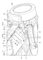
- FIG. 2 is a cross-sectional view taken along line AA in FIG.
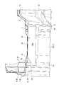
- FIG. 3 is a sectional view taken along line BB in FIG. 1.
- FIG. 6 is a partially cutaway perspective view showing a flow of traveling wind as viewed from obliquely below in FIG. 5. It is a perspective view which shows the other flow of the driving
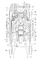
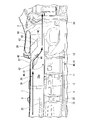
- the vehicle body floor includes a front floor 1 at the front of the vehicle body and a rear floor 2 at the rear of the vehicle body connected to the front floor 1.
- a floor tunnel portion 3 is formed to bulge upward in the vehicle width direction center portion of the front floor 1 along the longitudinal direction of the vehicle body.
- Side sills 4 and 4 which are vehicle body skeleton members are attached to both sides of the front floor 1.
- the side sill 4 has a closed cross-sectional structure composed of an inside sill 5 and a stiffener 6, and an outer panel 7 is joined to the outside thereof.
- the right side of the front floor 1 shows the inside sill 5
- the left side of the front floor 1 shows the outer panel 7 that constitutes the side wall of the vehicle body that covers the inside sill 5 and a stiffener 6 described later.
- a dashboard lower panel 19 (see FIG. 4) that rises upward is joined to the front end of the front floor 1, and a dashboard cross member 8 is joined to the back side of the connecting portion between the front floor 1 and the dashboard lower panel 19.
- tunnel frames 9 and 9 having a hat-shaped cross section that form a closed cross-section structure with the front floor 1 are joined along the longitudinal direction of the vehicle body.
- tunnel reinforcing members 10 and 11 are attached to the back side of the floor tunnel portion 3 in the front-rear direction so as to straddle the tunnel frames 9 and 9 along the vehicle width direction.
- a rear portion of the rear end portion of the front floor 1 is raised at the rear, and a middle cross member 12 that forms a closed cross-sectional structure is joined to the rear side of the joint portion in the vehicle width direction.
- rear frames 13 having a closed cross-sectional structure are disposed on the left and right along the longitudinal direction of the vehicle body.
- the rear frames 13, 13 are provided at positions higher than the side sills 4, 4 with an arrangement interval narrower than the arrangement intervals of the side sills 4, 4.
- the rear frame 13 is formed so as to incline outward as the front portion 13f moves toward the front side and incline downward.
- the rear portion 4r of the side sill 4 is joined to the front portion 13f of the rear frame 13.
- the fuel tank 14 is disposed below the front portion of the rear floor 2 disposed at a position higher than the front floor 1.
- Front side frames 15 are provided on the left and right sides of the vehicle body in the front-rear direction of the vehicle body, and front wheels FW and FW are disposed on both sides of the front side frames 15 and 15. Further, a sub frame 17 provided with a suspension part 16 for supporting the left and right rear wheels RW, RW is attached to the rear frame 13 from below. A spare tire pan 18 bulges downward on the rear part of the rear floor 2.
- a pair of vehicle body undercovers 20, 20 integrally formed of resin are distributed and attached to both sides of the floor tunnel portion 3 at the rear half of the lower surface of the vehicle body.
- the left and right vehicle body undercovers 20 and 20 are substantially symmetrical with each other, but have the same functional structure. Therefore, in the following description, the same portions are denoted by the same reference numerals.
- the outer end of the underbody cover 20 extends to the front of the flange portion 22 (see FIG. 4) of the lower wall 21 of the rear portion of the inside sill 5, and to the vicinity of the center portion in the width direction of the rear wheel RW. Has reached. Further, the inner end of the vehicle body undercover 20 extends to the outer edge of the lower wall 25 of the tunnel frames 9, 9.
- the vehicle body undercover 20 includes an undercover body 26 having a flat general surface 26 a that is continuous with the rear edge of the flat general surface 1 a of the front floor 1.
- an undercover body 26 having a flat general surface 26 a that is continuous with the rear edge of the flat general surface 1 a of the front floor 1.
- a concave front groove portion 27 and a rear groove portion 28 that extend obliquely toward the vehicle width direction center portion of the left and right rear wheels RW gradually toward the rear in the vehicle traveling direction. And are formed.
- the front groove portion 27 and the rear groove portion 28 are arranged in parallel to each other, and the rear ends of the front groove portion 27 and the rear groove portion 28 are connected to the general surface 26a through the inclined portions 42 and 43 so that the depth of the groove gradually decreases.
- the rear end edges of the front groove portion 27 and the rear groove portion 28 are connected to the general surface 26a by fold lines 44 and 45 extending in the front-rear direction, but the fold line 44 of the front groove portion 27 is processed obliquely so that the front side opens outward. ing.
- a concave portion (concave shape portion) 35 is provided at the front end of the front groove portion 27 of the undercover main body 26 and dropped from the front groove portion 27 at the outer end of the undercover main body 26. .
- a recessed portion (concave portion) 46 that is dropped from the rear groove portion 28 is provided in the front portion of the rear groove portion 28 of the undercover main body 26.
- These recessed portions 35 and 46 have a side wall facing the outer end of the undercover body 26, and allow air to flow in from the side.
- the front groove portions 27 and the rear groove portions 28 of the pair of left and right vehicle body undercovers 20 are directed rearward in the vehicle traveling direction and close to each other in the vehicle width direction center of the left and right rear wheels RW. Be placed.
- the recessed portion 35 and the recessed portion 46 are dropped because the side portion of the front floor 1 is inclined obliquely upward and joined to the inside sill 5 (see FIG. 4).
- the outer end of the under cover body 26 fixed by the lower wall 21 of the inside sill 5 also needs to correspond to the front floor 1 as will be described later. Therefore, for the same reason, the outer end of the front end portion of the undercover body 26 is dropped obliquely in alignment with the side portion of the front floor 1 being inclined obliquely upward.
- Behind the rear groove portion 28 of the under cover body 26 is a surface facing the road surface, at the front position of the rear wheel RW, the rear side along the rear end of the under cover body 26, and the outer side outside the under cover body 26.
- the inner side is bent slightly inward, and a recess 29 is formed along the rear groove 28 to be dropped from the general surface 26 a of the undercover body 26.
- the recess 29 includes a rear wall 30 formed along the outer peripheral surface of the rear wheel RW.
- the bottom wall 32 of the recess 29 is formed flat.
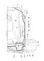
- the air flow that flows under the under cover body 26 flows rearward between the rear wheels RW and RW by the front groove portion 27 and the rear groove portion 28, but does not follow the front groove portion 27 and the rear groove portion 28, and moves backward.
- the air flow that has flowed into the flow recess 29 flows downward along the rear wall 30 and does not collide with the front surface of the rear wheel RW.
- a fixing hole 34 for fixing the rear outer end of the undercover body 26 to the lower wall 21 of the inside sill 5 with a bolt 33 is provided in the front portion of the bottom wall 32 of the recess 29 of the undercover body 26.
- the recessed portion 35 in the front portion of the front groove portion 27 of the undercover body 26 has a bottom wall 36, and the front outer end of the undercover body 26 is below the inside sill 5.
- a fixing hole 38 for fixing the wall 21 with a bolt 37 is provided.
- the recessed portion 35 and the recessed portion 29 are formed in a concave shape at the outer end of the under cover body 26, and the outer end of the under cover body 26 is fixed to the bottom wall 36 of the recessed portion 35.
- the bolts 37 inserted into the holes 38 and the bolts 33 inserted into the fixing holes 34 formed in the bottom wall 32 of the recess 29 are respectively fixed to the lower wall 21 of the inside sill 5.
- a fixing hole 41 for fixing the under cover body 26 to the lower wall 25 of the tunnel frame 9 with a bolt 40 is provided at the inner end of the under cover body 26 and at the center in the longitudinal direction of the vehicle body.
- a front cross member 47 is joined between the floor tunnel portion 3 and the side sill 4 of the front floor 1.
- the inside sill 5 having a hat-shaped cross-sectional structure opened to the outside in the vehicle width direction, and a vehicle having a closed cross-sectional structure joined to the upper and lower flange portions 22 of the inside sill 5.
- a stiffener 6 having a hat-shaped cross section that is open to the inside in the width direction, and an outer panel 7 that covers the stiffener 6 from the outside and forms a side wall of the vehicle body.
- the floor frame 48 which penetrates the front cross member 47 toward the vehicle body front-back direction is joined to the front floor 1 from side to side.
- the front floor 1 is bent in the middle on the outer side, joined to the bottom wall of the inside sill 5, and is formed so as to rise slightly upward at the position of the tunnel frame 9 on the front floor 1. Is made equal to the height of the general surface 1 a of the front floor 1. Therefore, the general surface 26a of the undercover body 26 attached across the lower wall 25 of the tunnel frame 9 and the lower wall 21 of the inside sill 5 can be formed flat by overlapping with the general surface 1a of the front floor 1. .
- a bulkhead 49 for closing the closed cross-section structure formed by the inside sill 5 and the stiffener 6 is attached.
- the general surface 26a of the undercover body 26 is curved along a curved surface 50 whose upper side is convex from the front to the rear of the vehicle body.
- the air flowing from the front floor 1 to the vehicle body undercover 20 when the vehicle is traveling can bring the general surface 1a of the front floor 1 and the general surface 26a of the undercover body 26 close to the road surface.
- the flow is rectified from the general surface 1a of the floor 1 to the general surface 26a of the undercover main body 26.
- the front groove 27 and the rear groove 28 are aligned.
- the air flows in a contracted state between the rear wheels RW and RW (see the arrow in FIG. 6), and the air resistance can be reduced without colliding with the rear wheels RW.
- the general surface 26a of the undercover body 26 is curved so as to follow the curved surface 50 whose upper side is convex, it is possible to create a portion where the depth from the road surface increases from the front to the rear.
- the wind effect can be improved, and the airflow can be rectified by bringing it closer to the road surface as the depth increases.
- the vehicle body under cover 20 is provided in the rear half of the lower surface of the vehicle body in front of the rear wheel RW, measures can be taken at a lower cost than when the vehicle body under cover 20 is provided over the entire lower surface of the front floor 1. .
- the portions other than the bottom wall 36 of the recessed portion 35 and the bottom wall 32 of the recessed portion 29 of the front groove portion 27 which is a fixing portion of the side sill 4 to the inside sill 5 are closer to the ground than the general surface 1a of the front floor 1. Therefore, the air flow velocity can be increased, and the effect of reducing the air resistance is enhanced.
- the attaching part with respect to the tunnel frame 9 of the inner side end of the undercover main body 26 is not restricted to one place.
- the recessed portion 46 of the rear groove portion 28 may also be fixed to the inside sill 5.
- the front groove portion 27, the rear groove portion 28, and the concave portion 29 may be formed separately from the undercover body 26.
- the case where the vehicle body undercover 20 is provided as a pair of left and right vehicle straddling the floor tunnel portion 3 is taken as an example, but the left and right vehicle body undercovers 20 and 20 may be integrally formed to cover the bottom of the floor tunnel portion 3.
- the vehicle body undercover according to the present invention is a vehicle body disposed in front of the rear wheel on the lower surface of the vehicle body and at least in the rear half portion of the vehicle body lower surface when viewed along the vehicle traveling direction.
- a vehicle body undercover capable of disposing the undercover body at a low position and solving the problem of road surface interference of the rectifying element.
- RW Rear wheel 20 Car body undercover 26 Undercover body 27 Front groove (groove) 28 Rear groove (groove) 29 Concave portion 30 Rear walls 35 and 46 Concave portion (concave portion) 1 Front floor (floor panel) 36 Bottom wall 32 Bottom wall 4 Side sill
Landscapes
- Engineering & Computer Science (AREA)
- Chemical & Material Sciences (AREA)
- Combustion & Propulsion (AREA)
- Transportation (AREA)
- Mechanical Engineering (AREA)
- Body Structure For Vehicles (AREA)
Abstract
Priority Applications (4)
| Application Number | Priority Date | Filing Date | Title |
|---|---|---|---|
| US13/997,418 US8814251B2 (en) | 2011-02-17 | 2011-12-14 | Under covers for vehicle body |
| CN201180067068.6A CN103370257B (zh) | 2011-02-17 | 2011-12-14 | 车身底罩 |
| JP2012557794A JP5461715B2 (ja) | 2011-02-17 | 2011-12-14 | 車体アンダカバー |
| MX2013006787A MX2013006787A (es) | 2011-02-17 | 2011-12-14 | Cubiertas inferiores para corroceria de vehiculo. |
Applications Claiming Priority (2)
| Application Number | Priority Date | Filing Date | Title |
|---|---|---|---|
| JP2011-032413 | 2011-02-17 | ||
| JP2011032413 | 2011-02-17 |
Publications (1)
| Publication Number | Publication Date |
|---|---|
| WO2012111228A1 true WO2012111228A1 (fr) | 2012-08-23 |
Family
ID=46672177
Family Applications (1)
| Application Number | Title | Priority Date | Filing Date |
|---|---|---|---|
| PCT/JP2011/078883 Ceased WO2012111228A1 (fr) | 2011-02-17 | 2011-12-14 | Caches inférieurs pour carrosserie de véhicule |
Country Status (5)
| Country | Link |
|---|---|
| US (1) | US8814251B2 (fr) |
| JP (1) | JP5461715B2 (fr) |
| CN (1) | CN103370257B (fr) |
| MX (1) | MX2013006787A (fr) |
| WO (1) | WO2012111228A1 (fr) |
Cited By (4)
| Publication number | Priority date | Publication date | Assignee | Title |
|---|---|---|---|---|
| JP2014125071A (ja) * | 2012-12-26 | 2014-07-07 | Daihatsu Motor Co Ltd | 自動車の下部車体構造 |
| JP2016052877A (ja) * | 2014-09-04 | 2016-04-14 | 本田技研工業株式会社 | 車体下部構造 |
| JP2019166985A (ja) * | 2018-03-23 | 2019-10-03 | マツダ株式会社 | 車体下面構造 |
| JP2022026371A (ja) * | 2020-07-31 | 2022-02-10 | 株式会社Subaru | 整流装置 |
Families Citing this family (14)
| Publication number | Priority date | Publication date | Assignee | Title |
|---|---|---|---|---|
| FR2997912B1 (fr) * | 2012-11-12 | 2016-04-01 | Renault Sas | Ecran aerodynamique inferieur de bouclier avant d'un vehicule automobile |
| US9932074B2 (en) * | 2015-08-31 | 2018-04-03 | Faraday & Future Inc. | Active vehicle skirt panel and the method of controlling the same |
| MX394710B (es) * | 2016-01-06 | 2025-03-24 | Nippon Steel Corp | Estructura de parte posterior de vehiculo. |
| JP6477632B2 (ja) * | 2016-08-22 | 2019-03-06 | マツダ株式会社 | 自動車の下部整流構造 |
| US10053163B1 (en) * | 2017-06-30 | 2018-08-21 | GM Global Technology Operations LLC | Vehicle aerodynamic underbody arrangement |
| US10442390B2 (en) * | 2017-08-25 | 2019-10-15 | Toyota Motor Engineering & Manufacturing North America, Inc. | Undercover assemblies including undercover reinforcement member |
| US10457341B2 (en) * | 2018-03-21 | 2019-10-29 | GM Global Technology Operations LLC | Underbody channel vortex generators |
| JP6893903B2 (ja) * | 2018-11-19 | 2021-06-23 | 小島プレス工業株式会社 | 車両用アンダーカバー |
| JP7139961B2 (ja) * | 2019-01-11 | 2022-09-21 | トヨタ自動車株式会社 | 車両用カバー部材 |
| FR3099742B1 (fr) * | 2019-08-06 | 2022-01-14 | Psa Automobiles Sa | Déflecteur à bords longitudinaux à extensions, pour un soubassement de véhicule |
| FR3114568B1 (fr) | 2020-09-29 | 2024-10-25 | Psa Automobiles Sa | Déflecteur à parois de retenue pour une structure d’un soubassement de véhicule |
| JP7765928B2 (ja) * | 2021-09-23 | 2025-11-07 | 株式会社Subaru | 車体の下面に方向性パターンのシボ加工面を有する車両、および、車両のアンダカバー部材 |
| JP2023061812A (ja) * | 2021-10-20 | 2023-05-02 | 本田技研工業株式会社 | 車体下部構造 |
| KR20240006907A (ko) * | 2022-07-07 | 2024-01-16 | 현대자동차주식회사 | 차량용 언더커버구조 |
Citations (5)
| Publication number | Priority date | Publication date | Assignee | Title |
|---|---|---|---|---|
| JPS608166A (ja) * | 1983-06-10 | 1985-01-17 | ドクトル・インジエニエ−ル・ハ−・ツエ−・エフ・ポルシエ・アクチエンゲゼルシヤフト | 自動車の下面のためのカバ−プレ−ト |
| JP2006062494A (ja) * | 2004-08-26 | 2006-03-09 | Mazda Motor Corp | 車両の床下構造 |
| JP2006298312A (ja) * | 2005-04-25 | 2006-11-02 | Mazda Motor Corp | 車体下部構造 |
| JP2007112340A (ja) * | 2005-10-21 | 2007-05-10 | Mazda Motor Corp | 自動車の下部構造 |
| JP2010264883A (ja) * | 2009-05-14 | 2010-11-25 | Honda Motor Co Ltd | 車体フロア下部構造 |
Family Cites Families (9)
| Publication number | Priority date | Publication date | Assignee | Title |
|---|---|---|---|---|
| DE3617538A1 (de) * | 1986-05-24 | 1987-11-26 | Porsche Ag | Kraftfahrzeug, insbesondere personenwagen |
| JPH01145678A (ja) | 1987-12-02 | 1989-06-07 | Fuji Xerox Co Ltd | 転写材の転写および剥離装置 |
| JPH088950Y2 (ja) * | 1988-03-15 | 1996-03-13 | ダイハツ工業株式会社 | エンジンアンダカバー |
| JP3164245B2 (ja) * | 1992-05-29 | 2001-05-08 | 日産自動車株式会社 | 自動車のアンダーフロア構造 |
| JPH1145678A (ja) | 1997-07-28 | 1999-02-16 | Hitachi Ltd | 走査像形成方法および走査像形成装置 |
| DE10130358A1 (de) * | 2001-06-23 | 2003-01-09 | Porsche Ag | Verkleidungsvorrichtung für die Unterseite eines Kraftfahrzeugs und Kraftfahrzeug |
| JP2008265677A (ja) | 2007-04-24 | 2008-11-06 | Mazda Motor Corp | 車体下部構造 |
| JP5067104B2 (ja) | 2007-10-03 | 2012-11-07 | トヨタ自動車株式会社 | 車両下部構造 |
| WO2011114509A1 (fr) * | 2010-03-19 | 2011-09-22 | トヨタ車体 株式会社 | Infrastructure de véhicule |
-
2011
- 2011-12-14 US US13/997,418 patent/US8814251B2/en active Active
- 2011-12-14 CN CN201180067068.6A patent/CN103370257B/zh active Active
- 2011-12-14 WO PCT/JP2011/078883 patent/WO2012111228A1/fr not_active Ceased
- 2011-12-14 JP JP2012557794A patent/JP5461715B2/ja not_active Expired - Fee Related
- 2011-12-14 MX MX2013006787A patent/MX2013006787A/es active IP Right Grant
Patent Citations (5)
| Publication number | Priority date | Publication date | Assignee | Title |
|---|---|---|---|---|
| JPS608166A (ja) * | 1983-06-10 | 1985-01-17 | ドクトル・インジエニエ−ル・ハ−・ツエ−・エフ・ポルシエ・アクチエンゲゼルシヤフト | 自動車の下面のためのカバ−プレ−ト |
| JP2006062494A (ja) * | 2004-08-26 | 2006-03-09 | Mazda Motor Corp | 車両の床下構造 |
| JP2006298312A (ja) * | 2005-04-25 | 2006-11-02 | Mazda Motor Corp | 車体下部構造 |
| JP2007112340A (ja) * | 2005-10-21 | 2007-05-10 | Mazda Motor Corp | 自動車の下部構造 |
| JP2010264883A (ja) * | 2009-05-14 | 2010-11-25 | Honda Motor Co Ltd | 車体フロア下部構造 |
Cited By (6)
| Publication number | Priority date | Publication date | Assignee | Title |
|---|---|---|---|---|
| JP2014125071A (ja) * | 2012-12-26 | 2014-07-07 | Daihatsu Motor Co Ltd | 自動車の下部車体構造 |
| JP2016052877A (ja) * | 2014-09-04 | 2016-04-14 | 本田技研工業株式会社 | 車体下部構造 |
| JP2019166985A (ja) * | 2018-03-23 | 2019-10-03 | マツダ株式会社 | 車体下面構造 |
| JP7028009B2 (ja) | 2018-03-23 | 2022-03-02 | マツダ株式会社 | 車体下面構造 |
| JP2022026371A (ja) * | 2020-07-31 | 2022-02-10 | 株式会社Subaru | 整流装置 |
| JP7549481B2 (ja) | 2020-07-31 | 2024-09-11 | 株式会社Subaru | 整流装置 |
Also Published As
| Publication number | Publication date |
|---|---|
| JPWO2012111228A1 (ja) | 2014-07-03 |
| MX2013006787A (es) | 2013-11-04 |
| JP5461715B2 (ja) | 2014-04-02 |
| CN103370257A (zh) | 2013-10-23 |
| CN103370257B (zh) | 2015-11-25 |
| US20130278011A1 (en) | 2013-10-24 |
| US8814251B2 (en) | 2014-08-26 |
Similar Documents
| Publication | Publication Date | Title |
|---|---|---|
| JP5461715B2 (ja) | 車体アンダカバー | |
| JP6164249B2 (ja) | 自動車の前部床下整流構造 | |
| CN103619695B (zh) | 车辆前部的下部车体结构 | |
| JP5768930B2 (ja) | エアガイド構造 | |
| JP6172202B2 (ja) | 自動車の床下構造 | |
| CN110294031B (zh) | 车身下表面结构 | |
| WO2013122050A1 (fr) | Structure pour partie inférieure de caisse de véhicule de véhicule | |
| JP2009029334A (ja) | 車体下部構造 | |
| CN105722747B (zh) | 车身侧部构造 | |
| JP7234515B2 (ja) | 車体前部構造 | |
| JP5522539B2 (ja) | 車両の下部車体構造 | |
| JP6200518B2 (ja) | 車体側部構造 | |
| JP6123742B2 (ja) | 車両の下部構造 | |
| WO2019203116A1 (fr) | Structure pour partie inférieure de carrosserie de véhicule | |
| JP6237669B2 (ja) | 車両の上部車体構造 | |
| JP5842892B2 (ja) | 車両床下構造 | |
| JP5996420B2 (ja) | 自動車の下部車体構造 | |
| JP6237670B2 (ja) | 車両の上部車体構造 | |
| JP7087526B2 (ja) | 車体下面構造 | |
| JP7087527B2 (ja) | 車体下面構造 | |
| JP5496727B2 (ja) | 自動車の前部車体構造 | |
| JP7451933B2 (ja) | 車両の下部構造 | |
| CN114750830B (zh) | 车架结构 | |
| JP6304325B2 (ja) | 自動車の整流構造 | |
| JP6076774B2 (ja) | 自動車の前部車体構造 |
Legal Events
| Date | Code | Title | Description |
|---|---|---|---|
| 121 | Ep: the epo has been informed by wipo that ep was designated in this application |
Ref document number: 11858508 Country of ref document: EP Kind code of ref document: A1 |
|
| ENP | Entry into the national phase |
Ref document number: 2012557794 Country of ref document: JP Kind code of ref document: A |
|
| WWE | Wipo information: entry into national phase |
Ref document number: MX/A/2013/006787 Country of ref document: MX |
|
| WWE | Wipo information: entry into national phase |
Ref document number: 13997418 Country of ref document: US |
|
| WWE | Wipo information: entry into national phase |
Ref document number: 1301004390 Country of ref document: TH |
|
| NENP | Non-entry into the national phase |
Ref country code: DE |
|
| 122 | Ep: pct application non-entry in european phase |
Ref document number: 11858508 Country of ref document: EP Kind code of ref document: A1 |