WO2012111264A1 - Soupape de commande - Google Patents
Soupape de commande Download PDFInfo
- Publication number
- WO2012111264A1 WO2012111264A1 PCT/JP2012/000592 JP2012000592W WO2012111264A1 WO 2012111264 A1 WO2012111264 A1 WO 2012111264A1 JP 2012000592 W JP2012000592 W JP 2012000592W WO 2012111264 A1 WO2012111264 A1 WO 2012111264A1
- Authority
- WO
- WIPO (PCT)
- Prior art keywords
- valve
- rotor
- hole
- internal passage
- guide
- Prior art date
- Legal status (The legal status is an assumption and is not a legal conclusion. Google has not performed a legal analysis and makes no representation as to the accuracy of the status listed.)
- Ceased
Links
Images

Classifications
-
- F—MECHANICAL ENGINEERING; LIGHTING; HEATING; WEAPONS; BLASTING
- F16—ENGINEERING ELEMENTS AND UNITS; GENERAL MEASURES FOR PRODUCING AND MAINTAINING EFFECTIVE FUNCTIONING OF MACHINES OR INSTALLATIONS; THERMAL INSULATION IN GENERAL
- F16K—VALVES; TAPS; COCKS; ACTUATING-FLOATS; DEVICES FOR VENTING OR AERATING
- F16K31/00—Actuating devices; Operating means; Releasing devices
- F16K31/02—Actuating devices; Operating means; Releasing devices electric; magnetic
- F16K31/04—Actuating devices; Operating means; Releasing devices electric; magnetic using a motor
-
- F—MECHANICAL ENGINEERING; LIGHTING; HEATING; WEAPONS; BLASTING
- F16—ENGINEERING ELEMENTS AND UNITS; GENERAL MEASURES FOR PRODUCING AND MAINTAINING EFFECTIVE FUNCTIONING OF MACHINES OR INSTALLATIONS; THERMAL INSULATION IN GENERAL
- F16K—VALVES; TAPS; COCKS; ACTUATING-FLOATS; DEVICES FOR VENTING OR AERATING
- F16K39/00—Devices for relieving the pressure on the sealing faces
- F16K39/02—Devices for relieving the pressure on the sealing faces for lift valves
-
- B—PERFORMING OPERATIONS; TRANSPORTING
- B60—VEHICLES IN GENERAL
- B60H—ARRANGEMENTS OF HEATING, COOLING, VENTILATING OR OTHER AIR-TREATING DEVICES SPECIALLY ADAPTED FOR PASSENGER OR GOODS SPACES OF VEHICLES
- B60H1/00—Heating, cooling or ventilating devices
- B60H1/00485—Valves for air-conditioning devices, e.g. thermostatic valves
-
- F—MECHANICAL ENGINEERING; LIGHTING; HEATING; WEAPONS; BLASTING
- F16—ENGINEERING ELEMENTS AND UNITS; GENERAL MEASURES FOR PRODUCING AND MAINTAINING EFFECTIVE FUNCTIONING OF MACHINES OR INSTALLATIONS; THERMAL INSULATION IN GENERAL
- F16K—VALVES; TAPS; COCKS; ACTUATING-FLOATS; DEVICES FOR VENTING OR AERATING
- F16K1/00—Lift valves or globe valves, i.e. cut-off apparatus with closure members having at least a component of their opening and closing motion perpendicular to the closing faces
-
- F—MECHANICAL ENGINEERING; LIGHTING; HEATING; WEAPONS; BLASTING
- F16—ENGINEERING ELEMENTS AND UNITS; GENERAL MEASURES FOR PRODUCING AND MAINTAINING EFFECTIVE FUNCTIONING OF MACHINES OR INSTALLATIONS; THERMAL INSULATION IN GENERAL
- F16K—VALVES; TAPS; COCKS; ACTUATING-FLOATS; DEVICES FOR VENTING OR AERATING
- F16K11/00—Multiple-way valves, e.g. mixing valves; Pipe fittings incorporating such valves
- F16K11/10—Multiple-way valves, e.g. mixing valves; Pipe fittings incorporating such valves with two or more closure members not moving as a unit
- F16K11/14—Multiple-way valves, e.g. mixing valves; Pipe fittings incorporating such valves with two or more closure members not moving as a unit operated by one actuating member, e.g. a handle
- F16K11/18—Multiple-way valves, e.g. mixing valves; Pipe fittings incorporating such valves with two or more closure members not moving as a unit operated by one actuating member, e.g. a handle with separate operating movements for separate closure members
-
- F—MECHANICAL ENGINEERING; LIGHTING; HEATING; WEAPONS; BLASTING
- F16—ENGINEERING ELEMENTS AND UNITS; GENERAL MEASURES FOR PRODUCING AND MAINTAINING EFFECTIVE FUNCTIONING OF MACHINES OR INSTALLATIONS; THERMAL INSULATION IN GENERAL
- F16K—VALVES; TAPS; COCKS; ACTUATING-FLOATS; DEVICES FOR VENTING OR AERATING
- F16K31/00—Actuating devices; Operating means; Releasing devices
- F16K31/44—Mechanical actuating means
- F16K31/50—Mechanical actuating means with screw-spindle or internally threaded actuating means
- F16K31/508—Mechanical actuating means with screw-spindle or internally threaded actuating means the actuating element being rotatable, non-rising, and driving a non-rotatable axially-sliding element
-
- F—MECHANICAL ENGINEERING; LIGHTING; HEATING; WEAPONS; BLASTING
- F16—ENGINEERING ELEMENTS AND UNITS; GENERAL MEASURES FOR PRODUCING AND MAINTAINING EFFECTIVE FUNCTIONING OF MACHINES OR INSTALLATIONS; THERMAL INSULATION IN GENERAL
- F16K—VALVES; TAPS; COCKS; ACTUATING-FLOATS; DEVICES FOR VENTING OR AERATING
- F16K39/00—Devices for relieving the pressure on the sealing faces
- F16K39/02—Devices for relieving the pressure on the sealing faces for lift valves
- F16K39/022—Devices for relieving the pressure on the sealing faces for lift valves using balancing surfaces
Definitions
- the present invention relates to a control valve that controls the flow of a working fluid, and more particularly to a control valve that includes an actuator for electrically adjusting the valve opening.
- An automobile air conditioner is generally configured by arranging a compressor, a condenser, an evaporator, and the like in a refrigerant circulation passage.
- Various control valves are provided for switching the refrigerant circulation passage and adjusting the refrigerant flow rate according to the operating state of the refrigeration cycle (see, for example, Patent Document 1).
- a control valve there is a mechanical valve whose valve part is opened and closed by a balance between the force due to the pressure received from the refrigerant and the biasing force of the spring against it, and an actuator for electrically adjusting the opening degree from the outside.
- the electrically driven valve provided is used as appropriate.
- an electrically driven valve when an electrically driven valve is provided in such an air conditioner, a motor, a solenoid, or the like is used as the actuator, but it is desirable that the actuator can be configured compactly for space saving and power saving.
- an electrically driven valve having a large-diameter valve portion that requires a particularly large opening / closing driving force is provided with a back pressure canceling structure for canceling the fluid pressure acting on the valve body.
- a configuration in which a seal member is provided on a sliding surface of a valve body that defines a back pressure chamber is widely used in order to maintain the back pressure.
- the valve body in order to maintain the stability of the valve portion when the electrically driven valve is not energized, the valve body is usually provided with a spring that generates an urging force for maintaining the valve open or closed state. For this reason, in order to drive the valve body, a driving force that overcomes the urging force of the spring is also required. Therefore, in order to make the actuator small, it is necessary to reduce the influence of sliding force and urging force acting on the valve body.
- the present invention has been made in view of such a problem, and one of its purposes is to make the actuator compactly configurable by suppressing the opening / closing driving force of the electrically driven valve to be small.
- a valve drive body integrally including a provided guide hole, a valve body that opens and closes the valve portion by contacting and separating from the valve hole, a guide portion that is slidably supported by the guide hole, and a fluid that acts on the valve body
- a canceling structure for canceling the influence of pressure a seal member provided on the sliding surface of the guide part, an actuator provided at one end of the body, and the actuator driven in the axial direction by the actuator,
- the opening / closing driving force of the electrically driven valve can be kept small, and the actuator can be configured compactly.
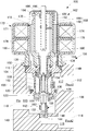
- FIG. 1 to 3 are sectional views showing the configuration and operation of the control valve according to the first embodiment.
- the control valve of this embodiment assumes application to the heat pump type
- control valve 100 is configured as an electric valve driven by a stepping motor, and is configured by assembling a valve main body 101 and a motor unit 102.
- the valve body 101 is configured by coaxially housing a large-diameter first valve 105 and a small-diameter second valve 106 in a bottomed cylindrical body 104.
- a large-diameter valve body 130, a small-diameter valve body 132, and a valve operating body 134 are arranged coaxially (on the same axis).
- the flow rate of the refrigerant flowing through the first internal passage is adjusted by adjusting the opening degree of the first valve 105 by the valve body 130 contacting and separating from the valve hole 120 from the upstream side.
- a valve member 136 made of a ring-shaped elastic body (for example, rubber) is fitted on the outer peripheral surface of the valve body 130, and the valve member 136 is seated on the valve seat 122, so that the first valve 105 is completely It becomes possible to close.
- a small cylindrical guide member 140 is disposed in the lower half of the body 104.
- the guide member 140 is provided coaxially with the valve body 130 at the center of the second internal passage, and the lower half thereof is press-fitted into the body 104.
- the guide member 140 has a guide hole 142 formed on the inner peripheral surface of the upper half thereof, and a valve hole 144 formed on the lower end thereof. Further, a valve seat 146 is formed by the upper end opening edge of the valve hole 144.
- a communication hole that communicates the inside and the outside is provided on the surface of the guide member 140 facing the introduction port 110.
- a common high-pressure chamber 115 communicating with the introduction port 110 is formed upstream of the valve hole 120 and the valve hole 144, and a low-pressure chamber 117 communicating with the first outlet port 112 is formed downstream of the valve hole 120.
- a low pressure chamber 119 communicating with the second outlet port 114 is formed on the downstream side of the valve hole 144.
- the valve body 130 is continuously provided with a guide portion 148 through a reduced diameter portion. That is, the valve body 130 and the guide portion 148 constitute a stepped cylindrical “valve drive body” in which the diameter is reduced.
- the guide part 148 is disposed in the low pressure chamber 117.
- the upper end portion of the guide portion 148 is slidably supported in the guide hole 118 via the O-ring 149 (functioning as a “seal member”), so that the valve body 130 can be stably operated in the opening / closing direction. It is secured.
- a back pressure chamber 150 is formed between the guide portion 148 and the partition member 116.
- a communication passage 151 that penetrates the valve body 130 and the guide portion 148 is formed, and the high pressure chamber 115 and the back pressure chamber 150 are communicated with each other. Thereby, the upstream pressure Pin introduced from the introduction port 110 is always filled in the back pressure chamber 150.
- the effective diameter A of the valve hole 120 and the effective diameter B of the guide hole 118 are set equal (the effective pressure receiving area of the valve body 130 and the effective pressure receiving area of the guide portion 148 are substantially equal).
- the influence of the refrigerant pressure acting on the valve body 130 is canceled.
- the sealing performance of the sliding portion of the guide portion 148 is secured, and dust or the like is prevented from being caught in the sliding portion.
- a long transmission rod 152 (functioning as a “transmission member”) is coaxially inserted inside the valve body 130, and a valve body 132 is disposed at the lower end portion of the transmission rod 152 so as to be operatively connected. ing.
- the upper end portion of the transmission rod 152 penetrates the bottom portion of the valve operating body 134, and the distal end portion thereof is caulked outward to form a locking portion 154. That is, the upper end of the transmission rod 152 is supported on the bottom of the valve operating body 134.
- a lower end portion of the transmission rod 152 is a locking portion 156 that protrudes outward in the radial direction.
- a spring receiving portion 158 that protrudes outward in the radial direction is provided at the center of the transmission rod 152.
- a spring 160 (functioning as an “urging member”) is interposed between the inner wall of the guide portion 148 and the spring receiving portion 158. That is, the valve body 130 and the transmission rod 152 can be relatively displaced in the axial direction, but the locking portion 154 is normally urged in the axial direction by the spring 160 to maintain the stretched state as illustrated. .
- the valve body 132 has a stepped columnar shape and is coaxially disposed below the valve body 130.
- the valve body 132 is slidably inserted into the guide member 140, and a tip portion thereof is disposed to face the valve hole 144.
- the valve body 132 is configured as a so-called needle valve body, and a sharp tip portion thereof is inserted into and extracted from the valve hole 144. Then, the second valve 106 is opened and closed by the valve body 132 being attached to and detached from the valve seat 146.
- the upper half part of the valve body 132 is a cylindrical accommodating part, and the engaging part 156 of the transmission rod 152 is accommodated so as to be capable of relative displacement in the axial direction.
- the upper end opening of the valve body 132 is a locking portion 162 that is slightly crimped inward, thereby preventing the locking portion 156 from coming off.
- a spring 164 (which functions as a “second biasing member”) that biases the valve body 132 in the valve closing direction is interposed between the valve body 130 and the valve body 132.
- the valve body 132 and the transmission rod 152 can be displaced relative to each other in the axial direction by the length of the accommodating portion, but normally the direction in which the locking portion 162 and the locking portion 156 are engaged by the spring 164.
- the load of the spring 164 is set to be considerably smaller than the load of the spring 160.
- the load of the spring 160 in the illustrated state is set to be about 600 g and the load of the spring 164 is about 100 g.
- the resultant force of the load of the spring 160 and the load of the spring 164 is set to be larger than the sliding resistance (sliding force of the valve drive body: for example, 600 g weight) of the O-ring 149 of the guide portion 148.
- the load of the spring 160 may be set to 700 g, for example, so as to be set larger than the sliding force of the valve driving body.
- the valve operating body 134 has a stepped cylindrical shape, and a male thread portion is formed on the outer peripheral portion thereof.
- the male screw portion is screwed into the female screw portion of the bearing portion 126.
- a plurality (four in this embodiment) of leg portions 153 extending outward in the radial direction are provided at the upper end portion of the valve operating body 134 and are fitted to the rotor of the motor unit 102.
- the valve actuator 134 receives the rotational driving force of the motor unit 102 and rotates, and converts the rotational force into a translational force.
- valve operating body 134 when the valve operating body 134 rotates, the valve operating body 134 is displaced in the axial direction by a screw mechanism (functioning as an “operation converting mechanism”), and drives the valve body 130 or the valve body 132 in the opening / closing direction.
- a screw mechanism functioning as an “operation converting mechanism”
- the valve body 130 and the valve operating body 134 When the first valve 105 is opened, the valve body 130 and the valve operating body 134 operate integrally, and when the second valve 106 is opened, the valve body 132 and the valve operating body 134 operate integrally.
- the rotor 172 includes a rotating shaft 174 formed in a cylindrical shape and a magnet 176 disposed on the outer periphery of the rotating shaft 174.
- the magnet 176 is magnetized to 24 poles.
- An internal space that extends over substantially the entire length of the motor unit 102 is formed inside the rotating shaft 174.
- a guide portion 178 extending parallel to the axis is provided at a specific location on the inner peripheral surface of the rotation shaft 174.
- the guide part 178 forms a protrusion for engaging with a rotation stopper, which will be described later, and is constituted by a single protrusion that extends parallel to the axis.
- the lower end portion of the rotating shaft 174 is slightly reduced in diameter, and four guide portions 180 extending in parallel to the axis are provided on the inner peripheral surface thereof.
- the guide portion 180 is constituted by a pair of protrusions extending in parallel to the axis, and is provided on the inner peripheral surface of the rotating shaft 174 every 90 degrees.
- the four guide portions 180 are fitted with the four leg portions 153 of the valve operating body 134 described above so that the rotor 172 and the valve operating body 134 can rotate together.
- the valve actuating member 134 is allowed to be displaced in the axial direction along the guide portion 180 although the relative displacement in the rotational direction with respect to the rotor 172 is restricted. That is, the valve operating body 134 is driven in the opening / closing direction of the valve body 132 while rotating together with the rotor 172.
- a long shaft 182 is disposed inside the rotor 172 along the axis thereof.
- the upper end of the shaft 182 is fixed in a cantilever manner by being press-fitted into the center of the bottom of the sleeve 170, and extends into the internal space in parallel with the guide portion 178.
- the shaft 182 is disposed on the same axis as the valve operating body 134.
- the shaft 182 is provided with a spiral guide portion 184 that extends over substantially the entire length thereof.
- the guide part 184 is made of a coil-shaped member and is fitted on the outer surface of the shaft 182. An upper end portion of the guide portion 184 is folded back to form a locking portion 186.
- a helical rotation stopper 188 is rotatably engaged with the guide portion 184.
- the rotation stopper 188 includes a helical engagement portion 190 that engages with the guide portion 184 and a power transmission portion 192 that is supported by the rotation shaft 174.
- the engaging portion 190 has a shape of a one-turn coil, and a power transmission portion 192 that extends outward in the radial direction is continuously provided at a lower end portion of the engaging portion 190.
- the distal end portion of the power transmission unit 192 is engaged with the guide unit 178. That is, the power transmission part 192 is brought into contact with and locked on one protrusion of the guide part 178. For this reason, the rotation stopper 188 is restricted in relative rotation in the rotation direction by the rotation shaft 174, but is allowed to move in the axial direction while sliding on the guide portion 178.
- the rotation stopper 188 rotates integrally with the rotor 172 and is driven in the axial direction by the engagement portion 190 being guided along the guide portion 184.
- the driving range of the rotation stopper 188 in the axial direction is restricted by the engaging portions formed at both ends of the guide portion 178.
- This figure shows a state in which the rotation stopper 188 is in the intermediate position.
- the rotation stopper 188 is displaced upward and locked to the locking portion 186, the position becomes the top dead center.
- the rotation stopper 188 is displaced downward, it is locked at its bottom dead center.
- the rotor 172 has an upper end portion rotatably supported by the shaft 182 and a lower end portion rotatably supported by the bearing portion 126.
- a bottomed cylindrical end member 194 is provided so as to seal the upper end opening of the rotating shaft 174, and a portion of the cylindrical shaft 196 provided in the center of the end member 194 is a shaft 182. It is supported by. That is, the bearing portion 126 is a bearing portion on one end side, and the sliding portion of the shaft 182 with the cylindrical shaft 196 is a bearing portion on the other end side.
- the control valve 100 configured as described above functions as a stepping motor drive type control valve whose valve opening can be adjusted by drive control of the motor unit 102.
- a control unit (not shown) of the vehicle air conditioning apparatus calculates the number of driving steps of the stepping motor according to the set opening and supplies a driving current (driving pulse) to the exciting coil 171.
- the rotor 172 rotates, and on the one hand, the valve operating body 134 is driven to rotate to adjust the opening degree of the large-diameter first valve 105 and small-diameter second valve 106 to the set opening degree, and on the other hand, the rotation stopper 188. Is driven along the guide portion 184, so that the operating range of each valve element is regulated.
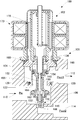
- the valve operating body that rotates together with the rotor 172 as shown in FIG. 2 when the rotor 172 is driven to rotate in one direction (forward rotation) from the state of FIG. 134 is lowered by the screw mechanism.
- the valve body 130 is displaced in the valve opening direction so as to be pushed down while the valve operating body 134 is in contact with the guide portion 148.
- the valve body 130 is driven in a range between the fully closed state shown in FIG. 1 and the fully opened position shown in FIG. 2, and the opening degree of the first valve 105 is adjusted.
- the driving force of the motor unit 102 is large enough to overcome the resultant force of the sliding force (sliding resistance) of the O-ring 149 and the urging force (reaction force) of the spring 164.
- the motor unit 102 only needs to generate a driving force that can overcome the resultant force of the biasing force (for example, the maximum weight of 200 g) of the spring 164 having a small load and the sliding force (for example, 600 g) of the O-ring 149.
- the engagement state of the locking portion 162 of the valve body 132 and the locking portion 156 of the transmission rod 152 is released, an excessive pressing force may be applied between the valve body 132 and the valve seat 146. Absent.
- the driving force of the motor unit 102 is large enough to overcome the difference (400 to 500 g weight) between the sliding force of the O-ring 149 (for example, 600 g weight) and the urging force of the spring 164 (100 to 200 g weight). If there is enough.
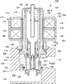
- the rotor 172 when executing the small diameter control, the rotor 172 is rotationally driven (reversely rotated) in the other direction from the state of FIG. 1 to displace the valve element 132 in the valve opening direction, and the second valve as shown in FIG. 106 opens. That is, the valve operating body 134 that rotates together with the rotor 172 is raised by the screw mechanism, and the transmission rod 152 and the valve body 132 are displaced in the valve opening direction so as to lift the locking portion 154. The valve body 132 is driven in a range between the fully closed state shown in FIG. 1 and the fully opened position shown in FIG. 3, and the opening degree of the second valve 106 is adjusted. At this time, the driving force of the motor unit 102 only needs to be large enough to overcome the resultant force of the urging force (reaction force) of the spring 160 and the urging force (reaction force) of the spring 164.
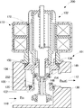
- the control valve 200 is configured as an electric valve driven by a stepping motor, and is configured by assembling a valve body 201 and a motor unit 102.
- the body 204 is provided with an introduction port 110 and a lead-out port 112, and a valve hole 120 is provided in an internal passage connecting them.
- a spring receiving portion 158 is provided at the lower end portion of the transmission rod 252.
- the load of the spring 160 in the illustrated state (for example, 700 g weight) is set to be larger than the sliding resistance in the O-ring 149 (sliding force of the valve drive body: for example, 600 g weight). .
- valve operating body 134 and the transmission rod 152 are configured separately so as to be able to be connected and disconnected.
- the valve operating body 134 and the transmission rod 152 may be integrally configured so as not to be relatively displaced. That is, you may comprise as an operation
- control valve is applied to a cooling / heating device for an electric vehicle.
- the control valve may be applied to a vehicle equipped with an internal combustion engine or a hybrid vehicle equipped with an internal combustion engine and an electric motor.
- coolant as a working fluid was shown, it can also be comprised as an electric drive valve which controls the flow of working fluids other than a refrigerant
- the example in which the stepping motor is used as the actuator of the control valve is shown, but other types of motors or solenoids may be used as the actuator.
- control valve 101 valve body, 102 motor unit, 104 body, 105 first valve, 106 second valve, 110 introduction port, 112 first derivation port, 114 second derivation port, 118 guide hole, 120 valve hole, 122 Valve seat, 130, 132 valve body, 134 valve actuator, 144 valve hole, 146 valve seat, 148 guide section, 149 O-ring, 150 back pressure chamber, 152 transmission rod, 160, 164 spring, 172 rotor, 173 stator, 182 shaft, 184 guide part, 186 locking part, 188 rotation stopper, 190 engaging part, 192 power transmission part, 200 control valve, 201 valve body, 204 body, 252 transmission rod.
Landscapes
- Engineering & Computer Science (AREA)
- General Engineering & Computer Science (AREA)
- Mechanical Engineering (AREA)
- Physics & Mathematics (AREA)
- Thermal Sciences (AREA)
- Electrically Driven Valve-Operating Means (AREA)
- Lift Valve (AREA)
- Multiple-Way Valves (AREA)
Abstract
Priority Applications (2)
| Application Number | Priority Date | Filing Date | Title |
|---|---|---|---|
| EP12747421.1A EP2677218A4 (fr) | 2011-02-18 | 2012-01-31 | Soupape de commande |
| KR1020137024385A KR20140008390A (ko) | 2011-02-18 | 2012-01-31 | 제어 밸브 |
Applications Claiming Priority (2)
| Application Number | Priority Date | Filing Date | Title |
|---|---|---|---|
| JP2011-032864 | 2011-02-18 | ||
| JP2011032864A JP5699266B2 (ja) | 2011-02-18 | 2011-02-18 | 制御弁 |
Publications (1)
| Publication Number | Publication Date |
|---|---|
| WO2012111264A1 true WO2012111264A1 (fr) | 2012-08-23 |
Family
ID=46672211
Family Applications (1)
| Application Number | Title | Priority Date | Filing Date |
|---|---|---|---|
| PCT/JP2012/000592 Ceased WO2012111264A1 (fr) | 2011-02-18 | 2012-01-31 | Soupape de commande |
Country Status (4)
| Country | Link |
|---|---|
| EP (1) | EP2677218A4 (fr) |
| JP (1) | JP5699266B2 (fr) |
| KR (1) | KR20140008390A (fr) |
| WO (1) | WO2012111264A1 (fr) |
Cited By (2)
| Publication number | Priority date | Publication date | Assignee | Title |
|---|---|---|---|---|
| CN111561571A (zh) * | 2019-02-14 | 2020-08-21 | 株式会社Tgk | 电动阀 |
| CN111902664A (zh) * | 2018-09-11 | 2020-11-06 | 穆格日本有限公司 | 阀开闭用电动致动器及阀开闭用电动致动器的驱动方法 |
Families Citing this family (3)
| Publication number | Priority date | Publication date | Assignee | Title |
|---|---|---|---|---|
| JP7127838B2 (ja) * | 2019-02-19 | 2022-08-30 | タイム技研株式会社 | 流量制御弁 |
| CN212079907U (zh) * | 2020-03-30 | 2020-12-04 | 盾安环境技术有限公司 | 螺母组件以及电子膨胀阀 |
| CN120187991A (zh) * | 2022-11-21 | 2025-06-20 | 丹佛斯有限公司 | 用于热泵阀组件的致动器、用于热泵的阀组件以及具有阀组件的热泵 |
Citations (3)
| Publication number | Priority date | Publication date | Assignee | Title |
|---|---|---|---|---|
| JPS60127173U (ja) * | 1984-01-31 | 1985-08-27 | エスエムシ−株式会社 | 水撃防止形2ポ−ト弁 |
| JPH0227072U (fr) * | 1988-08-09 | 1990-02-22 | ||
| JPH08512124A (ja) * | 1994-04-29 | 1996-12-17 | エッチアール テキストロン インコーポレイテッド | 圧力均衡ソレノイドバルブ |
Family Cites Families (4)
| Publication number | Priority date | Publication date | Assignee | Title |
|---|---|---|---|---|
| JPS576856U (fr) * | 1980-06-13 | 1982-01-13 | ||
| JPS61218354A (ja) * | 1985-03-07 | 1986-09-27 | Saginomiya Seisakusho Inc | ステツピングモ−タ−バルブ |
| JPS6412181A (en) * | 1987-07-03 | 1989-01-17 | Matsushita Electric Industrial Co Ltd | Motor-driven three-way valve |
| JP4283069B2 (ja) * | 2003-04-24 | 2009-06-24 | 株式会社不二工機 | 複合弁 |
-
2011
- 2011-02-18 JP JP2011032864A patent/JP5699266B2/ja not_active Expired - Fee Related
-
2012
- 2012-01-31 WO PCT/JP2012/000592 patent/WO2012111264A1/fr not_active Ceased
- 2012-01-31 EP EP12747421.1A patent/EP2677218A4/fr not_active Withdrawn
- 2012-01-31 KR KR1020137024385A patent/KR20140008390A/ko not_active Withdrawn
Patent Citations (3)
| Publication number | Priority date | Publication date | Assignee | Title |
|---|---|---|---|---|
| JPS60127173U (ja) * | 1984-01-31 | 1985-08-27 | エスエムシ−株式会社 | 水撃防止形2ポ−ト弁 |
| JPH0227072U (fr) * | 1988-08-09 | 1990-02-22 | ||
| JPH08512124A (ja) * | 1994-04-29 | 1996-12-17 | エッチアール テキストロン インコーポレイテッド | 圧力均衡ソレノイドバルブ |
Non-Patent Citations (1)
| Title |
|---|
| See also references of EP2677218A4 * |
Cited By (4)
| Publication number | Priority date | Publication date | Assignee | Title |
|---|---|---|---|---|
| CN111902664A (zh) * | 2018-09-11 | 2020-11-06 | 穆格日本有限公司 | 阀开闭用电动致动器及阀开闭用电动致动器的驱动方法 |
| CN111902664B (zh) * | 2018-09-11 | 2023-06-09 | 穆格日本有限公司 | 阀开闭用电动致动器及阀开闭用电动致动器的驱动方法 |
| CN111561571A (zh) * | 2019-02-14 | 2020-08-21 | 株式会社Tgk | 电动阀 |
| CN111561571B (zh) * | 2019-02-14 | 2023-11-21 | 株式会社Tgk | 电动阀 |
Also Published As
| Publication number | Publication date |
|---|---|
| KR20140008390A (ko) | 2014-01-21 |
| JP5699266B2 (ja) | 2015-04-08 |
| EP2677218A4 (fr) | 2016-07-13 |
| JP2012172702A (ja) | 2012-09-10 |
| EP2677218A1 (fr) | 2013-12-25 |
Similar Documents
| Publication | Publication Date | Title |
|---|---|---|
| JP5740586B2 (ja) | ステッピングモータ駆動式の制御弁 | |
| JP5572809B2 (ja) | 制御弁 | |
| JP5842185B2 (ja) | 制御弁 | |
| JP5740596B2 (ja) | 制御弁 | |
| JP5699266B2 (ja) | 制御弁 | |
| EP2685143B1 (fr) | Vanne de regulation | |
| WO2012108140A1 (fr) | Vanne de commande | |
| JP5771800B2 (ja) | 制御弁 | |
| JP5866600B2 (ja) | 車両用冷暖房装置、複合弁および制御弁 | |
| JP2012237343A (ja) | ステッピングモータ駆動式の制御弁 | |
| JP4570484B2 (ja) | 複合弁およびヒートポンプ式空気調和装置およびその制御方法 | |
| WO2012090362A1 (fr) | Système de chauffage, ventilation et conditionnement d'air pour véhicule | |
| JP5760203B2 (ja) | 車両用冷暖房装置 | |
| JP2024114419A (ja) | 複合弁および複合弁制御装置 | |
| JP2025130738A (ja) | 電動弁 | |
| JP5699263B2 (ja) | 車両用冷暖房装置に用いられる制御弁 |
Legal Events
| Date | Code | Title | Description |
|---|---|---|---|
| 121 | Ep: the epo has been informed by wipo that ep was designated in this application |
Ref document number: 12747421 Country of ref document: EP Kind code of ref document: A1 |
|
| NENP | Non-entry into the national phase |
Ref country code: DE |
|
| REEP | Request for entry into the european phase |
Ref document number: 2012747421 Country of ref document: EP |
|
| WWE | Wipo information: entry into national phase |
Ref document number: 2012747421 Country of ref document: EP |
|
| ENP | Entry into the national phase |
Ref document number: 20137024385 Country of ref document: KR Kind code of ref document: A |