WO2012111382A1 - Appareil de façonnage en trois dimensions - Google Patents
Appareil de façonnage en trois dimensions Download PDFInfo
- Publication number
- WO2012111382A1 WO2012111382A1 PCT/JP2012/051173 JP2012051173W WO2012111382A1 WO 2012111382 A1 WO2012111382 A1 WO 2012111382A1 JP 2012051173 W JP2012051173 W JP 2012051173W WO 2012111382 A1 WO2012111382 A1 WO 2012111382A1
- Authority
- WO
- WIPO (PCT)
- Prior art keywords
- roller
- stage
- powder material
- powder
- flattening
- Prior art date
- Legal status (The legal status is an assumption and is not a legal conclusion. Google has not performed a legal analysis and makes no representation as to the accuracy of the status listed.)
- Ceased
Links
Images







Classifications
-
- B—PERFORMING OPERATIONS; TRANSPORTING
- B29—WORKING OF PLASTICS; WORKING OF SUBSTANCES IN A PLASTIC STATE IN GENERAL
- B29C—SHAPING OR JOINING OF PLASTICS; SHAPING OF MATERIAL IN A PLASTIC STATE, NOT OTHERWISE PROVIDED FOR; AFTER-TREATMENT OF THE SHAPED PRODUCTS, e.g. REPAIRING
- B29C64/00—Additive manufacturing, i.e. manufacturing of three-dimensional [3D] objects by additive deposition, additive agglomeration or additive layering, e.g. by 3D printing, stereolithography or selective laser sintering
- B29C64/10—Processes of additive manufacturing
- B29C64/165—Processes of additive manufacturing using a combination of solid and fluid materials, e.g. a powder selectively bound by a liquid binder, catalyst, inhibitor or energy absorber
Definitions
- the present invention relates to a three-dimensional modeling apparatus that forms a three-dimensional model by discharging a modeling liquid onto a powder material.
- the three-dimensional modeling apparatus of Patent Document 1 diffuses a powder material supplied on a stage onto the stage by an extension roller, and flattens the deposition surface of the powder material.
- the binder solution is discharged from the print head to the flattened powder material and discharged to a predetermined area of the powder material.
- the binder solution is discharged onto the powder material, the particles of the powder material are bound to each other.
- a powder material is further supplied onto this layer, and the three-dimensional structure is formed by repeating the flattening of the deposited powder material and the discharge of the binder solution.
- An object of the present invention is to provide a three-dimensional modeling apparatus capable of forming the shape.
- the three-dimensional modeling apparatus of the first invention is a three-dimensional modeling apparatus that forms a three-dimensional model by dropping a modeling liquid onto a powder material, and supplies the powder material to a stage.
- the powder material supplied to the stage has a flattened region flattened by the flattening portion and an unflattened region not flattened by the flattening portion, and the powder removal
- the board is in front A said non-planar region side when the planarizing unit by the moving mechanism to flatten the powder material, and wherein the contact with the roller at a position of the center of rotation following the roller.
- the powder supply unit and the flattening unit together with the stage The powder supply unit is disposed on a side farther from the flattening region than the roller.
- the three-dimensional modeling apparatus of the third invention is characterized in that the powder removing plate is fixed to the powder supply unit on the side opposite to the side facing the roller.
- the moving mechanism moves the stage to move the flattening portion relative to the stage.
- the powder removing plate is on the non-planarized region side when the planarizing unit planarizes the powder material by the moving mechanism, and at a position below the rotation center of the roller. Touch the roller. Therefore, when the powder material supplied to the stage is flattened with a roller, the powder material adhering to the roller is prevented from scattering to the flattened area on the stage, and a three-dimensional model with high dimensional accuracy is formed. it can.
- the powder supply unit moves relative to the stage together with the flattening unit, and the powder supply The part is disposed on the side farther from the flattening region than the roller. Therefore, it is possible to more effectively prevent the powder material from scattering in the flattened region, and a three-dimensional modeled object with high dimensional accuracy can be formed.
- the powder removing plate is fixed to the powder supply unit on the side opposite to the side facing the roller, and therefore between the roller and the powder supply unit.
- the powder removing plate can be arranged without a gap. Therefore, it is possible to more reliably prevent the powder material from scattering in the flattened region, and it is possible to form a three-dimensional structure with high dimensional accuracy.
- the moving mechanism moves the stage, thereby moving the flattening part relative to the stage. It is possible to prevent the powder material adhering to the surface from being scattered due to vibration caused by movement of the flattening portion and roughening the surface of the flattened region. Thereby, a three-dimensional molded item with high dimensional accuracy can be formed.
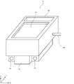
- FIG. 1 It is an external view which shows the three-dimensional model
- FIG. 10 is a flowchart showing the structure forming process of FIG. 9.
- 10 is a flowchart showing the ejection process of FIG. 9. It is a figure which shows typically operation
- the three-dimensional modeling apparatus 1 receives coordinate data, color data, and the like for three-dimensional modeling printing created by a PC 200 that is a personal computer via a network 300. Based on the received coordinate data and color data, the three-dimensional modeling apparatus 1 discharges a modeling liquid from the inkjet head 21 to the powder material on the stage 5 to create a three-dimensional modeled object.
- the three-dimensional modeling apparatus 1 has a substantially rectangular parallelepiped housing 2 having the X-axis direction as a longitudinal direction, and two rails 3 extending in the Y-axis direction that is the front-rear direction of the housing 2 at the substantially center of the bottom surface. Are arranged (see FIG. 3).
- the two rails 3 are respectively supported by a support portion 31 provided on the Y-axis negative side, which is the front side of the housing 2 in FIG. 1, and a support portion on the Y-axis positive side (not shown).
- the rail 3 is inserted through a through hole 14 (see FIG. 4) of the stage support base 12, and the stage support base 12 can move along the rail 3 in the Y-axis direction.
- the stage drive motor 57 of FIG. 8 is provided at the end in the positive Y-axis direction of the rail 3 behind the housing 2 of FIG. 1.
- the stage support 12 of FIG. 4 is reciprocated in the Y-axis direction along the rail 3 via the carriage belt by the drive of the stage drive motor 57.
- the stage 5 fixed to the upper portion of the stage support 12 moves in the Y-axis direction.
- a powder recovery port 87 of FIGS. 3 and 4 for recovering the excess powder moved by the roller 8 is provided in the positive Y-axis direction behind the housing 2 of the stage 5. The powder material charged into the powder recovery port 87 is recovered to the powder recovery unit 85 through the recovery path 89 (see FIG. 2).
- the powder material collected in the powder collection unit 85 is input to the powder supply unit 7 by the user.
- the powder supply unit 7 may be automatically recharged by a suction mechanism (not shown).
- the elevating plate 51 is provided so as to be movable in the Z-axis direction within the cavity 56 of the stage 5.
- the elevating plate 51 moves from the same position as the upper surface of the stage 5 in the Z coordinate range of the three-dimensional structure to be formed.
- a ball screw 54 for supporting the lifting plate 51 is provided at the center of the lower surface of the lifting plate 51.
- the elevating plate 51 is moved in the Z-axis direction inside the hollow portion 56 by rotating the ball screw 54 by driving the elevating plate motor 53 of FIG.
- the ball screw 54 is provided via a bearing by a support member (not shown) in the cavity 56 of the stage 5 via the lifting plate motor 53 of FIG.
- a guide rail 9 for guiding the movement of the inkjet head 21 in the X-axis direction is installed at the approximate center in the Y-axis direction of the housing 2 and above the stage 5.
- a head motor 24 (see FIG. 8) provided near the end of the guide rail 9 on the left side of the casing 2 on the left side of the X axis and the end of the right side of the casing 2 near the end of the positive side of the X axis.
- a carriage belt is installed across the X-axis direction of the housing 2 between the pulley (not shown) provided.
- the carriage belt is driven via the head motor 24 in FIG. 8 so that the inkjet head 21 is reciprocated in the X-axis direction of the housing 2.
- the three-dimensional modeling apparatus 1 can create a three-dimensional modeled object, and cyan ink, magenta ink, yellow ink, black ink, and clear ink for three-dimensional modeling are used.
- an ink storage unit 30 that stores each ink is provided on the X-axis negative side in the frame 22 of the three-dimensional modeling apparatus 1.
- the ink storage unit 30 is connected to the ink jet heads 21 of the respective colors via the ink supply tube 10.
- the ink supply tube 10 is a flexible tube made of polyethylene or the like, and has flexibility such that bending or twisting occurs in the three-dimensional modeling apparatus 1 in response to the movement of the inkjet head 21 or the like.
- the inkjet head 21 includes ejection channels (not shown) for ejecting each ink in FIG.
- Each ejection channel is provided with a piezoelectric actuator that is individually driven.
- the piezoelectric actuator is controlled so that ink droplets are ejected downward from a fine ejection nozzle provided in the bottom surface of the inkjet head 21 corresponding to each ejection channel.
- a head suction mechanism having a suction cap that can be brought into close contact with and detached from the nozzle surface of each inkjet head 21 at a position where the inkjet head 21 has moved to the retracted position on the left end on the X axis negative side of the guide rail 9. 23 is provided.
- the head suction mechanism 23 has a suction pump and a cap (not shown).
- the head suction mechanism 23 is configured to be movable up and down in the Z-axis direction by an elevator mechanism (not shown).
- an elevator mechanism not shown.
- the raised head suction mechanism 23 is in close contact with the surface of the inkjet head 21 and performs suction until the modeling liquid of each color reaches the discharge port of the inkjet head 21.
- each suction cap is in close contact with the inkjet head 21, ink can be sucked through the suction cap connected to the pump. Further, when printing is not performed, the nozzle face of the inkjet head 21 is covered with the suction cap, thereby preventing the ink from drying.
- the powder supply unit 7 in FIGS. 1 to 3 and FIG. 6 is a box-shaped container for storing a powder material used for three-dimensional modeling, and is on the X axis positive side above the stage 5 and on the right side of the housing 2. Is supported by a fixing member (not shown) on the wall surface of the powder recovery unit 85 provided on the wall. The powder material is charged by the user through the open charging port above the powder supply unit 7.
- the powder supply unit 7 includes an opening 71 at the lower portion of the powder supply unit 7 so that the powder material can be supplied to the entire region extending linearly in the X-axis direction on the stage 5 (see FIG. 6). Therefore, the opening 71 extends in the X-axis direction of the stage 5 and has substantially the same length as the length of the stage in the X-axis direction.
- the opening 71 of the powder supply unit 7 has a shutter member (not shown).
- the shutter member is moved via the shutter motor 72 of FIG. 8 and the opening 71 is opened.
- a predetermined amount of the powder material is dropped onto the stage 5.
- the shutter member closes the opening 71 by the shutter motor 72.
- the roller 8 is provided for flattening the powder material supplied on the stage 5. As shown in FIGS. 3 and 6, the roller 8 is rotated in the direction of arrow B, which is counterclockwise in FIG. 6, by a roller motor 83 (see FIG. 8) connected to the rotation shaft 81.
- the roller is fixed to the wall portion of the powder recovery unit 85 provided on the X axis positive side by a fixing member via a bearing (not shown) so that the rotation shaft 81 can rotate (see FIGS. 1 and 2). .
- the blade 82 is provided to remove the powder material adhering to the roller 8 and has a flat plate shape.
- the tip of the blade 82 facing the roller 8 is in contact with the surface of the roller 8 so as to press it.
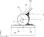
- the position where the blade 82 contacts the roller 8 is a position L2 below the rotation center C.
- a straight line L1 is a position in the Z-axis direction of the rotation center C
- a straight line L2 is a tangent line where the blade is in contact with the roller.
- the powder material of the stage 251 falls over the flattened region M1 that has been flattened over the end of the roller 208 and the blade 282. That is, even if the roller 208 is flattened, the flattened region M1 may be non-uniform.
- the position where the blade 82 contacts the roller 8 is a position L2 below the rotation center.
- the powder material removed by the blade 82 falls to the non-planarized region M2 on the stage 51, so that the powder material can be prevented from being deposited on the surface of the roller 8. That is, since it is possible to prevent excess powder material from scattering in the flattened region M1, it is possible to improve the formability of the three-dimensional structure. Note that both the roller 8 in FIG. 7A and the roller 208 in FIG. 7B rotate in the arrow B direction.
- the blade 82 is fixed to the powder supply unit 7 by a fixing unit 84 on the side opposite to the side facing the roller 8. At this time, the position where the blade 82 is fixed to the powder supply unit 7 is disposed closer to the flattened region than the opening 71.
- the blade 82 is connected between the roller 8 and the powder supply unit 7 without a gap. Therefore, even when the powder material is scattered when the powder material is flattened by the roller 8, the blade 82 can prevent the powder material from scattering in the flattening region M1.
- the blade 82 is preferably made of a conductive material. This is to reduce the adhesion of the powder material to the blade 82 due to static electricity.
- the blade 82 corresponds to the powder removing plate of the present invention. Further, the blade 82 and the roller 8 correspond to the flattening portion of the present invention.
- an operation panel 28 for operating the three-dimensional modeling apparatus 1 is provided on the front surface of the frame portion 22 on the X axis positive side of the housing 2.
- the operation panel 28 is provided with various lamps and a display.
- the operation panel 28 is provided with various buttons for operating instructions.
- the electrical configuration of the three-dimensional modeling apparatus 1 of the present embodiment will be described with reference to FIG.
- the three-dimensional modeling apparatus 1 is provided with a CPU 110 that performs main control of the three-dimensional modeling apparatus 1, and a ROM 120 and a flash RAM 130 are connected to the CPU 110 via a bus 190.
- the control unit 40 includes a CPU 110, a ROM 120, and a flash RAM 130.
- the CPU 110 performs various calculations and processes in cooperation with flash RAM 130 and ROM 120.
- the ROM 120 stores a control program for controlling the operation of the three-dimensional modeling apparatus 1, a print execution program for executing print processing, and the like.
- the flash RAM 130 stores coordinate data received from the PC 200 via the communication control unit 160.
- the coordinate data includes color data associated with the coordinate data.
- the CPU 110 is connected to the head drive unit 140, the motor drive unit 150, and the communication control unit 160 via the bus 190.
- the head driving unit 140 drives a piezoelectric actuator (not shown) provided in each ejection channel of the inkjet head 21 that ejects ink.
- the head driving unit 140 determines the ejection timing of the modeling liquid and the color of the modeling liquid to be ejected according to the ejection signal and color data from the CPU 110.
- the determined color of the modeling liquid is supplied to the inkjet head 21 as a color selection signal.
- the inkjet head 21 discharges the modeling liquid from the head of the color to be discharged among the heads of the respective colors according to the color selection signal.
- the motor drive unit 150 controls and drives the head motor 24, the stage drive motor 57, the lifting plate motor 53, the roller motor 83, and the shutter motor 72, respectively.
- the head motor 24 drives a carriage (not shown) on which the inkjet head 21 is mounted. As a result, the inkjet head 21 moves in the X-axis direction (see FIGS. 1 and 2).
- the stage drive motor 57 drives a stage roller (not shown) that adjusts the timing and speed at which the stage 5 on which the powder material is placed is sent out. As a result, the stage 5 moves in the Y-axis direction (see FIG. 3).
- the stage drive motor 57 and the motor drive unit 150 correspond to the moving mechanism of the present invention.
- the elevating plate motor 53 moves the elevating plate 51 in the Z-axis direction by rotating the ball screw 54 that supports the elevating plate 51 (see FIG. 1).
- the roller motor 83 rotates the roller 8 in a predetermined direction by rotating the rotating shaft 81 of the roller 8.
- the roller 8 is rotated in the direction of arrow B in FIG.
- the shutter motor 72 moves a shutter (not shown) that closes the opening 71 in FIG. As the shutter moves, the opening 71 of the powder supply unit 7 is opened or closed. When the opening 71 is opened, the powder material in the powder supply unit 7 is dropped onto the stage 5.
- These motors are stepping motors with built-in encoders, and can detect the amount of movement, origin position, rotational speed, and the like.
- the detected data such as the movement amount, the origin position, and the rotation speed are transmitted to the CPU 110 via the bus 190.
- the CPU 110 transmits a signal for driving to the motor driving unit 150 based on the transmitted data.
- the CPU 110 is connected to the communication control unit 160, the operation panel 28, and the head suction mechanism 23 via the bus 190.
- the communication control unit 160 performs communication between the three-dimensional modeling apparatus 1 and the outside. Necessary print data is received from the PC 200 as an external device via the communication control unit 160 and stored in the flash RAM 130.
- the operation panel 28 has various input buttons for accepting operations such as starting, stopping, and starting printing of the three-dimensional modeling apparatus 1 from the user.
- An operation from the user input to the operation panel 28 is transmitted to the CPU 110 as an operation signal (see FIG. 1).
- the head suction mechanism 23 moves up and down in the Z-axis direction, attaches a cap to the ink jet head 21 in FIG. 5, and sucks the ink jet head 21 in accordance with a signal from the CPU 110.
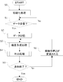
- step S0 (hereinafter referred to as S0). Specifically, suction is performed by the head suction mechanism 23 until the modeling liquid reaches a plurality of discharge ports on the lower surface of the inkjet head 21 (see FIG. 1). By this suction, the ink jet head 21 can be ejected.
- the lift plate 51 shown in FIG. 1 is moved in the Z-axis negative direction through the motor drive unit 150 and the lift plate motor 53 of FIG. Move in the direction.
- the Z coordinate moving in the Z negative direction corresponds to the thickness of the first layer of the three-dimensional structure.
- the thickness is about 100 ⁇ m.
- S1 it is determined whether or not coordinate data has been received from the PC 200.
- the coordinate data is stored in the flash RAM 130 (S2). If it is determined that the coordinate data has not been received (S1: No), since the data regarding the three-dimensional structure is not supplied to the control unit 40 by the user via the PC 200 and the bus 190, a loop standby is performed.
- the process proceeds to the next S3.
- the coordinate data having the smallest Z coordinate among the Z coordinates of the coordinate data stored by the flash RAM 130 is designated as the current coordinate position Z.
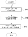
- a structure forming process is performed in S3.
- this structure forming process at least one layer of powder material at the coordinate position Z on the stage 5 is supplied. Further, the powder material supplied to the stage 5 is flattened.
- a discharge process is performed.
- the modeling liquid is discharged onto the powder material supplied to the stage 5.
- the powder material is dissolved in the modeling liquid and bonded to each other.
- one layer of the three-dimensional structure to be formed is formed.
- combined modeling with the lower layer is also performed.
- the three-dimensional model is colored simultaneously with modeling in S4.
- S5 it is determined whether or not the modeling is finished. If it is determined that the modeling is not completed (S5: No), the process proceeds to S6.
- the process proceeds to S ⁇ b> 6, the current coordinate position Z is changed to the coordinate position Z next to the current coordinate position Z among the coordinate positions Z stored in the flash RAM 130. Then, the lift plate 51 is moved in the Z-axis negative direction via the motor drive unit 150 and the lift plate motor 53 in accordance with the coordinate position. Then, the process proceeds to S5 structure formation processing.
- this flow is finished. Specifically, it is determined that the modeling is finished when a command to turn off the power is supplied to the control unit 40 or when the processing for all the coordinate positions Z stored in the flash RAM 42 is completed.
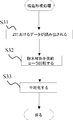
- data at the current coordinate position Z is read from the flash RAM 130 in S31.
- the data to be read is the coordinate data of the coordinates (X, Y) at the coordinate position Z.
- a powder supply process is performed.
- the opening 71 of the powder supply unit 7 is opened by the movement of the shutter, and is supplied linearly in the X-axis direction to one end of the stage 5.
- the amount of the powder material to be supplied is adjusted to the amount to which the powder material is supplied for all the coordinates (X, Y) of the molding region on the stage 5 at the current coordinate position Z.
- roller 8 is rotated by driving the roller motor 83 (see FIGS. 1 and 8).
- the number of rotations of the roller 8 is about 5 rps as an example.
- movement control of the stage 5 in the Y-axis direction is performed to flatten the powder material.
- the stage 5 moves in the negative Y-axis direction by driving the motor driving unit 150 and the stage driving motor 57 of FIG.
- the roller 8 moves horizontally in the Y-axis direction from one end of the stage 5 to the other end.
- the moving speed of the stage 5 is about 50 to 300 mm / s.
- the inkjet head 21 of FIG. 1 is moved by a predetermined distance in the X-axis direction via the motor driving unit 150 and the head motor 24 of FIG.
- the modeling liquid is discharged by the inkjet head 21 based on the discharge signal from the control unit 40 with respect to predetermined coordinates.
- the inkjet head 21 is moved in the X-axis direction via the head motor 24. These are moved and discharged in accordance with the position coordinate data of the three-dimensional structure stored in the flash RAM 130.
- the stage drive motor 57 is driven to move the stage 5 in the positive direction of the Y axis (see FIGS. 1 and 8). That is, the reciprocation of the inkjet head 21 in the X-axis direction is performed line by line, and when the reciprocation of the inkjet head 21 in the X-axis direction is completed by one line, the stage 5 is moved to a predetermined next line in the positive Y-axis direction. Moved. In this way, the inkjet head 21 is relatively moved line by line in the X-axis direction from the initial position toward the positive Y-axis direction.
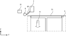
- FIG. 12A when the lifting plate motor 53 of FIG. 8 is first driven, the lifting plate 51 is lowered from the same position as the surface of the stage 5 to a predetermined Z coordinate position in the negative Z-axis direction, which is the arrow A direction.
- the position in FIG. 12A is the initial position of the stage 5.
- the shutter motor 72 is driven to open the opening 71 (see FIGS. 6 and 8), whereby the powder material is supplied onto the stage 5 from the powder supply unit 7.
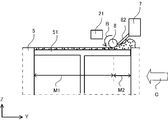
- the rotation of the roller 8 in the arrow B direction is started.
- the movement of the stage 5 in the negative Y-axis direction which is the direction of arrow C, is started.
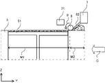
- the arrangement of the roller 8 and the powder supply unit 7 is fixed, and when the stage 5 moves, both the roller 8 and the powder supply unit 7 move relative to the stage 5. If the powder supply part 7 moves with the stage 5, the powder supply part 7 may be arrange
- the roller 8 and the powder supply unit 7 are both relatively moved with respect to the stage 5, so that the powder supply unit 7 is always arranged on the non-planarized region M2.
- the powder supply unit 7 is always arranged on the non-planarized region M2.
- the stage 5 moves in the positive direction of the Y-axis and moves to the origin position, a series of operations is repeated to form a three-dimensional modeled object.
- the roller 8 and the powder supply unit 7 move relative to the stage 5 by moving the stage 5 in the Y-axis direction, but the present invention is not limited to this.
- the arrangement of the stage 5 may be fixed, and the roller 8 and the powder supply unit 7 may move together.
- the blade 82 is fixed to the powder supply unit 7 so that there is no gap between the roller 8 and the powder supply unit 7, but the blade 82 and the powder supply unit 7 are fixed. It does not have to be.
- a support member for supporting and fixing the blade 82 may be provided separately.
- a heating unit for heating the roller 8 may be provided.
- the powder in the lower layer to which the modeling liquid adheres temporarily adheres to the roller 8, it is possible to prevent the modeling liquid from evaporating by heating and prevent the powder material from accumulating between the roller and the blade. Thereby, it can prevent that powder material accumulates between a roller and a blade, and powder falls to the flattening area
Landscapes
- Chemical & Material Sciences (AREA)
- Engineering & Computer Science (AREA)
- Materials Engineering (AREA)
- Physics & Mathematics (AREA)
- Manufacturing & Machinery (AREA)
- Mechanical Engineering (AREA)
- Optics & Photonics (AREA)
Abstract
L'invention concerne un appareil de façonnage en trois dimensions destiné à façonner un objet en trois dimensions avec une haute précision dimensionnelle tout en empêchant un matériau en poudre de s'éparpiller dans une région d'aplatissement lors d'une section lorsque le matériau en poudre est aplati au moyen d'un rouleau. L'appareil de façonnage en trois dimensions comprend : une unité de fourniture de poudre destinée à fournir un matériau en poudre lors à une section ; un rouleau rotatif destiné à aplatir le matériau en poudre fourni par l'unité de fourniture de poudre ; une unité d'aplatissement disposée en une position faisant face au rouleau et comprenant une plaque de retrait de poudre destinée à retirer le matériau en poudre du rouleau ; et un mécanisme d'actionnement déplaçant l'unité d'aplatissement par rapport à la section pour l'aplatissement du matériau en poudre, l'appareil de façonnage en trois dimensions étant caractérisé en ce que : lorsque le mécanisme d'actionnement actionne l'unité d'aplatissement pour aplatir le matériau en poudre, le matériau en poudre fourni à la section comprend une région aplatie qui est aplatie par l'unité d'aplatissement et une région non aplatie qui n'est pas encore aplatie par la région d'aplatissement, et la plaque de retrait de poudre est placée dans la région non aplatie et entre en contact avec le rouleau en une position inférieure à celle du centre de rotation du rouleau.
Applications Claiming Priority (2)
| Application Number | Priority Date | Filing Date | Title |
|---|---|---|---|
| JP2011-030474 | 2011-02-16 | ||
| JP2011030474A JP5408151B2 (ja) | 2011-02-16 | 2011-02-16 | 立体造形装置 |
Publications (1)
| Publication Number | Publication Date |
|---|---|
| WO2012111382A1 true WO2012111382A1 (fr) | 2012-08-23 |
Family
ID=46672322
Family Applications (1)
| Application Number | Title | Priority Date | Filing Date |
|---|---|---|---|
| PCT/JP2012/051173 Ceased WO2012111382A1 (fr) | 2011-02-16 | 2012-01-20 | Appareil de façonnage en trois dimensions |
Country Status (2)
| Country | Link |
|---|---|
| JP (1) | JP5408151B2 (fr) |
| WO (1) | WO2012111382A1 (fr) |
Cited By (2)
| Publication number | Priority date | Publication date | Assignee | Title |
|---|---|---|---|---|
| US20160176119A1 (en) * | 2014-12-17 | 2016-06-23 | Xerox Corporation | System For Planarizing Objects In Three-Dimensional Object Printing Systems With Reduced Debris |
| WO2017196337A1 (fr) * | 2016-05-12 | 2017-11-16 | Hewlett-Packard Development Company, L.P. | Appareils d'étalement de matériau de construction pour fabrication additive |
Families Citing this family (13)
| Publication number | Priority date | Publication date | Assignee | Title |
|---|---|---|---|---|
| JP6379684B2 (ja) | 2014-06-02 | 2018-08-29 | 株式会社リコー | 立体造形装置 |
| DE102014112469A1 (de) | 2014-08-29 | 2016-03-03 | Exone Gmbh | Beschichteranordnung für einen 3d-drucker |
| DE102014112450A1 (de) | 2014-08-29 | 2016-03-03 | Exone Gmbh | Beschichteranordnung für einen 3D-Drucker |
| JP6554951B2 (ja) * | 2014-09-09 | 2019-08-07 | 株式会社リコー | 立体造形装置 |
| US9592637B2 (en) * | 2015-05-19 | 2017-03-14 | Xerox Corporation | Direct marking build cart that is robust to rail contamination by under-rail mounting and compliant top wheel |
| JP6620505B2 (ja) * | 2015-10-19 | 2019-12-18 | 株式会社リコー | 粉末積層造形装置及び粉体層の製造方法 |
| CN105386039B (zh) * | 2015-11-13 | 2017-12-01 | 上海工程技术大学 | 一种用于调节激光熔覆预置粉层厚度的压平装置 |
| JP6624901B2 (ja) * | 2015-11-19 | 2019-12-25 | ローランドディー.ジー.株式会社 | 三次元造形装置 |
| JP6653586B2 (ja) * | 2016-02-04 | 2020-02-26 | 株式会社Fuji | 3次元造形装置 |
| KR101676606B1 (ko) * | 2016-04-06 | 2016-11-16 | 주식회사 대건테크 | 3d 프린터용 분말 공급장치 |
| JP2018192656A (ja) * | 2017-05-15 | 2018-12-06 | ローランドディー.ジー.株式会社 | 三次元造形装置 |
| EP3695922B1 (fr) * | 2017-10-13 | 2024-04-24 | IHI Corporation | Dispositif de fabrication additive tridimensionnel comprenant un dispositif d'alimentation en poudre |
| WO2023248523A1 (fr) * | 2022-06-21 | 2023-12-28 | ローランドディー.ジー.株式会社 | Appareil de mise en forme tridimensionnelle |
Citations (2)
| Publication number | Priority date | Publication date | Assignee | Title |
|---|---|---|---|---|
| JPH11513328A (ja) * | 1995-09-27 | 1999-11-16 | スリーディー システムズ インコーポレーテッド | 選択積層造形システムにおけるデータ操作およびシステム制御の方法および装置 |
| JP2001334581A (ja) * | 2000-05-24 | 2001-12-04 | Minolta Co Ltd | 三次元造形装置 |
-
2011
- 2011-02-16 JP JP2011030474A patent/JP5408151B2/ja not_active Expired - Fee Related
-
2012
- 2012-01-20 WO PCT/JP2012/051173 patent/WO2012111382A1/fr not_active Ceased
Patent Citations (2)
| Publication number | Priority date | Publication date | Assignee | Title |
|---|---|---|---|---|
| JPH11513328A (ja) * | 1995-09-27 | 1999-11-16 | スリーディー システムズ インコーポレーテッド | 選択積層造形システムにおけるデータ操作およびシステム制御の方法および装置 |
| JP2001334581A (ja) * | 2000-05-24 | 2001-12-04 | Minolta Co Ltd | 三次元造形装置 |
Cited By (3)
| Publication number | Priority date | Publication date | Assignee | Title |
|---|---|---|---|---|
| US20160176119A1 (en) * | 2014-12-17 | 2016-06-23 | Xerox Corporation | System For Planarizing Objects In Three-Dimensional Object Printing Systems With Reduced Debris |
| US10245786B2 (en) * | 2014-12-17 | 2019-04-02 | Xerox Corporation | System for planarizing objects in three-dimensional object printing systems with reduced debris |
| WO2017196337A1 (fr) * | 2016-05-12 | 2017-11-16 | Hewlett-Packard Development Company, L.P. | Appareils d'étalement de matériau de construction pour fabrication additive |
Also Published As
| Publication number | Publication date |
|---|---|
| JP5408151B2 (ja) | 2014-02-05 |
| JP2012166487A (ja) | 2012-09-06 |
Similar Documents
| Publication | Publication Date | Title |
|---|---|---|
| JP5408151B2 (ja) | 立体造形装置 | |
| CN102555027A (zh) | 三维造型装置、三维造型方法、通过该方法形成的模型 | |
| JP2013176893A (ja) | 立体造形装置 | |
| JP6656102B2 (ja) | 塗布装置及び塗布方法 | |
| JP2014104683A (ja) | 立体造形装置 | |
| JP2019001010A (ja) | 三次元造形装置 | |
| JP6644493B2 (ja) | 三次元造形装置 | |
| JP2013075389A (ja) | 立体造形装置 | |
| JP2010250198A (ja) | 製膜装置及び製膜方法 | |
| CN212708039U (zh) | 一种旋转式三维打印机 | |
| JP7114444B2 (ja) | 三次元造形装置 | |
| JP5392282B2 (ja) | 立体造形装置と立体造形物の製造方法 | |
| JP2014000768A (ja) | 立体造形装置 | |
| JP2013075391A (ja) | 立体造形データ作成装置および立体造形データ作成プログラム | |
| JP2015182304A (ja) | 立体造形装置およびその駆動制御方法 | |
| JP5310631B2 (ja) | 3次元造形装置、3次元造形方法、及び3次元造形プログラム | |
| CN104723565B (zh) | 一款3dp彩色三维打印机的粉末回收装置 | |
| JP5751118B2 (ja) | 立体造形装置 | |
| JP6624901B2 (ja) | 三次元造形装置 | |
| JP2017202620A (ja) | 立体造形装置 | |
| JP2013144460A (ja) | インクジェット記録装置 | |
| JP5299099B2 (ja) | インクジェット記録ヘッドユニット及びインクジェット記録装置 | |
| JP3779697B2 (ja) | 回路基板の孔埋め方法 | |
| KR20160034554A (ko) | 3차원 프린터의 배드에서 입체 조형물 분리 장치 및 방법 | |
| JP2017159556A (ja) | 立体造形物を造形する装置、プログラム、立体造形物の造形データを作成する装置 |
Legal Events
| Date | Code | Title | Description |
|---|---|---|---|
| 121 | Ep: the epo has been informed by wipo that ep was designated in this application |
Ref document number: 12747093 Country of ref document: EP Kind code of ref document: A1 |
|
| NENP | Non-entry into the national phase |
Ref country code: DE |
|
| 122 | Ep: pct application non-entry in european phase |
Ref document number: 12747093 Country of ref document: EP Kind code of ref document: A1 |