WO2012111404A1 - 画像処理装置、そのプログラム、および画像処理方法 - Google Patents
画像処理装置、そのプログラム、および画像処理方法 Download PDFInfo
- Publication number
- WO2012111404A1 WO2012111404A1 PCT/JP2012/051747 JP2012051747W WO2012111404A1 WO 2012111404 A1 WO2012111404 A1 WO 2012111404A1 JP 2012051747 W JP2012051747 W JP 2012051747W WO 2012111404 A1 WO2012111404 A1 WO 2012111404A1
- Authority
- WO
- WIPO (PCT)
- Prior art keywords
- image
- distance information
- processing apparatus
- region
- distance
- Prior art date
- Legal status (The legal status is an assumption and is not a legal conclusion. Google has not performed a legal analysis and makes no representation as to the accuracy of the status listed.)
- Ceased
Links
Images


Classifications
-
- H—ELECTRICITY
- H04—ELECTRIC COMMUNICATION TECHNIQUE
- H04N—PICTORIAL COMMUNICATION, e.g. TELEVISION
- H04N13/00—Stereoscopic video systems; Multi-view video systems; Details thereof
- H04N13/10—Processing, recording or transmission of stereoscopic or multi-view image signals
- H04N13/106—Processing image signals
- H04N13/128—Adjusting depth or disparity
-
- G—PHYSICS
- G06—COMPUTING OR CALCULATING; COUNTING
- G06T—IMAGE DATA PROCESSING OR GENERATION, IN GENERAL
- G06T5/00—Image enhancement or restoration
- G06T5/50—Image enhancement or restoration using two or more images, e.g. averaging or subtraction
-
- G—PHYSICS
- G06—COMPUTING OR CALCULATING; COUNTING
- G06T—IMAGE DATA PROCESSING OR GENERATION, IN GENERAL
- G06T5/00—Image enhancement or restoration
- G06T5/70—Denoising; Smoothing
-
- H—ELECTRICITY
- H04—ELECTRIC COMMUNICATION TECHNIQUE
- H04N—PICTORIAL COMMUNICATION, e.g. TELEVISION
- H04N13/00—Stereoscopic video systems; Multi-view video systems; Details thereof
- H04N13/20—Image signal generators
- H04N13/271—Image signal generators wherein the generated image signals comprise depth maps or disparity maps
-
- G—PHYSICS
- G06—COMPUTING OR CALCULATING; COUNTING
- G06T—IMAGE DATA PROCESSING OR GENERATION, IN GENERAL
- G06T2207/00—Indexing scheme for image analysis or image enhancement
- G06T2207/10—Image acquisition modality
- G06T2207/10016—Video; Image sequence
- G06T2207/10021—Stereoscopic video; Stereoscopic image sequence
-
- H—ELECTRICITY
- H04—ELECTRIC COMMUNICATION TECHNIQUE
- H04N—PICTORIAL COMMUNICATION, e.g. TELEVISION
- H04N2213/00—Details of stereoscopic systems
- H04N2213/003—Aspects relating to the "2D+depth" image format
Definitions
- the present invention relates to an image processing technique that uses a subject image taken from one viewpoint and generates a pseudo image whose combination with the image constitutes a stereoscopic image of the subject.
- a pseudo image has been generated in which a pseudo image of an image obtained when a subject is photographed from a virtual viewpoint different from the viewpoint where the subject is actually photographed is simulated without performing actual photographing from the virtual viewpoint.
- Generation devices are beginning to be used for purposes such as generating stereoscopic images that can be viewed stereoscopically.
- the present invention has been made to solve these problems, and an object of the present invention is to provide a technique capable of reducing image distortion occurring in a pseudo image.
- an image processing apparatus includes a first acquisition unit that acquires a reference image in which a subject is photographed, and each pixel of the reference image among the points of the subject. For each corresponding point, a second acquisition unit that acquires first distance information that represents distance information from a preset origin position, and a reduction that reduces variations in the first distance information Based on the reference image and the second distance information, a pseudo image forming a stereoscopic image by a combination of the first generation unit that generates the second distance information by processing and the reference image And when the reference image and the pseudo image are arranged so as to be stereoscopically viewable in the same image space, the reference images corresponding to the same point on the subject are mutually included.
- Pixel and said pseudo A first direction with respect to the reference image is defined by a direction of displacement in the image space with respect to an image pixel, and an original distance image is obtained by an array of the first distance information corresponding to the pixel array of the reference image.
- the first generation unit has an intensity for reducing variation in the first distance information in a second direction crossing the first direction in the original distance image. The reduction process is performed so as to be stronger than the strength for reducing the variation in the first distance information in the first direction.
- the image processing device is the image processing device according to the first aspect, wherein the first generation unit is configured to perform the first direction and the second direction.
- the reduction process is performed by performing smoothing filter processes having different smoothing intensities.
- An image processing device is the image processing device according to the first aspect, wherein the first generation unit is longer in the second direction than in the first direction.
- a vertically long block area is set in the original distance image to obtain an average value of each distance information corresponding to the block area among the first distance information, and based on the obtained average value
- the reduction process is performed by performing the process of acquiring the value of each distance information corresponding to the block area in the second distance information while moving the block area with respect to the original distance image.
- An image processing device is the image processing device according to any one of the first to third aspects, wherein the first generation unit includes the first direction in the original distance image.
- the reduction process is performed by reducing the variation of the first distance information only in the second direction of the second direction.
- An image processing device is the image processing device according to any one of the first to fourth aspects, and an image space corresponding to the original distance image based on a predetermined determination condition.
- a detection unit that detects a region of interest that may cause distortion of the pseudo image, wherein the first generation unit targets the region corresponding to the region of interest in the original distance image as the target.
- the image processing apparatus is the image processing apparatus according to the fifth aspect, wherein the detection unit detects the region of interest using the geometric condition for the reference image as the determination condition.
- the image processing apparatus is the image processing apparatus according to the sixth aspect, wherein the shape and size in the coordinate space are specified by giving specific numerical values to the parameters of the mathematical formula set in advance.
- the geometric condition is a ratio of one or more types of preset basic figures that form an outline in the reference image.
- An image processing device is the image processing device according to the seventh aspect, wherein the one or more types of preset basic figures are straight lines, quadratic curves, arcs, elliptical arcs, and presets. At least one of the textures applied.
- An image processing device is the image processing device according to the fifth aspect, wherein the detection unit uses the statistical distribution state of the first distance information as the determination condition as the region of interest. Is detected.
- An image processing apparatus is the image processing apparatus according to the fifth aspect, wherein the second acquisition unit captures the subject from a viewpoint different from the viewpoint from which the reference image was captured.
- the corresponding distance search processing between the reference image and the reference image is performed to acquire the first distance information, and the detection unit corresponds to the first distance information.
- the region of interest is detected using each correlation value acquired in the search process as the determination condition.
- An image processing apparatus is the image processing apparatus according to any one of the fifth to tenth aspects, wherein the determination condition gives a quantitative determination result regarding the possibility of causing the distortion. Including a determination rule, wherein the first generation unit determines a reduction intensity of the variation in the second direction with respect to the region of interest according to a result of the quantitative determination regarding the possibility of causing the distortion. change.
- the program according to the twelfth aspect is executed by a computer mounted on the image processing apparatus, whereby the image processing apparatus is used as the image processing apparatus according to any one of claims 1 to 11. Make it work.
- An image processing method includes a first acquisition step of acquiring a reference image in which a subject is photographed, and each point corresponding to each pixel of the reference image among the points of the subject.
- the second distance information is obtained by the second acquisition step of acquiring the first distance information expressing the distance information from the set origin position, and the reduction process for reducing the variation of the first distance information.
- the intensity of reducing variation in the first distance information in the second direction crossing the first direction in the original distance image has the strength in the first direction in the original distance image.
- the reduction process is performed so as to be stronger than the strength for reducing the variation of the first distance information.
- the variation of the second distance information regarding the second direction that is the main cause of the geometric distortion of the pseudo image is the second distance information regarding the first direction. Since the second distance information is generated so as to be smaller than the variation of the distance and the pseudo image is generated based on the second distance information, the distortion of the image generated in the pseudo image can be reduced.
- FIG. 1 is a diagram illustrating an example of a main configuration of an image processing system according to an embodiment.
- FIG. 2 is a diagram illustrating an example of a functional configuration of the image processing apparatus according to the embodiment.
- FIG. 3 is a diagram illustrating an example of a reference image.
- FIG. 4 is a diagram illustrating an example of a reference image.
- FIG. 5 is a diagram for explaining an example of parallax.
- FIG. 6 is a diagram for explaining an example of a basic method for generating a pseudo image from a reference image.
- FIG. 7 is a diagram illustrating an example of the original distance image.
- FIG. 8 is a diagram illustrating an example of the averaging filter.
- FIG. 1 is a diagram illustrating an example of a main configuration of an image processing system according to an embodiment.
- FIG. 2 is a diagram illustrating an example of a functional configuration of the image processing apparatus according to the embodiment.
- FIG. 3 is a diagram illustrating an example of a reference
- FIG. 9 is a diagram illustrating an example of a distance image smoothed with the same smoothing intensity.
- FIG. 10 is a diagram illustrating an example of a pseudo image in which distortion is not suppressed.
- FIG. 11 is a diagram illustrating an example of a region of interest.
- FIG. 12 is a diagram illustrating an example of a block area set in the original distance image.
- FIG. 13 is a diagram illustrating an example of the distribution of distance information in the block area.
- FIG. 14 is a diagram illustrating an example of a region of interest.
- FIG. 15 is a diagram illustrating an example of a region of interest.
- FIG. 16 is a diagram illustrating an example of a plurality of regions of interest.
- FIG. 17 is a diagram illustrating an example of the derived distance image.
- FIG. 18 is a diagram illustrating an example of a pseudo image in which image distortion is suppressed.
- FIG. 19 is a diagram illustrating an example of the averaging filter according to the embodiment.
- FIG. 20 is a diagram illustrating an example of the averaging filter according to the embodiment.
- FIG. 21 is a diagram illustrating an example of the averaging filter according to the embodiment.
- FIG. 22 is a diagram illustrating an example of processing for reducing variation in distance information according to the embodiment.
- FIG. 23 is a diagram illustrating an example of a correspondence relationship of each pixel in each of the partial image of the reference image and the partial image of the pseudo image.
- FIG. 24 is a diagram illustrating an example of a correspondence relationship between pixel coordinates and distance information of a reference image and pixel coordinates of a pseudo image.
- FIG. 25 is a diagram illustrating an operation flow of the image processing apparatus according to the embodiment.
- FIG. 26 is a diagram illustrating an operation flow of the image processing apparatus according to the embodiment.
- FIG. 27 is a diagram illustrating an operation flow of the image processing apparatus according to the embodiment.
- FIG. 28 is a diagram illustrating an operation flow of the basic method for generating a pseudo image.
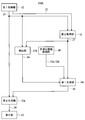
- FIG. 1 is a block diagram illustrating an example of a main configuration of an image processing system 100A according to the embodiment.
- the image processing system 100A mainly includes a stereo camera 300 and an image processing apparatus 200A.
- the image processing device 200A acquires the reference image 21 (FIGS. 1 and 2) and the reference image 22 (FIGS. 1 and 2) captured by the stereo camera 300, and the image processing device 200A acquires the reference image 21.
- the pseudo image 24 FIG. 1
- a pseudo image 24 corresponding to an image of a subject taken from another virtual viewpoint is generated.
- the pseudo image 24 constitutes a stereoscopic image that can be stereoscopically viewed in combination with the reference image 21.
- the stereo camera 300 mainly includes a base camera 61 and a reference camera 62.
- the reference camera 61 and the reference camera 62 are mainly configured by an imaging optical system and a control processing circuit (not shown), respectively.
- the reference camera 61 and the reference camera 62 are provided with a predetermined base line length in the vertical direction, and process light information from a subject incident on the photographing optical system in synchronization with a control processing circuit or the like.
- the reference image 21 (FIGS. 1 and 3) and the reference image 22 (FIGS. 1 and 4), which are digital images of a predetermined size such as 3456 ⁇ 2592 pixel size, for example, constituting a stereo image of the subject are generated. .
- Various operations of the stereo camera 300 are controlled based on control signals supplied from the image processing apparatus 200A via the input / output unit 41 and the communication line DL.
- the communication line DL may be a wired line or a wireless line.
- the stereo camera 300 is configured to be able to generate a plurality of reference images 21 and a plurality of reference images 22 by continuously photographing a subject in time sequence while synchronizing the reference camera 61 and the reference camera 62.
- the standard image 21 and the reference image 22 may be color images or monochrome images.
- the generated standard image 21 and reference image 22 are supplied to the input / output unit 41 of the image processing apparatus 200A via the communication line DL.
- the image processing apparatus 200 ⁇ / b> A generates first distance information 27 (FIG. 2) that is distance information about the subject based on the standard image 21 and the reference image 22, and further includes the standard image 21 and the first distance information.
- a pseudo image 24 (FIG. 2) is generated on the basis of the second distance information 28 (FIG. 2) generated from 27.
- the image processing apparatus 200 ⁇ / b> A mainly includes a CPU 11 ⁇ / b> A, an input / output unit 41, an operation unit 42, a display unit 43, a ROM 44, a RAM 45, and a storage device 46. This is realized by executing a program on a computer.
- the input / output unit 41 includes an input / output interface such as a USB interface or a Bluetooth (registered trademark) interface, an interface for connecting to a LAN or the Internet such as a multimedia drive and a network adapter, and the like. Exchange data between the two.
- the input / output unit 41 supplies, for example, various control signals for the CPU 11A to control the stereo camera 300 to the stereo camera 300 connected to the input / output unit 41 via the communication line DL or the like. To do.
- the input / output unit 41 also supplies the standard image 21 and the reference image 22 captured by the stereo camera 300 to the image processing apparatus 200A.
- the input / output unit 41 also supplies the standard image 21 and the reference image 22 to the image processing apparatus 200A, for example, by receiving a storage medium such as an optical disk in which the standard image 21 and the reference image 22 are stored in advance.
- the operation unit 42 includes, for example, a keyboard or a mouse. When the operator operates the operation unit 42, setting of various control parameters for the image processing apparatus 200A and various operation modes of the image processing apparatus 200A are performed. Settings are made.
- the functional unit of the image processing apparatus 200 ⁇ / b> A is configured to perform processing according to each operation mode set from the operation unit 42.
- the display unit 43 is configured by, for example, a liquid crystal display screen for 3D display corresponding to a 3D display system such as a parallax barrier system.
- the display unit 43 includes an image processing unit (not shown) that converts a stereoscopic image composed of the reference image 21 and the pseudo image 24 into an image format corresponding to the three-dimensional display method in the display unit 43.
- the display unit 43 displays the stereoscopic image on which the necessary conversion processing has been performed by the image processing unit on the display screen.
- a three-dimensional display method in the display unit 43 for example, the left-eye image and the right-eye image are alternately switched at a high speed and displayed on the display unit 43, and each shutter corresponding to the left eye and the right eye is synchronized with the switching.
- the display unit 43 displays an image supplied from the stereo camera 300, an image generated by the image processing device 200A, various setting information about the image processing device 200A, a control GUI (Graphical User Interface), and the like as a two-dimensional image. Or as character information so that it can be viewed by an observer.
- GUI Graphic User Interface
- ROM (Read Only Memory) 44 is a read-only memory and stores a program PG1 for operating the CPU 11A.
- a readable / writable nonvolatile memory (for example, a flash memory) may be used instead of the ROM 44.
- a RAM (Random Access Memory) 45 is a readable / writable volatile memory that temporarily stores various images acquired by the image processing apparatus 200A, pseudo images generated by the image processing apparatus 200A, distance information (distance images), and the like. It functions as an image storage unit for storing, a work memory for temporarily storing processing information of the CPU 11A, and the like.
- the storage device 46 is configured by, for example, a readable / writable nonvolatile memory such as a flash memory, a hard disk device, or the like, and permanently records information such as various control parameters and various operation modes of the image processing device 200A. Further, the storage device 46 is provided with a smoothing information storage unit 48, and the smoothing information storage unit 48 stores various smoothing information for smoothing the image information of the subject. .
- the smoothing information is, for example, information that defines a smoothing filter, that is, information that specifies the type of smoothing filter, the strength of smoothing, or various information related to smoothing processing such as a program corresponding to the smoothing processing, That is, the smoothing rule.
- the smoothing information is referred to by the first generation unit 14A (FIG. 2) and used for the acquisition processing of the second distance information 28 (FIG. 2).
- a CPU (Central Processing Unit) 11A is a control processing device that controls and controls each functional unit of the image processing device 200A, and executes control and processing according to the program PG1 and the like stored in the ROM 44. As will be described later, the CPU 11A also functions as the first acquisition unit 12, the second acquisition unit 13, the first generation unit 14A, the second generation unit 15A, and the detection unit 17A.
- the CPU 11A uses these functional units and the like for the subject corresponding to the photographing from the virtual viewpoint different from the first viewpoint from the reference image 21 (FIGS. 2 and 3) for the subject photographed from the first viewpoint.
- Pseudo image 24 (FIGS. 2 and 18), that is, a pseudo image 24 constituting a stereoscopic image that can be viewed stereoscopically is generated in combination with the reference image 21.
- the CPU 11A controls the imaging operation of the stereo camera 300 and controls the display unit 43 to display various images, calculation results, various control information, and the like on the display unit 43.
- each of the CPU 11A, the input / output unit 41, the operation unit 42, the display unit 43, the ROM 44, the RAM 45, the storage device 46, and the like are electrically connected via a signal line 49. Therefore, for example, the CPU 11A can execute control of the stereo camera 300 via the input / output unit 41, acquisition of image information from the stereo camera 300, display on the display unit 43, and the like at a predetermined timing.
- each function unit of the first acquisition unit 12, the second acquisition unit 13, the first generation unit 14A, the second generation unit 15A, and the detection unit 17A is a predetermined program by the CPU 11A.
- each of these functional units may be realized by a dedicated hardware circuit, for example.
- FIG. 2 is a block diagram illustrating an example of a main functional configuration of the image processing apparatus 200A according to the embodiment.
- FIGS. 3 and 4 are diagrams illustrating examples of the standard image 21 and the reference image 22 in which the standard camera 61 and the reference camera 62 of the stereo camera 300 according to the embodiment respectively photograph a subject.
- 25 to 27 are diagrams each illustrating an operation flow of the image processing apparatus 200A according to the embodiment.
- the image processing apparatus 200 ⁇ / b> A is based on the standard image 21 and the reference image 22, and is a pseudo image 24 (corresponding to photographing a subject from a virtual viewpoint different from the first viewpoint from which the standard image 21 was photographed.
- FIG. 1 is based on the standard image 21 and the reference image 22
- the position and orientation of the stereo camera 300 Prior to shooting a subject that is a target for generating a pseudo image corresponding to shooting from a virtual viewpoint, the position and orientation of the stereo camera 300 are set so that the subject can be shot from both the reference camera 61 and the reference camera 62. Adjusted.
- the position of the reference camera 61 of the stereo camera 300 in this state is the first viewpoint. More specifically, for example, the principal point position of the photographing optical system of the reference camera 61 is the first viewpoint.
- the stereo camera 300 is supplied with a control signal.
- the photographing operation of the camera 300 is performed.
- the standard image 21 and the reference image 22 for the subjects photographed by the standard camera 61 and the reference camera 62 are generated and supplied to the input / output unit 41 of the image processing apparatus 200A.
- the first acquisition unit 12 uses the reference image 21 via the input / output unit 41. (Step S110 in the operation flow S100A of FIG. 25) and the reference image 22 is acquired.
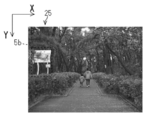
- FIGS. 3 and 4 are diagrams showing examples of the standard image 21 and the reference image 22, respectively. Since the baseline length direction of the reference camera 61 and the reference camera 62 is along the vertical direction (Y-axis direction in FIGS. 3 and 4), the reference image 21 and the reference image 22 have a parallax described later on the Y-axis. It occurs along the direction. Further, a standing signboard is photographed in the area 5a of the reference image 21.
- the standing signboard is an example of an artifact having a large number of basic graphic elements such as straight lines.
- each distance from the stereo camera 300 in each pixel of the region 5a has a wide distribution width and is a discrete distribution.
- coordinate axes are provided for ease of explanation. In other drawings of the present application, coordinate axes may be appropriately provided and used for the description.
- the acquired reference image 21 is supplied to the second acquisition unit 13, the second generation unit 15A, and the detection unit 17A.
- the reference image 22 is supplied to the second acquisition unit 13.
- the first acquisition unit 12 may acquire the reference image 21 and the reference image 22 that have been captured in advance and stored in the recording medium via the input / output unit 41.
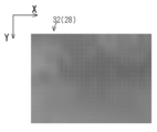
- FIG. 7 is a diagram illustrating an example of the original distance image 31 (first distance information 27) acquired by the second acquisition unit 13 (FIG. 2).
- the second acquisition unit 13 performs a corresponding point search process using a correlation calculation method or the like on the reference image 21 and the reference image 22.
- each corresponding pixel of the reference image 22 corresponding to each target pixel of the standard image 21 is specified.
- the second acquisition unit 13 determines the pixel coordinates of the target pixel in the image coordinate system of the standard image 21 and the pixels of the corresponding pixel in the image coordinate system of the reference image 22 for the target pixel and the corresponding pixel corresponding to each other.
- a process for obtaining a difference from the coordinates also referred to as “parallax” in the present application
- the parallax is an index value related to the distance from the stereo camera 300 to the point on the subject, and in this application, the term “distance information” is used as a general term for the parallax and the distance. . That is, the second acquisition unit 13 acquires first distance information 27 (FIG. 7) for points on the subject corresponding to the pixels of the reference image 21 (step S120 in FIG. 25). Further, in the first distance information 27, each parallax constituting the first distance information 27 is associated with the pixel coordinates of each pixel of the corresponding reference image 21. For this reason, each 1st distance information 27 can be acquired as the original distance image 31 etc. which were arranged according to the pixel arrangement of the standard image 21, for example.
- the first distance information 27 (original distance image 31) acquired by the second acquisition unit 13 is supplied to the detection unit 17A and the first generation unit 14A, respectively.
- the second acquisition unit 13 supplies the correlation values calculated in the process of the corresponding point search process for each of the first distance information 27 to the detection unit 17A in association with the corresponding distance information. To do.
- the corresponding point search process which specifies the corresponding pixel of the reference image 22 corresponding to the attention pixel of the standard image 21
- NCC Normalized Cross Correlation
- SAD Sud of Absolute Difference
- POC Phase Only Correlation
- the image coordinate system of the image for example, the upper left end portion of the image (for example, in the reference image 21 in FIG. 3, the image is the end in the ⁇ X direction of the image and is also the end in the ⁇ Y direction of the image. Is used as an origin, and an orthogonal coordinate system is employed in which the horizontal direction (X-axis direction) and the vertical direction (Y-axis direction) of the image are coordinate axes.
- FIG. 5 is a diagram for explaining an example of parallax between the standard image 21a and the reference image 22a.
- the reference image 21a is an example of the reference image 21 (FIG. 2) of the subject photographed by the reference camera 61, and the reference image 22a is perpendicular to the reference camera 61 (+ Y direction in FIG. 5).
- the standard image 21a and the reference image 22a are arranged in the horizontal direction (X-axis direction in FIG. 5) so that the Y coordinates of the upper end (lower end) of both images are equal to each other in order to easily grasp the parallax. Are displayed side by side.
- foreground subject images 66a and 66b of the same near subject located in the + Z direction with respect to the stereo camera 300 are respectively photographed, and for the stereo camera 300, respectively.
- Distant view subject images 67a and 67b are photographed for the same far-side subject that is further in the + Z direction than the near-side subject.
- FIG. 5 only the edge (contour) of each characteristic part in each subject image is displayed for easy explanation.
- the pixel 68a on the foreground subject image 66a and the pixel 68b on the foreground subject image 66b are pixels corresponding to the same point of the near-side subject, respectively
- the pixel 69b is a pixel corresponding to the same point of the far-side subject.
- the parallax 9a is a parallax about the pixel 68a and the pixel 68b
- the parallax 9b is a parallax about the pixel 69a and the pixel 69b.
- the parallax 9a and the parallax 9b have different values due to the difference in distance between the near subject and the far subject with respect to the stereo camera 300.
- the size of the parallax 9a corresponding to the near subject is larger than that of the parallax 9b corresponding to the far subject.
- the magnitude of the parallax varies according to the distance from the stereo camera 300 of the point on the subject corresponding to the pixel on the image.
- the positions of the principal points of the base camera 61 and the reference camera 62 are in the same plane parallel to the XY plane, the focal lengths are equal, and the optical axes of the base camera 61 and the reference camera 62 are the same.
- the image sensors of the base camera 61 and the reference camera 62 are parallel to each other along the Z axis and are on the same plane perpendicular to the optical axis, and the scanning lines are parallel to each other between the image sensors.
- the image processing device 200A is stored in the storage device 46 for the standard image 21a and the reference image 22a.
- the Z-axis direction between the principal point of the reference camera 61 and the object point on the subject corresponding to one pixel on the reference image 21a Is a parallax d between the one pixel and another pixel on the reference image 22a corresponding to the one pixel
- a focal distance fr between the base camera 61 and the reference camera 62 (more precisely, (Distance between the point and the image sensor) and the base line length b between the base camera 61 and the reference camera 62 are given by equation (1).
- the parallax is an index value regarding the distance from the stereo camera 300 of the point on the subject.
- FIG. 6 generates a pseudo image 24c constituting a stereoscopic image by combining with the reference image 21a based on the parallax and the reference image 21a for the reference image 21a and the reference image 22a shown in FIG. It is a figure for demonstrating one example of a basic method.
- the pseudo image 24c is an example of the pseudo image 24 (FIG. 2) corresponding to shooting of a subject from a virtual viewpoint different from the first viewpoint at which the reference image 21a was shot.
- the reference image 21a and the pseudo image 24c are displayed on the image display unit of the display unit 43 in a predetermined manner that allows stereoscopic viewing so as to form a stereoscopic image.
- the virtual viewpoint corresponding to the pseudo image 24c in FIG. 6 is separated from the first viewpoint in which the reference image 21a is photographed in the + X direction along the X axis by the baseline length of the reference camera 61 and the reference camera 62. Exists in the position. Accordingly, in the reference image 21a and the pseudo image 24c, the first direction described above is the X-axis direction.
- the foreground subject image 66c and the foreground subject image 67c in the pseudo image 24c correspond to the foreground subject image 66a and the foreground subject image 67a in the reference image 21a, respectively.
- the pixel 68a on the foreground subject image 66a corresponds to the pixel 68c on the foreground subject image 66c
- the pixel 69a on the far view subject image 67a corresponds to the pixel 69c on the far view subject image 67c.
- FIG. 6 as in FIG. 5, only the edges (contours) of the characteristic portions in the respective subject images are displayed and the parallax can be easily grasped for easy explanation. Therefore, the reference image 21a and the pseudo image 24c are displayed side by side in the vertical direction (Y-axis direction in FIG. 6) so that the X coordinates of the left end (right end) are equal.
- the parallax 9a between the pixel 68a and the pixel 68b in FIG. 5 is set as the parallax between the pixel 68a of the reference image 21a and the pixel 68c of the pseudo image 24c, and the pixel 69a of the reference image 21a and the pseudo image
- the parallax 9b between the pixel 69a and the pixel 69b in FIG. 5 is set as the parallax with the 24c pixel 69c.
- the parallaxes 9a and 9b between the reference image 21a and the pseudo image 24c are respectively generated in the first direction, that is, the X-axis direction.
- the parallax between the other pixels of the pseudo image 24c and the pixels of the reference image 21a is set in the same manner, whereby the parallax of each pixel of the pseudo image 24c with each pixel of the reference image 21a is acquired.
- the pseudo image 24c is acquired by deforming the reference image 21a based on the acquired parallax.
- FIG. 28 exemplifies the operation flow S10 of the basic method described above when generating the pseudo image 24c (FIG. 6) based on the reference image 21a (FIG. 6) and the distance information about each pixel of the reference image 21a.
- FIG. 28 exemplifies the operation flow S10 of the basic method described above when generating the pseudo image 24c (FIG. 6) based on the reference image 21a (FIG. 6) and the distance information about each pixel of the reference image 21a.
- a portion corresponding to one line in the first direction that is, the horizontal scanning direction (X-axis direction), at the upper end ( ⁇ Y direction end) of the reference image 21a (FIG. 6).
- the image 23a (FIG. 23) is selected (step S20).
- FIG. 23 shows a part of each pixel 7a to 7j of the partial image 23a (FIG. 23) for one line in the horizontal scanning direction (X-axis direction) at the upper end ( ⁇ Y direction end) of the reference image 21a (FIG. 6).
- the partial image 23a and the partial image 23b correspond to the same part of the subject, respectively.
- each of the pixels 7a to 7j and each of the pixels 8a to 8j is displayed by being classified for each pixel by shading according to the pixel value.
- FIG. 24 shows an example of the correspondence between the pixel coordinates and parallax (distance information) of the pixels 7a to 7j of the partial image 23a (FIG. 23) and the pixel coordinates of the pixels 8a to 8j of the partial image 23b (FIG. 23).
- FIG. The first row and the fifth row in FIG. 24 show pixel numbers that specify the respective pixels 7a to 7j of the partial image 23a and pixel numbers that specify the respective pixels 8a to 8j of the partial image 23b.
- the X coordinate of each of the pixels 7a to 7j is shown in correspondence with the pixel number shown in the first row.
- the parallax corresponding to the pixels 7a to 7j among the parallaxes (distance information) calculated for the base image 21a and the reference image 22a (FIG. 5) is shown in the first row. The corresponding pixel number is shown.
- step S20 of FIG. 28 when the partial image 23a for one line is selected, for each pixel of the selected partial image 23a, the corresponding pixel in the pseudo image 24c, that is, the pixels 8a to 8j of the partial image 23b. Pixel coordinates (X coordinates) in the horizontal scanning direction (X axis direction) are acquired (step S30 in FIG. 28).
- the virtual viewpoint corresponding to the pseudo image 24c is along the X axis with respect to the first viewpoint in which the reference image 21a (FIGS. 5 and 6) is captured.
- This is a method when the base camera 61 and the reference camera 62 are separated from each other in the + X direction by a base line length. Accordingly, the pixel coordinates (Y coordinate) in the vertical direction (Y-axis direction) of the partial image 23a and the partial image 23b are the same. Further, the parallax shown in the third row in FIG. 24 is also the parallax between the partial image 23a and the partial image 23b.
- the X coordinate of each pixel of the partial image 23b is calculated by the equation (2).
- the X coordinates of the pixels 8a to 8j calculated by the equation (2) are shown in association with the pixel numbers shown in the fifth row.
- step S40 the processing in step S40 will be described using the pixels 7a to 7j of the partial image 23a and the pixels 8a to 8j of the partial image 23b shown in FIG. 23 as examples.
- each pixel 7a, 7b, 7c, 7d, 7e, 7f, 7g, 7h, 7i, 7j of the partial image 23a is This corresponds to each pixel 8a, 8b, 8b, 8c, 8d, 8d, 8e, 8g, 8i, 8j of the partial image 23b. That is, each of the pixels 8a to 8j includes a first type pixel corresponding to one pixel among the pixels 7a to 7j, a second type pixel corresponding to two pixels, and the pixels 7a to 7j. There are three types of pixels, the third type of pixels, that none of the pixels 7j correspond to.
- the pixel value of the pixel of the partial image 23a corresponding to the pixel is adopted as the pixel value of the first type pixel, and the pixel value of the second type pixel is used.
- a representative value for example, an average value of the two pixel values of the partial image 23a corresponding to the pixel is employed.
- the pixel value of the third type pixel for example, among the pixels of the partial image 23b in which the pixel value is acquired based on the correspondence with the partial image 23a, the third type pixel is most spatially related.
- the pixel value of a close pixel is adopted.
- the image of the partial image 23b is specified by the pixel coordinate (X coordinate) specified for each pixel of the partial image 23b and the pixel value.
- step S40 it is confirmed whether or not the process (steps S30 to S40) for generating the corresponding partial image of the pseudo image is completed for all the horizontal lines (X-axis direction) of the reference image 21a.
- Step S50 in FIG. 28 As a result of the confirmation in step S50, if the processing has not been completed for all the horizontal lines, the next line in the + Y direction of the processed line in the reference image 21 is selected as a new processing target ( In step S60 of FIG. 28, the process returns to step S30. Further, as a result of the confirmation in step S50, if the process of generating the partial image of the pseudo image is completed for all the horizontal lines, the generation process of the pseudo image 24c is ended.
- the deformation of the reference image 21 (FIG. 2) based on the parallax may be performed using the pixel size as the minimum unit. Therefore, if the parallax is acquired in units of pixel size, the pseudo image 24 (FIG. 2) can be acquired. For example, the parallax can be subtracted by performing corresponding point search for determining the parallax in units of sub-pixels equal to or smaller than the pixel size. Even if acquired in units of pixels, the pseudo image 24 can be acquired if the amount of deformation is performed in units of pixels when the reference image 21 is deformed based on parallax, so that the usefulness of the present invention is not impaired.
- the baseline lengths of the virtual viewpoint and the first viewpoint related to the capture of the reference image 21 are different from the baseline lengths of the reference camera 61 and the reference camera 62 corresponding to the reference image 21 and the reference image 22, respectively.
- a pseudo image acquisition method in this case will be described.
- the distance of each point of the subject corresponding to each point is calculated from the parallax of each point of the reference image 21, using the equation (1), and the calculated distance and the virtual viewpoint
- the parallax between each pixel of the reference image 21 and each pixel of the pseudo image 24 is obtained by Expression (1), and the image of the reference image 21 is obtained based on the obtained parallax.
- the pseudo image 24 corresponding to the different baseline lengths can be acquired by deforming.
- the stereo camera 300 instead of the stereo camera 300, for example, it is configured to include a reference camera 61 and a light projecting device that projects various detection lights for shape measurement such as laser light onto a subject, and the principle of triangulation or An active distance measuring type three-dimensional measuring machine that acquires the reference image 21 of the subject and distance information about each point of the subject corresponding to each pixel of the reference image 21 by a TOF (Time of Flight) method or the like was adopted.
- the parallax of the pseudo image 24 with respect to the reference image 21 can be acquired based on the distance information and the expression (1), and the pseudo image 24 can be acquired based on the parallax and the reference image 21. It does not impair the usefulness.
- the saturation of an image obtained by photographing a subject is higher as the subject is closer, and the saturation is lower as the subject is farther. Therefore, the reference image 21 is acquired by the reference camera 61 instead of the stereo camera 300.
- the usefulness of the present invention is not impaired.
- the point on the subject corresponding to the pixel is closer to the reference camera 61 as the Y coordinate of the pixel increases. Even if a method of estimating and acquiring distance information corresponding to each pixel of the reference image 21 is employed based on this, the usefulness of the present invention is not impaired.
- a stereo camera 300 is employed instead of the stereo camera 300 and a three-dimensional measuring machine that measures distance information about a subject based on an image captured from a viewpoint different from the viewpoint related to the capture of the reference image 21. Even so, it is possible to associate the reference image 21 with the measured distance information through the corresponding point search process between the image related to the different viewpoints and the reference image 21, so that the present invention is useful. There is no loss of sex.
- the stereo camera 300 an error usually occurs in association for specifying each pixel of the reference image 22 corresponding to each pixel of the standard image 21, respectively. Also in the active ranging type coordinate measuring machine, an error occurs in position information, time information, and the like regarding the intersection between the camera line of sight of the reference camera 61 and the detection light projected on the subject. For this reason, the first distance information 27 (original distance image 31) illustrated in FIG. 7 usually includes various measurement errors such as random noise-like measurement variations.
- the straight image in the reference image 21 is, for example, jagged with respect to the straight line due to the measurement error.
- the generated pseudo image is an image that remarkably includes noise components, such as being reproduced in the pseudo image as an image on which the concavo-convex components are superimposed.
- the first distance information 27 is directly processed by the basic method related to the above-described pseudo image generation to change to a process of generating a pseudo image. For each distance information 27, a variation in each distance information is reduced, and then a process of generating a pseudo image from the first distance information 27 in which the variation is reduced by the basic method described above is required.
- FIG. 8 is a diagram illustrating an example of the averaging filter 55.
- the averaging filter 55 shown in FIG. 8 has a value of 1 for each matrix element and is displayed as a size of 5 ⁇ 5 pixels (5 rows and 5 columns) for convenience of illustration.
- the filter size that is, the smoothing intensity varies according to the value of the parameter K that defines the number of pixels in each of the X direction and the Y direction.
- a parameter that defines the number of pixels of each filter which is the same as the parameter K, is displayed with a size different from the actual size. Has been.
- averaging filter 55 When the averaging filter 55 is applied to the image data that is the object of the smoothing process, an area of the same size as the averaging filter 55 centered on the pixel of interest in the image space related to the image data to be smoothed The averaging filter 55 is overlaid on. Then, a product-sum operation is performed on the pixel value of each pixel in the region and the value of each matrix element of the averaging filter 55 facing each pixel. Processing for replacing the value divided by the number of pixels obtained with the pixel value of the target pixel is performed. The same applies to averaging filters 56a to 56c described later.
- FIG. 9 shows a result of applying each averaging filter 55 having the smoothing action of the same intensity defined by the parameter K of the value 94 to each pixel of the original distance image 31 shown in FIG. It is a figure which shows the distance image 33 (Each distance information 29 in which the 1st each distance information 27 was smoothed) 31 smoothed.
- the value 94 of the parameter K is calculated by setting the values of the number of pixels U, the number of pixels V, and the parameter L in equation (3) as 3456 pixels, 2592 pixels, and 64, respectively.
- FIG. 10 is a diagram showing a pseudo image 25 generated by applying the above-described pseudo image generation basic method to the distance image 33 (each distance information 29) shown in FIG.
- the region 5b of the pseudo image 25 an image corresponding to the image of the region 5a of the reference image 21 in FIG. 3, that is, an image of an artificial object (standing signboard) configured to include many basic graphic elements such as straight lines is generated.
- an artificial object standing signboard
- the portion corresponding to the outer edge of the standing signboard that is linear in the region 5a (FIG. 3) of the image of the region 5b is not superimposed with the jagged uneven component, but -X Curved convex in the direction. That is, the shape distortion of the image of the standing signboard has occurred.
- the standing sign photographed in the area 5 a and the front and rear of the standing sign with respect to the stereo camera 300 in the original distance image 31 (FIG. 7), in the region corresponding to the region 5 a of the reference image 21 (FIG. 3), the standing sign photographed in the area 5 a and the front and rear of the standing sign with respect to the stereo camera 300.
- Different distance information with each existing tree is mixed, and the statistical distribution state of each distance information in the corresponding region has a wide distribution width and a discrete distribution. .
- the smoothing process of the original distance image 31 using the averaging filter 55 defined by the parameter K of the value 94 that is, the uniform smoothing process for the original distance image 31.
- the portion along any direction of the Y-axis direction (FIG. 9) that is, the direction crossing the first direction (X-axis direction) and the first direction. Even in the case, the distance information is gently changing.
- the direction crossing the first direction is also referred to as “second direction”.
- the generation process of the pseudo image that configures the stereoscopic image by the combination with the reference image is like the basic method related to the generation of the pseudo image described above with reference to FIGS. 23, 24, and (2). In general, it is performed by a process of spatially shifting each part of the reference image along the first direction or a process similar to the process of shifting.
- the variation (variation) of the first distance information 27 in the original distance image 31 occurs only along the first direction (X-axis direction) of the distance image 33, for example, Since the variation direction and the shift direction coincide with each other, the variation (variation) in the distance information along the first direction only causes expansion and contraction along the first direction (X-axis direction) of each part in the pseudo image. . That is, the generated pseudo image is merely translated and expanded along the X-axis direction without causing a convex curve in the ⁇ X direction, for example. For this reason, the observer rarely feels uncomfortable with the pseudo image.
- the variation direction (variation direction) of the first distance information 27 in the original distance image 31 is along the second direction
- the variation direction of the distance information is different from the shift direction.
- the variation (variation) in the distance information causes a geometric distortion in the pseudo image.
- the observer may feel uncomfortable with the pseudo image.
- the X coordinate of each pixel of the portion corresponding to each distance information in the generated pseudo image Varies depending on the variation.
- the distortion curved convexly in the ⁇ X direction in the region 5b of the pseudo image 25 (FIG. 10) is also caused by the distance information generated in the portion corresponding to the region 5a (FIG. 3) in the distance image 33 (FIG. 9).
- it is caused by a component along the Y-axis direction (second direction).
- the influence of the variation of the first distance information 27 in the original distance image 31 on the geometric distortion of the pseudo image has anisotropy, and finally the geometric distortion in the stereoscopic image.
- the main cause of the geometric distortion of the pseudo image is that the variation direction (variation direction) of the first distance information 27 in the original distance image 31 is along the second direction.
- suppression (reduction) of fluctuation (variation) in the second direction of the first distance information 27 in the original distance image 31 plays a central role in suppressing geometric distortion in the pseudo image.
- the role of reducing variation in distance information in the first direction is relatively small.
- the image processing apparatus 200 ⁇ / b> A has an intensity that reduces variations in the first distance information 27 in the second direction (Y-axis direction) crossing the first direction (X-axis direction) described above.
- the second distance information 28 is obtained by performing a reduction process for reducing the variation of the first distance information 27 so as to be stronger than the intensity of reducing the variation of the first distance information 27 in the first direction at 31. Is generated.
- the second distance information 28 generated by the image processing apparatus 200A variation in distance information regarding the second direction crossing the first direction, that is, the main cause of the geometric distortion of the pseudo image. Variations in distance information regarding a second direction are smaller than variations in distance information regarding a first direction. Since the pseudo image 24 is generated based on the generated second distance information 28, distortion such as curvature of the image generated in the pseudo image 24 can be reduced. In other words, the image processing apparatus 200A can reduce image distortion that occurs in the pseudo image by the above-described countermeasure.
- the detection unit according to the pseudo image distortion suppression process in which the image processing apparatus 200A generates the pseudo image 24 (FIG. 18) in which the distortion in the pseudo image is suppressed based on the reference image 21.
- the operations of 17A, the first generation unit 14A, and the second generation unit 15A will be described.
- the detection unit 17A uses the second distance information 28 (derived distance image 32) (FIG. 2, FIG. 2) used to generate the pseudo image 24 in which the distortion is suppressed based on a predetermined determination condition. 17), that is, the image space corresponding to the reference image 21 and the original distance image 31 is a region (also referred to as a “region of interest”) that is likely to cause image distortion in the pseudo image 24, and a region of interest.
- the pseudo image 24 is classified and detected as a non-focused area that is less likely to cause image distortion. That is, the detection unit 17A detects a region of interest that may cause image distortion in the pseudo image 24 in the image space corresponding to the original distance image 31 (FIG.
- the second distance information 28, that is, the second distance information 28 derived from the first distance information 27 by the process of reducing the variation of the first distance information 27 is the reference image.
- Each piece of distance information arranged according to the pixel arrangement of 21 is also referred to as a “derived distance image”.
- FIG. 26 is a diagram for explaining an operation flow S130a in which the detection unit 17A detects a basic graphic area described later as a target area.
- the operation flow S130a of FIG. 26 is started when the operation mode for detecting the basic graphic region as the region of interest is set.
- the detection unit 17A detects an outline (edge) present in the reference image 21 (FIG. 3) by performing image processing using, for example, the Canny algorithm (step S131).
- image processing using a differential filter such as a Sobel filter may be employed.
- the detection unit 17A detects each basic figure constituting each contour by performing Hough transform on each contour (step S132).
- a coordinate space is obtained by giving specific numerical values to parameters of a predetermined mathematical expression such as a straight line, a quadratic curve, an arc, an elliptical arc, and a texture that is a repeated pattern of a preset pattern.
- a figure whose shape and size are specified in is also referred to as a “basic figure”.
- the detection unit 17A performs detection processing of at least one basic figure among these basic figures from the detected contour.
- the detection unit 17A measures the length of each detected basic figure, and the length of each detected basic figure is For example, by detecting a basic figure having a length not less than a predetermined reference value, such as 300 pixels or more (step S133 in FIG. 26), the detected basic figure is subjected to dilation processing, thereby The basic figure is thickened (step S134).
- a predetermined reference value such as 300 pixels or more
- the detection unit 17A calculates, for each detected contour, the ratio of the length of the basic figure constituting the contour to the length of the contour (step S135), and is calculated among the detected contours. For example, a contour that satisfies a predetermined standard such as a length ratio of 75% or more is detected, and a region inside the contour (also referred to as a “basic graphic region”) is detected as a region of interest (Ste S136). In other words, the detection unit 17A determines the ratio of the length of one or more predetermined basic figures constituting the contour to the length of the contour in the reference image 21, which is a geometric condition for the reference image 21, as a region of interest. A region of interest in the reference image 21 is detected as a determination condition for detecting.
- a predetermined standard such as a length ratio of 75% or more
- a region inside the contour also referred to as a “basic graphic region”
- the detection unit 17A determines the ratio of the length of one or more predetermined basic figures constituting the contour
- the basic figure area usually includes a basic figure having a boundary along the second direction (Y-axis direction in FIG. 11). Therefore, when the reduction process for reducing the variation of the first distance information 27 (original distance image 31) is performed on the original distance image 31, the basic graphic area is compared with the area other than the basic graphic area. Thus, variation in distance information is likely to occur at the boundary portion along the second direction. That is, the basic graphic area is an area that is more likely to cause image distortion in the pseudo image 24 than an area other than the basic graphic area.
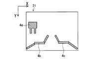
- FIG. 11 is a diagram showing an example of the region of interest detected in the reference image 21 (FIG. 3).
- the attention areas 4 a, 4 b, and 4 c are detected by the attention area detection processing performed by the detection unit 17 ⁇ / b> A to detect the basic graphic area described above.
- the attention area 4a is a basic graphic area corresponding to the image of the standing signboard included in the area 5a (FIG. 3) of the reference image 21, and the attention areas 4b and 4c are the outer edges of the sidewalk image in the reference image 21. This is a basic figure area corresponding to a part. Note that, in the reference image 21 of FIG. 11, only the region of interest detected for easy understanding is shown.
- the detection unit 17A based on the set operation mode, for example, based on feature point information such as a refraction point detected from point sequence information constituting the outline of the reference image 21, at least Each closed figure such as a triangle or a quadrangle composed of three basic figures is detected, and a rectangular area including each detected closed figure at a ratio equal to or higher than a predetermined reference value is detected as a target area in the reference image 21. It is also possible to perform processing.
- FIG. 27 is a diagram for explaining an operation flow S130b in which the detection unit 17A detects a near-far conflict region described later as a region of interest.
- the operation flow S130b of FIG. 27 is started when the operation mode for detecting the near and far conflict area as the attention area is set.
- the detection unit 17A sets one or more block areas such as a rectangular area in the original distance image 31 (step S141 in FIG. 27).
- FIG. 12 is a diagram illustrating an example of the block area 6 a set in the original distance image 31.
- the block area 6a is a rectangular area such as a 320 ⁇ 320 pixel size, for example.
- FIG. 13 is a histogram 64 showing an example of a statistical distribution state of the distance information in the block area 6a (FIG. 12).
- the horizontal axis of the histogram 64 shows the divided parallax (distance information) as a variable.
- the vertical axis indicates the frequency (number) of pixels belonging to each section of the separated parallax.
- the block area 6a includes a standing signboard and the stereo camera 300 side with respect to the standing signboard, or The trees that are located on the opposite side are photographed at the same time.
- the distribution of the distance information of each pixel in the block region 6a is expressed as a histogram with parallax (distance information) as a variable, the histogram has discrete frequency distribution peaks as exemplified by the histogram 64. (Discontinuity) and the distribution width of the distance information is widened.
- the object expressed as a histogram is usually a region in which foreground subjects and distant subjects whose distances from the stereo camera 300 are discrete from each other are mixed like the region 5a of the reference image 21.
- this region is also referred to as “far / far conflict region”, and the statistical distribution state of distance information in the near / far conflict region is also referred to as “far / far conflict state”.
- the detection unit 17A detects a near and far conflict region detected based on a statistical distribution state of the distance information of the original distance image 31 as a region of interest.
- the distance competing region usually has a wider distribution range of distance information and a discrete distribution state of the distance information than regions other than the perspective competing region. Therefore, when the reduction process for reducing the variation of the first distance information 27 (original distance image 31) is performed on the original distance image 31, the perspective competitive area is compared with the area other than the perspective competitive area. Thus, variation in distance information is likely to occur at the boundary portion along the second direction. That is, the perspective conflict region is a region that is more likely to cause image distortion in the pseudo image 24 than regions other than the perspective conflict region.
- the width w1 is the top 5% of the total number of pixels in the block region 6a when all the pixels belonging to the block region 6a are counted in order from the one with the largest parallax value. This is the distribution width of the parallax (distance information) corresponding to each pixel other than the pixels falling in the lower 5%. It should be noted that the removal of pixels that fall within the upper 5% and lower 5% is caused by an error in the search for corresponding points between the base image 21 and the reference image 22, and the acquired distance information is significantly different from the actual distance information. This is done to remove the pixels that are present.
- the widths w2 and w3 in the histogram 64 are distribution widths of parallax (distance information) corresponding to continuous sections among the parallax sections having a frequency lower than a predetermined threshold th1 for the frequency.
- the width w2 or w3 is large, the parallax distribution of the block region 6a is discrete.
- the detection unit 17A uses at least one of the width w1 and the width w2 (w3) in the histogram 64 as an index that expresses the statistical distribution state of each distance information for the block area of the original distance image 31. Get as a value. Moreover, even if the detection unit 17A adopts, for example, the standard deviation of each distance information for the block area of the original distance image 31 as an index value expressing the statistical distribution state of the distance information, the block area Since it can be determined whether or not it is a far and near competitive region, the usefulness of the present invention is not impaired.
- the detection unit 17A uses a predetermined standard that defines the degree of distance conflict between the acquired statistical distribution states of each distance information. It is determined whether or not it is satisfied (step S144 in FIG. 27). Specifically, for the selected block region, for example, the detection unit 17A acquires the above-described width w1 as an index value that represents the statistical distribution state of each distance information, and the width w1 is equal to or greater than a predetermined reference value. That is, it is determined whether or not the statistical distribution state of each piece of distance information for the block region satisfies a predetermined criterion that defines the degree of perspective conflict.
- the detection unit 17A has the block region in the perspective conflict state. It is detected as a region of interest (step S145).
- the detection unit 17A confirms whether or not the determination in step S145 has been completed for all block regions set in the original distance image 31 (step S146). As a result of the confirmation, if the determination in step S145 has not been completed for all the block areas, the detection unit 17A returns the process to step S142. As a result of the confirmation in step S146, the detection unit 17A If the determination of S145 is completed, the detection unit 17A ends the process of detecting the region of interest in the original distance image 31. As described above, the detection unit 17A detects a region of interest in the original distance image 31 using the statistical distribution state of each piece of distance information in the original distance image 31 as a determination condition.
- FIG. 14 is a diagram showing a region of interest 4d as an example of the region of interest detected in the original distance image 31.
- the attention area 4d is detected by the detection unit 17A that employs the above-described width w1 as a statistical distribution state of each distance information for the selected block area.
- the attention area 4d includes a block area where the distance information gently changes and the distribution width of the distance information satisfies a predetermined criterion, in addition to the block area which is the near and far conflict area.
- the detection unit 17A uses the above-described width w2 (w3), the standard deviation of each distance information for the block area, as the statistical distribution state of each distance information for the selected block area, Alternatively, if a combination of these, or a combination of the combination and the width w1 is employed, the size of the region of interest detected in the original distance image 31 becomes smaller than the region of interest 4d (FIG. 14), and the near and far competition state occurs. The detection accuracy of a certain region of interest can be improved.
- FIG. 15 is a diagram showing a region of interest 1a as another example of the region of interest.
- the detection unit 17A displays an overlapping area between the attention areas 4a to 4c (FIG. 11) detected in the reference image 21 (FIG. 11) and the attention area 4d detected in the original distance image 31 (FIG. 14). It is detected as the region of interest 1a in the space 57 (FIG. 15).
- the non-target area 3 a is an area other than the target area 1 a in the image space 57.
- the image space 57 is an image space corresponding to the derived distance image 32 (second distance information 28).
- the image space 57 corresponds to the standard image 21 (FIG. 3) and the reference image 22 (FIG. 4), and also corresponds to the original distance image 31 (FIG. 7).
- the reference image A region that is both a region and a perspective conflict region can be detected as the region of interest 1a.
- the attention area is determined based on one of the attention areas 4a to 4c and the attention area 4d. Even if a detection method is employed, the usefulness of the present invention is not impaired. In addition, according to this method, it is possible to perform the target area detection process at a higher speed.
- Region of interest detection processing based on correlation values in corresponding point search The detection unit 17A is acquired for each of the first distance information 27 when the corresponding point search process is performed between the reference image 21 and the reference image 22 and the first distance information 27 is acquired. Detection processing for detecting a region of interest in the image space corresponding to the original distance image 31 is performed according to the set operation mode using each correlation value as a determination condition.
- the region where the correlation values corresponding to the first distance information 27 are low is a region where the variation of the first distance information 27 is larger than the region where the correlation values are high. Therefore, when the reduction process for reducing the variation of the first distance information 27 (original distance image 31) is performed on the original distance image 31, the correlations corresponding to the first distance information 27. In a region having a low value, variation in distance information is likely to occur in the boundary portion along the second direction, compared to a region having a high correlation value. That is, the region where the correlation values corresponding to the first distance information 27 are low may cause image distortion in the pseudo image 24 than the region where the correlation values corresponding to the first distance information 27 are high. This is a strong area.
- the region information 2a (FIG. 2) regarding the region of interest detected by the detection unit 17A is supplied to the first generation unit 14A. Accordingly, the first generation unit 14A described later can detect the region of interest in the original distance image 31 by referring to the region information 2a.
- the operation mode of the first generation unit 14A is set to the operation mode that uses the region information 2a
- the first generation unit 14A performs at least the region of interest in the image space of the original distance image 31.
- the reduction intensity that reduces the variation of the first distance information 27 in the second direction in the region of interest is stronger than the reduction intensity that reduces the variation of the first distance information 27 in the first direction in the region of interest.
- the second distance information 28 is generated.
- the first generation unit 14 ⁇ / b> A performs a variation reduction process in which the variation reduction strengths of the first distance information 27 in the first direction and the second direction are different from each other, for example, in the original distance image 31.
- FIG. 16 is a diagram showing an example of a plurality of regions of interest detected in the image space 57.
- three regions of interest 1a to 1c are included in the non-region of interest 3b and detected.
- the attention areas 1a to 1c are given quantitative determination results about the possibility of image distortion in the image space of the pseudo image 24 corresponding to the attention areas 1a to 1c, respectively.
- the detection unit 17A detects the region of interest in the reference image 21 shown in FIG. 26, the reference value of the basic figure length in step S133 and the contour detected in the reference image 21 in step S136.
- step S133, S136 in FIG. 26 or step S144 in FIG. 27 is increased, the reliability of the region of interest in the image space 57 detected by the detection unit 17A is increased.
- the detection unit 17A detects the region of interest detected in the image space 57, and the region of interest is the image of the pseudo image 24.
- a quantitative determination result (reliability) about the possibility of image distortion in space a value corresponding to the above-described reference value in steps S133 and S136 in FIG. 26 or step S144 in FIG. 27 is acquired.
- the detection unit 17A associates the acquired quantitative determination result with the detected region of interest. That is, the detection unit 17A detects a region of interest using a determination rule that assigns a quantitative determination result to the detected region of interest as to whether the region of interest may cause image distortion in the image space of the pseudo image 24. It can also be used as the determination condition.
- the quantitative determination result given to the detected region of interest is supplied to the first generator 14A together with the region information 2a regarding the region of interest.
- the first generation unit 14A When the first generation unit 14A is set to the operation mode using the region information 2a, the first generation unit 14A further refers to the result of the quantitative determination regarding the possibility of causing the image distortion described above.
- the mode for example, the first generation unit 14A causes the image of the pseudo image 24 to be distorted based on the quantitative determination result regarding the possibility of distorting the image.
- the variation in the first distance information 27 in the second direction in the region of interest is reduced. Strengthen.
- the first generation unit 14A prevents an excessive decrease in the distance information about the region of interest, and in the region of the pseudo image corresponding to the region of interest. Image distortion can be suppressed.
- Reduction process A When the operation mode of the first generation unit 14A (FIG. 2) is not set to the operation mode using the region information 2a (FIG. 2), the first generation unit 14A displays the image space of the original distance image 31 in the image space. Intensity to reduce variation in the first distance information 27 in the second direction (Y-axis direction in FIG. 7) across the first direction (X-axis direction in FIG. 7) in the original distance image 31 for the entire area. By performing the reduction process A for reducing the variation of the first distance information 27 so as to be stronger than the intensity for reducing the variation of the first distance information 27 in the first direction in the original distance image 31, 2 each distance information 28 (FIG. 2) is generated.
- the reduction process A when the reduction process A is performed, in the second distance information 28 generated by the first generation unit 14A, the variation in the distance information regarding the second direction crossing the first direction is related to the first direction. It becomes smaller than the variation of each distance information. Then, the pseudo image 24 (FIG. 2) is generated by the second generation unit 15A described later based on the generated second distance information 28. Therefore, when the first generation unit 14A performs the reduction process A, the first generation unit 14A performs the general process described above with reference to the averaging filter 55, FIG. 9, and FIG. 10 illustrated in FIG. Smoothing process, that is, a general reduction process for reducing variations in the first distance information 27 so that the smoothing intensities in the first direction and the second direction are equal to each other. Compared with the case where the distance information 28 is generated, distortion such as curvature of the image generated in the pseudo image 24 can be reduced.
- Reduction process B When the operation mode of the first generation unit 14A is set to the operation mode using the region information 2a, the first generation unit 14A stores at least the region information 2a in the image space of the original distance image 31.
- the second distance information 28 is generated by performing the reduction process B for reducing the variation of the first distance information 27 so as to be stronger than the intensity for reducing the variation of the 27.
- the second distance information 28 generated by the first generation unit 14A When the reduction process B is performed, in the second distance information 28 generated by the first generation unit 14A, at least the attention area detected based on the area information 2a is crossed in the first direction. Variations in the distance information regarding the two directions are smaller than variations in the distance information regarding the first direction. Then, the pseudo image 24 (FIG. 2) is generated by the second generation unit 15A described later based on the generated second distance information 28.
- the region of interest in the original distance image 31 is a region that is more likely to cause image distortion in the corresponding region of the pseudo image 24 than the non-region of interest other than the region of interest. Therefore, when the first generation unit 14A performs the reduction process B, the first generation unit 14A has a general smoothing strength equal in the first direction and the second direction described above in the description of the reduction process A. Compared with the case where the reduction process is performed, distortion such as curvature of an image generated in the pseudo image 24 generated based on each second distance information 28 can be reduced.
- the distortion of the image in the region of the pseudo image corresponding to the region of interest is prevented while preventing an excessive decrease in the distance information about the region other than the region of interest. Can be suppressed.
- the first generation unit 14A generally has the same smoothing strength in the first direction and the second direction. Compared with the case where the reduction process is performed, distortion such as the curvature of the image generated in the pseudo image 24 generated based on the second distance information 28 can be reduced, which impairs the usefulness of the present invention. is not.
- the operation flow S100A illustrated in FIG. 25 is an operation flow when the operation mode of the first generation unit 14A is set to an operation mode corresponding to the reduction process B.
- Processing content of reduction processing B (A): When the first distance information 27 (FIG. 2) and the region information 2a (FIG. 2) about the region of interest 1a (FIG. 15) are respectively supplied from the second acquisition unit 13 and the detection unit 17A, the first information
- the generation unit 14A stores smoothing information 53a and smoothing information 53b (FIG. 2) corresponding to the first and second smoothing filters respectively applied to the non-target region 3a and the target region 1a.
- the first and second smoothing filters are acquired by acquiring from the unit 48 (FIG. 2) (step S140 in FIG. 25).
- the smoothing information 53a and 53b are information for specifying the first and second smoothing filters respectively applied to the non-target region 3a and the target region 1a.
- the smoothing information 53a and 53b are stored in advance in the smoothing information storage unit 48 (FIGS. 1 and 2).
- the smoothing information 53a for example, the type of the smoothing filter and the smoothing strength of the smoothing filter are employed.
- the smoothing information 53a includes a variable for designating a filter type called a median filter, A variable that specifies the smoothing strength is adopted, and a variable that designates a filter type called an averaging filter and a variable that designates the smoothing strength of the filter are adopted as the smoothing information 53b.
- FIGS. 19 to 21 are diagrams showing examples of the averaging filters 56a, 56b, and 56c according to the embodiment.
- FIG. 22 is a diagram for explaining an example of processing for reducing variation in the original distance image 31 (first distance information 27) according to the embodiment.
- the averaging filter 55 shown in FIG. 8 is adopted as the first smoothing filter
- the averaging filter 56a shown in FIG. 19 is mainly adopted as the second smoothing filter.
- the operation of the 1 generator 14A will be described.
- the first generation unit 14A acquires, for example, information specifying the type of the averaging filter 55 and the parameter K having a value 94 as the smoothing information 53a for the averaging filter 55. Further, the first generation unit 14A acquires, for example, information specifying the type of the averaging filter 56a and the parameters K1 and K2 having values 189 and 64 as the smoothing information 53b for the averaging filter 56a. When the first generation unit 14A performs the reduction process A, the first generation unit 14A acquires only the smoothing information 53b corresponding to the averaging filter 56a.
- the first generation unit 14A uses the smoothing information programs corresponding to the respective smoothing processes using the first and second smoothing filters as the smoothing information 53a and the smoothing information 53b, respectively.
- the configuration may be such that each smoothing process using each of the first and second smoothing filters is performed by executing each of the acquired smoothing process programs acquired from 48.
- the reduction intensity of variation of the first distance information 27 in the second direction (Y-axis direction) is about three times the reduction intensity of variation of the first distance information 27 in the first direction (X-axis direction). It is.
- the intensity ratio is not limited to 3 times. For example, even if an arbitrary value of 1.2 times or more is adopted, the usefulness of the present invention is not impaired.
- the averaging filter 56b (FIG. 20) is employed instead of the averaging filter 56a, the usefulness of the present invention is not impaired.
- the value 94 is adopted as the parameter K.
- the first generation unit 14A employs the averaging filter 56a, the first generation unit 14A includes the first distance information only in the second direction among the first direction and the second direction in the original distance image 31.
- the reduction process B (A) is performed by reducing the 27 variations. That is, even if the averaging filter 56b is applied, the reduction intensity of the variation in the distance information regarding the second direction can be made larger than the reduction intensity of the variation of the distance information regarding the first direction.
- the averaging filter 56c (FIG. 21) is employed instead of the averaging filter 56a, the usefulness of the present invention is not impaired.
- a value 189, a value 94, and a value 95 are employed as the parameters K1, K2, and K3, respectively.
- the value 3 is adopted as the value of each matrix element in the central portion in the X-axis direction
- the value 1 is adopted as the value of each matrix element in both ends in the X-axis direction.
- the averaging filter 56c In the averaging filter 56c, the number of elements in the X-axis and Y-axis directions is the same, but the values of the elements are different between the center and both ends, so the averaging filter 56c, which is a weighted averaging filter, Even if it is applied, the reduction intensity of the variation of each distance information regarding the second direction can be made larger than the reduction intensity of the variation of each distance information regarding the first direction.
- the first generation unit 14A has a vertically long block region in which the length in the second direction (Y-axis direction) is longer than the length in the first direction (X-axis direction).
- 58 is set in the original distance image 31, and the average value of each distance information corresponding to the block area 58 among the first distance information 27 is acquired, and the second distance information 28 is obtained based on the acquired average value.
- the process of acquiring the value of each distance information corresponding to the block area 58 is performed while moving the block area 58 stepwise in the first direction and the second direction as shown in FIG. Even if the reduction process B (A) is performed, the usefulness of the present invention is not impaired.
- the size of the block region 58 for example, 4 is employed as the number of pixels in the first direction (X-axis direction), and 8 is employed as the number of pixels in the second direction (Y-axis direction).
- the first generation unit 14A is an operation mode in which an operation mode corresponding to the reduction process B is set, and an operation mode that refers to a quantitative determination result regarding the possibility of causing distortion of the image generated by the detection unit 17A.
- the smoothing strength of the second smoothing filter is adjusted (step S150 in FIG. 25). The adjustment is performed, for example, when it is estimated that the region of interest 1a is likely to cause image distortion of the pseudo image 24 based on the result of quantitative determination regarding the possibility of image distortion.
- the reduction intensity for reducing the variation of the first distance information 27 in the second direction in the region of interest 1a is increased.
- the first generation unit 14A uses the reduction intensity of the variation of the first distance information 27 in the second direction for the region of interest 1a as a quantitative measure for the possibility of causing distortion supplied from the detection unit 17A. Change according to the judgment result.
- the ratio of the reduction intensity of the variation of the first distance information 27 in the second direction to the reduction intensity of the variation of the first distance information 27 in the first direction is: For example, in the range of 1.2 or more, adjustment is made according to the result of quantitative determination regarding the possibility of causing distortion.
- the first generation unit 14A prevents the distance information about the region of interest from being excessively reduced, and the pseudo generated by the second generation unit 15A. In the image 24, distortion of the image in the region corresponding to the region of interest can be suppressed.
- FIG. 17 is a diagram showing an example of the derived distance image 32 (second distance information 28).
- the first generation unit 14A performs a smoothing process using the acquired smoothing filter, whereby the original distance image 31 (first each image The pixel value of each pixel of the distance information 27) is smoothed to generate the derived distance image 32 (second distance information 28) (step S160 in FIG. 25). That is, the first generation unit 14 ⁇ / b> A has a strength that reduces the variation of the first distance information 27 in the second direction across the first direction in the original distance image 31. A reduction process for reducing the variation of the first distance information 27 is performed so as to be stronger than the strength for reducing the variation of the distance information 27.
- the reduction process B (A) is performed. Even if it is performed, the usefulness of the present invention is not impaired.
- the second direction is orthogonal to the first direction, and the second direction is, for example, in the range of ⁇ 30 ° to + 30 ° with respect to the orthogonal direction. Even if a smoothing filter corresponding to such a smoothing process is employed, the usefulness of the present invention is not impaired.
- FIG. 18 is a diagram illustrating an example of the pseudo image 24 (FIG. 2) in which image distortion is suppressed.
- the second generator 15A generates the pseudo image 24 (FIG. 18) based on the reference image 21 (FIG. 3) and the second distance information 28 (derived distance image 32) (FIG. 17) (FIG. 25).
- Step S170 That is, the second generation unit 15 ⁇ / b> A generates a pseudo image 24 that forms a stereoscopic image by combination with the reference image 21 based on the reference image 21 and the second distance information 28.
- the second generation unit 15A employs the basic method related to generation of the pseudo image described above with reference to FIGS.
- the pseudo image 24 corresponding to the photographing of the subject from the virtual viewpoint is acquired by deforming the reference image 21 based on the distance information (parallax) of the supplied derived distance image 32 (second distance information 28). .
- the region 5c in the pseudo image 24 is a region corresponding to each of the region 5a in the reference image 21 (FIG. 3) and the region 5b in the pseudo image 25 (FIG. 10) in which image distortion is not corrected.
- the spatial distortion of the image curved convexly in the ⁇ X direction in the region 5b is suppressed.
- the image processing apparatus 200A performs the first distances in the second direction (Y-axis direction in FIG. 7) that crosses the first direction (X-axis direction in FIG. 7) in the original distance image 31 (FIG. 7).
- the variation of the first distance information 27 is reduced so that the strength of reducing the variation of the information 27 is stronger than the strength of reducing the variation of the first distance information 27 in the first direction in the original distance image 31.
- the second distance information 28 is generated by performing the reduction process.
- the second cause of variation in the distance information regarding the second direction crossing the first direction that is, the main cause of the geometric distortion of the pseudo image. Variations in the distance information regarding the direction are smaller than variations in the distance information regarding the first direction. Since the image processing apparatus 200A generates the pseudo image 24 based on the generated second distance information 28, distortion such as curvature of the image generated in the pseudo image 24 can be reduced. That is, the image processing apparatus 200A can reduce image distortion that occurs in the pseudo image.
- the base line length direction of the base camera 61 and the reference camera 62 is the vertical direction, but the base line length direction may be the vertical direction or any other direction. Good. Further, the shooting magnifications of the base camera 61 and the reference camera 62 may not be the same.
- the pseudo image 24 is obtained by changing the handling as the base camera and the reference camera between the cameras. The pseudo image 24 may be generated from each image captured by the camera.
- Image processing system 200A Image processing apparatus 300 Stereo camera 1a, 1b, 1c Region of interest 2a Region information 3a, 3b Non-region of interest 4a-4d Region of interest 6a Block region 9a, 9b Parallax 21, 21a Reference image 22, 22a Reference image 23a , 23b Partial image 24 Pseudo image 25 Pseudo image 27 First distance information 28 Second distance information 29 Each distance information 31 Original distance image 32 Derived distance image 33 Distance image 53a, 53b Smoothing information 55, 56a to 56c Averaging filter 57 Image space 61 Base camera 62 Reference camera w1, w2, w3 width th1 threshold
Landscapes
- Engineering & Computer Science (AREA)
- Physics & Mathematics (AREA)
- General Physics & Mathematics (AREA)
- Theoretical Computer Science (AREA)
- Multimedia (AREA)
- Signal Processing (AREA)
- Testing, Inspecting, Measuring Of Stereoscopic Televisions And Televisions (AREA)
- Image Processing (AREA)
Abstract
Description
<画像処理システム100Aについて:>
図1は、実施形態に係る画像処理システム100Aの主な構成の1例を示すブロック図である。図1に示されるように、画像処理システム100Aは、ステレオカメラ300と画像処理装置200Aとを主に備えて構成されている。画像処理システム100Aでは、ステレオカメラ300が撮影した基準画像21(図1、図2)および参照画像22(図1、図2)を画像処理装置200Aが取得し、画像処理装置200Aが基準画像21および参照画像22を処理することによって、基準画像21が撮影された第1の視点とは別の仮想視点からの被写体の撮影に対応した疑似画像24(図2)、すなわち第1の視点とは別の仮想視点から撮影した被写体の画像に相当する疑似画像24を生成する。疑似画像24は、基準画像21との組み合わせによって立体視可能な立体画像を構成する。
図1に示されるように、ステレオカメラ300は、基準カメラ61と参照カメラ62とを主に備えて構成されている。また、基準カメラ61および参照カメラ62は、それぞれ、不図示の撮影光学系および制御処理回路を主に備えて構成されている。また、基準カメラ61と参照カメラ62とは、垂直方向に所定の基線長を隔てて設けられており、撮影光学系に入射した被写体からの光線情報を制御処理回路等で同期して処理することによって、被写体のステレオ画像を構成する、例えば、3456×2592画素サイズなどの所定サイズのデジタル画像である基準画像21(図1、図3)および参照画像22(図1、図4)を生成する。また、ステレオカメラ300の各種動作は、画像処理装置200Aから入出力部41および通信回線DLを介して供給される制御信号に基づいて制御される。通信回線DLは、有線の回線であっても無線の回線であっても良い。
図1に示されるように、画像処理装置200Aは、CPU11A、入出力部41、操作部42、表示部43、ROM44、RAM45および記憶装置46を主に備えて構成されており、例えば、汎用のコンピュータでプログラムを実行することなどによって実現される。
図2は、実施形態に係る画像処理装置200Aの主な機能構成の1例を示すブロック図である。図3および図4は、実施形態に係るステレオカメラ300の基準カメラ61および参照カメラ62が、それぞれ被写体を撮影した基準画像21および参照画像22の1例をそれぞれ示す図である。また、図25~図27は、実施形態に係る画像処理装置200Aの動作フローをそれぞれ例示する図である。以下では、画像処理装置200Aが、基準画像21と参照画像22とに基づいて、基準画像21が撮影された第1の視点とは別の仮想視点からの被写体の撮影に対応した疑似画像24(図18)、すなわち基準画像21との組み合わせによって立体視可能な立体画像を構成する疑似画像24を生成する場合を例に、画像処理装置200Aの各機能部の動作について図25~図27の動作フローを適宜参照しつつ説明する。
被写体が第1の視点から撮影された基準画像21と参照画像22とが入出力部41に供給されると、第1取得部12(図2)は、入出力部41を介して基準画像21を取得するとともに(図25の動作フローS100AにおけるステップS110)、参照画像22を取得する。
図7は、第2取得部13(図2)が取得する原距離画像31(第1の各距離情報27)の1例を示す図である。基準画像21および参照画像22が第2取得部13に供給されると、第2取得部13は、基準画像21と参照画像22とを対象として、相関演算法などを用いた対応点探索処理を行うことによって、基準画像21の各注目画素に対応する参照画像22の各対応画素を特定する。そして、第2取得部13は、相互に対応する注目画素と対応画素とについて、基準画像21の画像座標系における該注目画素の画素座標と、参照画像22の画像座標系における該対応画素の画素座標との差(本願において、「視差」とも称する)を求める処理を、基準画像21の各注目画素に対して行う。
図5は、基準画像21aと参照画像22aとにおける視差の1例を説明するための図である。なお、基準画像21aは、基準カメラ61によって撮影された被写体の基準画像21(図2)の1例であり、参照画像22aは、基準カメラ61に対して垂直方向(図5の+Y方向)に所定の基線長を隔てて設けられた参照カメラ62によって撮影された該被写体の参照画像22(図2)の1例である。図5おいては、基準画像21aと参照画像22aとは、視差の把握を容易にするため該両画像の上端(下端)のY座標が等しくなるように水平方向(図5のX軸方向)に並べて表示されている。

次に、基準画像21との組み合わせによって立体画像を構成する疑似画像24を、基準画像21の各画素に対応した各視差、または各距離などの各距離情報に基づいて生成する手法について説明する。互いに立体画像を構成する基準画像21と疑似画像24とが同一の画像空間に立体視可能な配置関係に配置された場合には、互いに被写体上の同一の点に対応する基準画像21の注目画素と疑似画像24の対応画素との該画像空間における位置ずれの方向、すなわち視差の方向は、同一の方向となる。本願においては、該同一の方向を「第1方向」とも称する。なお、基準画像21とそれぞれ立体画像を構成する複数の疑似画像が生成され、該複数の疑似画像のうち2つの疑似画像が互いに立体視可能な配置関係に配置されたとしても、該2つの疑似画像間において被写体上の同一の点にそれぞれ対応した画素間の方向は、該第1方向となる。
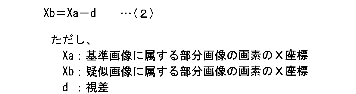
ところで、ステレオカメラ300においては、通常、基準画像21の各画素にそれぞれ対応した参照画像22の各画素を特定する対応付けなどにおいて誤差が発生する。また、アクティブ測距方式の三次元測定機においても基準カメラ61のカメラ視線と、被写体に投影される検出光との交差に関する位置情報、時間情報などについての誤差が発生する。このため、図7に例示された第1の各距離情報27(原距離画像31)には、通常、ランダムノイズ状の測定のばらつきなどの各種の測定誤差が含まれる。
次に、距離情報などのばらつきを低減させる一般的な平滑化処理ついて説明する。原距離画像31などの画像データの平滑化処理として、一般的に、例えば、平均化フィルタ、メディアンフィルタ、またはガウシアンフィルタなどの各種の平滑化フィルタを採用した平滑化処理が行われる。該平滑化処理においては、平滑化対象の画像の各画素に対して、平滑化の強度(「平滑化強度」とも称する)が一定である平滑化フィルタが適用される。なお、平滑化フィルタの平滑化強度は、例えば、フィルタのサイズを変更することなどによって変更され得る。
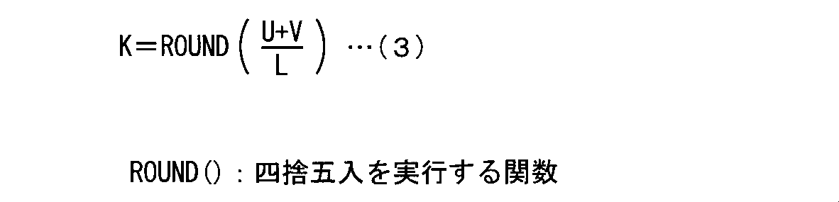
また、図10は、図9に示された距離画像33(各距離情報29)に対して上述した疑似画像生成の基本手法が適用されることにより生成された疑似画像25を示す図である。疑似画像25の領域5bには、図3の基準画像21の領域5aの画像、すなわち直線などの基本図形要素を多く有して構成された人工物(立て看板)の画像に対応した画像が生成されている。
上述したように、原距離画像31における第1の各距離情報27の変動が疑似画像の形状的な歪みに与える影響には異方性があり、最終的に立体画像における形状的な歪みとなる疑似画像の形状的な歪みの主たる原因は、原距離画像31における第1の各距離情報27の変動方向(ばらつき方向)が第2方向に沿っていることである。
検出部17A(図2)は、予め設定された判定条件に基づいて、歪みが抑制された疑似画像24の生成に用いられる第2の各距離情報28(派生距離画像32)(図2、図17)に対応した画像空間、すなわち基準画像21および原距離画像31に対応した画像空間を、疑似画像24における画像の歪みを生ずる可能性が強い領域(「着目領域」とも称する)と、着目領域よりも疑似画像24における画像の歪みを生ずる可能性が弱い非着目領域とに分類して検出する。すなわち、検出部17Aは、所定の判定条件に基づいて、原距離画像31(図2)に対応した画像空間のうち疑似画像24における画像の歪みを生ずる可能性がある着目領域を検出する(図25のステップS130)。なお、本願においては、第2の各距離情報28、すなわち第1の各距離情報27のばらつきを低減する処理によって第1の各距離情報27から派生する第2の各距離情報28が、基準画像21の画素配列に応じて配列された各距離情報を「派生距離画像」とも称する。
図26は、検出部17Aが、後述する基本図形領域を着目領域として検出する動作フローS130aを説明する図である。ステップS130(図25)の処理が開始されると、基本図形領域を着目領域として検出する動作モードが設定されている場合には、図26の動作フローS130aが開始される。検出部17Aは、例えば、Cannyアルゴリズムなどを使用した画像処理を行うことによって、基準画像21(図3)に存在する輪郭(エッジ)を検出する(ステップS131)。また輪郭検出の手法としては、例えば、ソーベルフィルタなどの微分フィルタを用いた画像処理なども採用され得る。
図27は、検出部17Aが、後述する遠近競合領域を着目領域として検出する動作フローS130bを説明する図である。ステップS130の処理が開始されると、遠近競合領域を着目領域として検出する動作モードが設定されている場合には、図27の動作フローS130bが開始される。先ず、検出部17Aは、原距離画像31に1以上の、例えば、矩形領域などのブロック領域を設定する(図27のステップS141)。図12は、原距離画像31に設定されたブロック領域6aの1例を示す図である。ブロック領域6aは、例えば、320×320画素サイズなど矩形領域である。
検出部17Aは、基準画像21と参照画像22との間で対応点探索処理が行われて第1の各距離情報27が取得される際に第1の各距離情報27に対してそれぞれ取得される各相関値を判定条件として、原距離画像31に対応した画像空間における着目領域を検出する検出処理を、設定された動作モードに応じて行う。
図16は、画像空間57において検出された複数の着目領域の1例を示す図であり、画像空間57では3つの着目領域1a~1cが非着目領域3bに内包されて検出されている。そして、着目領域1a~1cには、着目領域1a~1cにそれぞれ対応する疑似画像24の画像空間において画像の歪みが生ずる可能性についての定量的な判定結果がそれぞれ付与されている。
低減処理A:
第1生成部14A(図2)の動作モードが、領域情報2a(図2)を使用する動作モードに設定されていない場合には、第1生成部14Aは、原距離画像31の画像空間の全域を対象として、原距離画像31における第1方向(図7のX軸方向)を横切る第2の方向(図7のY軸方向)について第1の各距離情報27のばらつきを低減させる強度が、原距離画像31における第1方向について第1の各距離情報27のばらつきを低減させる強度よりも強くなるように第1の各距離情報27のばらつきを低減させる低減処理Aを行うことによって、第2の各距離情報28(図2)を生成する。
また、第1生成部14Aの動作モードが、領域情報2aを使用する動作モードに設定されている場合には、第1生成部14Aは、原距離画像31の画像空間のうち少なくとも領域情報2aに基づいて検出される着目領域に対して、該着目領域における第2方向についての第1の各距離情報27のばらつきを低減させる強度が、該着目領域における第1方向についての第1の各距離情報27のばらつきを低減させる強度よりも強くなるように第1の各距離情報27のばらつきを低減させる低減処理Bを行うことによって、第2の各距離情報28を生成する。
第2取得部13と検出部17Aとから、第1の各距離情報27(図2)と着目領域1a(図15)についての領域情報2a(図2)とがそれぞれ供給されると、第1生成部14Aは、非着目領域3aおよび着目領域1aに対してそれぞれ適用される第1および第2平滑化フィルタにそれぞれ対応した平滑化情報53aおよび平滑化情報53b(図2)を平滑化情報格納部48(図2)から取得することによって、第1および第2平滑化フィルタをそれぞれ取得する(図25のステップS140)。なお、平滑化情報53aおよび53bは、非着目領域3aおよび着目領域1aにそれぞれ適用される第1および第2平滑化フィルタをそれぞれ特定する情報である。平滑化情報53aおよび53bは、予め、平滑化情報格納部48(図1、図2)に格納されている。
図18は、画像の歪みが抑制された疑似画像24(図2)の1例を示す図である。第2生成部15Aは、基準画像21(図3)と第2の各距離情報28(派生距離画像32)(図17)とに基づいて疑似画像24(図18)を生成する(図25のステップS170)。すなわち、第2生成部15Aは、基準画像21との組み合わせによって立体画像を構成する疑似画像24を、基準画像21と第2の各距離情報28とに基づいて生成する。具体的には、第2生成部15Aは、例えば、図23、図24、および(2)式などを参照しつつ上述した疑似画像の生成に係る基本手法を採用し、第1生成部14Aから供給される派生距離画像32(第2の各距離情報28)の距離情報(視差)に基づいて基準画像21を変形させることなどによって仮想視点からの被写体の撮影に対応した疑似画像24を取得する。
以上、本発明の実施の形態について説明してきたが、本発明は上記実施の形態に限定されるものではなく様々な変形が可能である。
200A 画像処理装置
300 ステレオカメラ
1a,1b,1c 着目領域
2a 領域情報
3a,3b 非着目領域
4a~4d 着目領域
6a ブロック領域
9a,9b 視差
21,21a 基準画像
22,22a 参照画像
23a,23b 部分画像
24 疑似画像
25 疑似画像
27 第1の各距離情報
28 第2の各距離情報
29 各距離情報
31 原距離画像
32 派生距離画像
33 距離画像
53a,53b 平滑化情報
55,56a~56c 平均化フィルタ
57 画像空間
61 基準カメラ
62 参照カメラ
w1,w2,w3 幅
th1 閾値
Claims (13)
- 被写体が撮影された基準画像を取得する第1の取得部と、
前記被写体の各点のうち前記基準画像の各画素にそれぞれ対応した各点について、予め設定された原点位置からの距離情報をそれぞれ表現した第1の各距離情報を取得する第2の取得部と、
前記第1の各距離情報のばらつきを低減させる低減処理によって第2の各距離情報を生成する第1の生成部と、
前記基準画像との組み合わせによって立体画像を構成する疑似画像を、前記基準画像と前記第2の各距離情報とに基づいて生成する第2の生成部と、
を備え、
前記基準画像と前記疑似画像とが同一の画像空間に立体視可能に配置されたときに、互いに前記被写体上の同一の点に対応する前記基準画像の画素と前記疑似画像の画素との該画像空間における位置ずれの方向によって前記基準画像に対する第1の方向を定義するとともに、前記基準画像の画素配列に対応した前記第1の各距離情報の配列によって原距離画像を定義したとき、
前記第1の生成部は、
前記原距離画像における前記第1の方向を横切る第2の方向について前記第1の各距離情報のばらつきを低減させる強度が、前記原距離画像における前記第1の方向について前記第1の各距離情報のばらつきを低減させる強度よりも強くなるように前記低減処理を行う画像処理装置。 - 請求項1に記載された画像処理装置であって、
前記第1の生成部が、
前記第1の方向と、前記第2の方向とのそれぞれの方向についての平滑化強度が互いに異なる平滑化フィルタ処理を行うことによって前記低減処理を行う画像処理装置。 - 請求項1に記載された画像処理装置であって、
前記第1の生成部が、
前記第1の方向についての長さよりも前記第2の方向についての長さが長い縦長形状のブロック領域を前記原距離画像に設定して前記第1の各距離情報のうち該ブロック領域に対応した各距離情報の平均値を取得するとともに、取得した平均値に基づいて前記第2の各距離情報のうち該ブロック領域に対応した各距離情報の値を取得する処理を、該ブロック領域を前記原距離画像に対してステップ移動させつつ行うことによって前記低減処理を行う画像処理装置。 - 請求項1から請求項3の何れか1つの請求項に記載された画像処理装置であって、
前記第1の生成部が、
前記原距離画像における前記第1の方向と前記第2の方向とのうち前記第2の方向についてのみ前記第1の各距離情報のばらつきを低減させることによって前記低減処理を行う画像処理装置。 - 請求項1から請求項4のいずれか1つの請求項に記載された画像処理装置であって、
予め設定された判定条件に基づいて、前記原距離画像に対応した画像空間のうち前記疑似画像の歪みを生ずる可能性のある着目領域を検出する検出部を更に備え、
前記第1の生成部が、
前記原距離画像のうち前記着目領域に対応した領域を対象として前記低減処理を行う画像処理装置。 - 請求項5に記載された画像処理装置であって、
前記検出部が、
前記基準画像についての幾何学的条件を前記判定条件として前記着目領域を検出する画像処理装置。 - 請求項6に記載された画像処理装置であって、
予め設定された数式のパラメータに具体的数値を与えることによって座標空間での形状およびサイズが特定される図形を基本図形と呼ぶとき、
前記幾何学的条件が、前記基準画像における輪郭を構成する1種類以上の予め設定された基本図形の割合である画像処理装置。 - 請求項7に記載された画像処理装置であって、
前記1種類以上の予め設定された基本図形が、直線、2次曲線、円弧、楕円弧、および予め設定されたテクスチャのうち少なくとも1つである画像処理装置。 - 請求項5に記載された画像処理装置であって、
前記検出部が、
前記第1の各距離情報の統計的な分布状態を前記判定条件として前記着目領域を検出する画像処理装置。 - 請求項5に記載された画像処理装置であって、
前記第2の取得部が、
前記基準画像が撮影された視点とは異なる視点から前記被写体が撮影された参照画像と、前記基準画像との間での対応点探索処理を行うことによって前記第1の各距離情報を取得するとともに、
前記検出部が、
前記第1の各距離情報についての前記対応点探索処理において取得される各相関値を前記判定条件として前記着目領域を検出する画像処理装置。 - 請求項5から請求項10のいずれか1つの請求項に記載された画像処理装置であって、
前記判定条件は、前記歪みを生ずる可能性について定量的な判定結果を与える判定規則を含み、
前記第1の生成部が、
前記着目領域についての前記第2の方向についての前記ばらつきの低減強度を、前記歪みを生ずる可能性についての前記定量的な判定の結果に応じて変更する画像処理装置。 - 画像処理装置に搭載されたコンピュータにおいて実行されることにより、当該画像処理装置を請求項1から請求項11の何れか1つの請求項に記載の画像処理装置として機能させるプログラム。
- 被写体が撮影された基準画像を取得する第1の取得工程と、
前記被写体の各点のうち前記基準画像の各画素にそれぞれ対応した各点について、予め設定された原点位置からの距離情報をそれぞれ表現した第1の各距離情報を取得する第2の取得工程と、
前記第1の各距離情報のばらつきを低減させる低減処理によって第2の各距離情報を生成する第1の生成工程と、
前記基準画像との組み合わせによって立体画像を構成する疑似画像を、前記基準画像と前記第2の各距離情報とに基づいて生成する第2の生成工程と、
を備え、
前記基準画像と前記疑似画像とが同一の画像空間に立体視可能に配置されたときに、互いに前記被写体上の同一の点に対応する前記基準画像の画素と前記疑似画像の画素との該画像空間における位置ずれの方向によって前記基準画像に対する第1の方向を定義するとともに、前記基準画像の画素配列に対応した前記第1の各距離情報の配列によって原距離画像を定義したとき、
前記第1の生成工程は、
前記原距離画像における前記第1の方向を横切る第2の方向について前記第1の各距離情報のばらつきを低減させる強度が、前記原距離画像における前記第1の方向について前記第1の各距離情報のばらつきを低減させる強度よりも強くなるように前記低減処理を行う画像処理方法。
Priority Applications (2)
| Application Number | Priority Date | Filing Date | Title |
|---|---|---|---|
| JP2012557868A JP5874649B2 (ja) | 2011-02-17 | 2012-01-27 | 画像処理装置、そのプログラム、および画像処理方法 |
| US13/982,670 US9215441B2 (en) | 2011-02-17 | 2012-01-27 | Image processing apparatus, non-transitory computer readable recording medium, and image processing method |
Applications Claiming Priority (2)
| Application Number | Priority Date | Filing Date | Title |
|---|---|---|---|
| JP2011-031998 | 2011-02-17 | ||
| JP2011031998 | 2011-02-17 |
Publications (1)
| Publication Number | Publication Date |
|---|---|
| WO2012111404A1 true WO2012111404A1 (ja) | 2012-08-23 |
Family
ID=46672341
Family Applications (1)
| Application Number | Title | Priority Date | Filing Date |
|---|---|---|---|
| PCT/JP2012/051747 Ceased WO2012111404A1 (ja) | 2011-02-17 | 2012-01-27 | 画像処理装置、そのプログラム、および画像処理方法 |
Country Status (3)
| Country | Link |
|---|---|
| US (1) | US9215441B2 (ja) |
| JP (1) | JP5874649B2 (ja) |
| WO (1) | WO2012111404A1 (ja) |
Families Citing this family (7)
| Publication number | Priority date | Publication date | Assignee | Title |
|---|---|---|---|---|
| EP2677733A3 (en) * | 2012-06-18 | 2015-12-09 | Sony Mobile Communications AB | Array camera imaging system and method |
| JP2014230251A (ja) * | 2013-05-27 | 2014-12-08 | ソニー株式会社 | 画像処理装置、および画像処理方法 |
| RU2017116578A (ru) | 2014-10-14 | 2018-11-15 | Конинклейке Филипс Н.В. | Обработка диспарантности трехмерного изображения |
| WO2019076278A1 (en) * | 2017-10-19 | 2019-04-25 | Zhejiang Dahua Technology Co., Ltd. | METHODS AND DEVICES FOR PROCESSING IMAGES |
| JP7253323B2 (ja) * | 2018-02-14 | 2023-04-06 | オムロン株式会社 | 3次元計測システム及び3次元計測方法 |
| JP6857147B2 (ja) * | 2018-03-15 | 2021-04-14 | 株式会社日立製作所 | 三次元画像処理装置、及び三次元画像処理方法 |
| EP3667617A1 (en) * | 2018-12-14 | 2020-06-17 | Koninklijke Philips N.V. | Imaging system and imaging method |
Citations (1)
| Publication number | Priority date | Publication date | Assignee | Title |
|---|---|---|---|---|
| JP2011504262A (ja) * | 2007-11-09 | 2011-02-03 | トムソン ライセンシング | 領域ベースのフィルタリングを使用する奥行マップ抽出のためのシステムおよび方法 |
Family Cites Families (7)
| Publication number | Priority date | Publication date | Assignee | Title |
|---|---|---|---|---|
| JPH0829701A (ja) * | 1994-07-18 | 1996-02-02 | Olympus Optical Co Ltd | 立体視内視鏡システム |
| US5699444A (en) * | 1995-03-31 | 1997-12-16 | Synthonics Incorporated | Methods and apparatus for using image data to determine camera location and orientation |
| US5748199A (en) * | 1995-12-20 | 1998-05-05 | Synthonics Incorporated | Method and apparatus for converting a two dimensional motion picture into a three dimensional motion picture |
| JP3020898B2 (ja) * | 1997-07-22 | 2000-03-15 | 株式会社エイ・ティ・アール人間情報通信研究所 | アフィンカメラ補正による三次元位置の線形推定方法 |
| JP3983573B2 (ja) * | 2002-03-06 | 2007-09-26 | 富士重工業株式会社 | ステレオ画像特性検査システム |
| US7031512B2 (en) * | 2002-04-18 | 2006-04-18 | Stmicroelectronics, Inc. | Method and system for 3D smoothing within the bound of error regions of matching curves |
| JP5234894B2 (ja) * | 2007-06-28 | 2013-07-10 | 富士重工業株式会社 | ステレオ画像処理装置 |
-
2012
- 2012-01-27 WO PCT/JP2012/051747 patent/WO2012111404A1/ja not_active Ceased
- 2012-01-27 US US13/982,670 patent/US9215441B2/en not_active Expired - Fee Related
- 2012-01-27 JP JP2012557868A patent/JP5874649B2/ja not_active Expired - Fee Related
Patent Citations (1)
| Publication number | Priority date | Publication date | Assignee | Title |
|---|---|---|---|---|
| JP2011504262A (ja) * | 2007-11-09 | 2011-02-03 | トムソン ライセンシング | 領域ベースのフィルタリングを使用する奥行マップ抽出のためのシステムおよび方法 |
Also Published As
| Publication number | Publication date |
|---|---|
| JP5874649B2 (ja) | 2016-03-02 |
| JPWO2012111404A1 (ja) | 2014-07-03 |
| US20130308826A1 (en) | 2013-11-21 |
| US9215441B2 (en) | 2015-12-15 |
Similar Documents
| Publication | Publication Date | Title |
|---|---|---|
| JP5874649B2 (ja) | 画像処理装置、そのプログラム、および画像処理方法 | |
| US9214013B2 (en) | Systems and methods for correcting user identified artifacts in light field images | |
| JP7013144B2 (ja) | 画像処理装置、画像処理方法およびプログラム | |
| JP5464279B2 (ja) | 画像処理装置、そのプログラム、および画像処理方法 | |
| US9208396B2 (en) | Image processing method and device, and program | |
| US20100328308A1 (en) | Three Dimensional Mesh Modeling | |
| US20140340486A1 (en) | Image processing system, image processing method, and image processing program | |
| WO2012056686A1 (ja) | 3次元画像補間装置、3次元撮像装置および3次元画像補間方法 | |
| KR20120051308A (ko) | 3d 입체감을 개선하고 시청 피로를 저감하는 방법 및 장치 | |
| CN108629799B (zh) | 一种实现增强现实的方法及设备 | |
| JP7032871B2 (ja) | 画像処理装置及び画像処理方法、プログラム、記憶媒体 | |
| US20240386577A1 (en) | Method and apparatus for data processing based on event camera | |
| CN109712230B (zh) | 三维模型补充方法、装置、存储介质及处理器 | |
| JP2022133133A (ja) | 生成装置、生成方法、システム、およびプログラム | |
| JP2016024052A (ja) | 3次元計測システム、3次元計測方法及びプログラム | |
| JP5533529B2 (ja) | 画像処理装置及び画像処理システム | |
| WO2011096136A1 (ja) | 疑似画像生成装置および疑似画像生成方法 | |
| JP5728399B2 (ja) | 計測装置、方法及びプログラム | |
| JP5516365B2 (ja) | 画像処理装置、そのプログラム、および画像処理方法 | |
| JP5741353B2 (ja) | 画像処理システム、画像処理方法および画像処理プログラム | |
| KR101439406B1 (ko) | 영상을 활용하여 깊이 정보를 획득하는 영상처리장치 및 영상처리방법 | |
| JP6867766B2 (ja) | 情報処理装置およびその制御方法、プログラム | |
| JP7504614B2 (ja) | 画像処理装置、画像処理方法及びプログラム | |
| JP6704712B2 (ja) | 情報処理装置、情報処理装置の制御方法及びプログラム | |
| JP6351364B2 (ja) | 情報処理装置、情報処理方法およびプログラム |
Legal Events
| Date | Code | Title | Description |
|---|---|---|---|
| 121 | Ep: the epo has been informed by wipo that ep was designated in this application |
Ref document number: 12747580 Country of ref document: EP Kind code of ref document: A1 |
|
| ENP | Entry into the national phase |
Ref document number: 2012557868 Country of ref document: JP Kind code of ref document: A |
|
| WWE | Wipo information: entry into national phase |
Ref document number: 13982670 Country of ref document: US |
|
| NENP | Non-entry into the national phase |
Ref country code: DE |
|
| 122 | Ep: pct application non-entry in european phase |
Ref document number: 12747580 Country of ref document: EP Kind code of ref document: A1 |