WO2012111440A1 - モータ装置 - Google Patents
モータ装置 Download PDFInfo
- Publication number
- WO2012111440A1 WO2012111440A1 PCT/JP2012/052337 JP2012052337W WO2012111440A1 WO 2012111440 A1 WO2012111440 A1 WO 2012111440A1 JP 2012052337 W JP2012052337 W JP 2012052337W WO 2012111440 A1 WO2012111440 A1 WO 2012111440A1
- Authority
- WO
- WIPO (PCT)
- Prior art keywords
- shaft
- motor
- torque
- output shaft
- rotating
- Prior art date
- Legal status (The legal status is an assumption and is not a legal conclusion. Google has not performed a legal analysis and makes no representation as to the accuracy of the status listed.)
- Ceased
Links
Images


Classifications
-
- F—MECHANICAL ENGINEERING; LIGHTING; HEATING; WEAPONS; BLASTING
- F01—MACHINES OR ENGINES IN GENERAL; ENGINE PLANTS IN GENERAL; STEAM ENGINES
- F01D—NON-POSITIVE DISPLACEMENT MACHINES OR ENGINES, e.g. STEAM TURBINES
- F01D1/00—Non-positive-displacement machines or engines, e.g. steam turbines
- F01D1/24—Non-positive-displacement machines or engines, e.g. steam turbines characterised by counter-rotating rotors subjected to same working fluid stream without intermediate stator blades or the like
-
- H—ELECTRICITY
- H02—GENERATION; CONVERSION OR DISTRIBUTION OF ELECTRIC POWER
- H02K—DYNAMO-ELECTRIC MACHINES
- H02K7/00—Arrangements for handling mechanical energy structurally associated with dynamo-electric machines, e.g. structural association with mechanical driving motors or auxiliary dynamo-electric machines
- H02K7/02—Additional mass for increasing inertia, e.g. flywheels
-
- H—ELECTRICITY
- H02—GENERATION; CONVERSION OR DISTRIBUTION OF ELECTRIC POWER
- H02K—DYNAMO-ELECTRIC MACHINES
- H02K49/00—Dynamo-electric clutches; Dynamo-electric brakes
- H02K49/10—Dynamo-electric clutches; Dynamo-electric brakes of the permanent-magnet type
- H02K49/102—Magnetic gearings, i.e. assembly of gears, linear or rotary, by which motion is magnetically transferred without physical contact
-
- H—ELECTRICITY
- H02—GENERATION; CONVERSION OR DISTRIBUTION OF ELECTRIC POWER
- H02K—DYNAMO-ELECTRIC MACHINES
- H02K7/00—Arrangements for handling mechanical energy structurally associated with dynamo-electric machines, e.g. structural association with mechanical driving motors or auxiliary dynamo-electric machines
- H02K7/10—Structural association with clutches, brakes, gears, pulleys or mechanical starters
- H02K7/11—Structural association with clutches, brakes, gears, pulleys or mechanical starters with dynamo-electric clutches
-
- H—ELECTRICITY
- H02—GENERATION; CONVERSION OR DISTRIBUTION OF ELECTRIC POWER
- H02K—DYNAMO-ELECTRIC MACHINES
- H02K7/00—Arrangements for handling mechanical energy structurally associated with dynamo-electric machines, e.g. structural association with mechanical driving motors or auxiliary dynamo-electric machines
- H02K7/14—Structural association with mechanical loads, e.g. with hand-held machine tools or fans
-
- Y—GENERAL TAGGING OF NEW TECHNOLOGICAL DEVELOPMENTS; GENERAL TAGGING OF CROSS-SECTIONAL TECHNOLOGIES SPANNING OVER SEVERAL SECTIONS OF THE IPC; TECHNICAL SUBJECTS COVERED BY FORMER USPC CROSS-REFERENCE ART COLLECTIONS [XRACs] AND DIGESTS
- Y02—TECHNOLOGIES OR APPLICATIONS FOR MITIGATION OR ADAPTATION AGAINST CLIMATE CHANGE
- Y02E—REDUCTION OF GREENHOUSE GAS [GHG] EMISSIONS, RELATED TO ENERGY GENERATION, TRANSMISSION OR DISTRIBUTION
- Y02E60/00—Enabling technologies; Technologies with a potential or indirect contribution to GHG emissions mitigation
- Y02E60/16—Mechanical energy storage, e.g. flywheels or pressurised fluids
Definitions
- the present invention relates to a motor device that outputs torque to a rotational load, and more particularly to a motor device that can suppress vibration due to reaction torque.
- the motor is equipped as a power source for precision stages, semiconductor manufacturing equipment, outdoor units for air conditioners, refrigerators, and other various devices.
- torque is generated at the start.
- this torque is received by the motor base, but the motor base is usually deviated from the rotation center axis of the motor. For this reason, when torque is generated at the time of starting the motor, a reaction torque centered on the mounting position of the motor base is applied to the motor in addition to its own rotational torque, causing the motor to vibrate.
- the rotor of the motor and the rotational load connected to the rotor can be considered as an integral moment of inertia.
- the motor torque is ⁇
- the moment of inertia is I
- the angular velocity is ⁇
- the torque ⁇ acting on the motor base causes vibrations of the motor and the motor base.
- Non-Patent Document 1 discloses a magnetic gear mechanism that transmits torque output from a motor.
- the conventional solution does not fundamentally eliminate the vibration of the motor, and so to speak, is a device that does not transmit the vibration of the motor to other devices.
- the present invention has been made in view of such circumstances, and by canceling the torque within the system of the motor device, the torque as a reaction force acting on the motor base is reduced, and unnecessary vibration at the time of starting the motor is suppressed.
- An object of the present invention is to provide a motor device that can perform the above-described operation.
- a motor device is connected to a double-axis motor with a rotating shaft protruding from both sides, one end side of the rotating shaft, an input shaft to which torque of the double-axis motor is input, and the input shaft
- a rotation direction converter having an output shaft that rotates in the opposite direction and outputs the torque, and is provided at the other end of the rotation shaft or the output shaft of the rotation direction converter.
- a motor device is connected to a double-axis motor having a rotating shaft protruding from both sides, one end of the rotating shaft, an input shaft to which torque of the double-axis motor is input, and the input shaft
- a rotation direction converter having an output shaft that rotates in the opposite direction and outputs the torque, and is provided at the other end of the rotation shaft or the output shaft of the rotation direction converter.
- a power wheel mounting portion to which a power wheel for balancing reaction torque acting on the input shaft and the output shaft of the rotating direction changer when rotated is mounted.
- a motor device is characterized by including a power vehicle attached to the power vehicle mounting portion.
- a motor device is a dual-axis motor with a rotating shaft protruding from both sides, an input shaft connected to one end side of the rotating shaft, and the torque of the dual-axis motor being input to the input shaft.
- a rotation direction converter having an output shaft that rotates in the opposite direction and outputs the torque, and a rotation load connected to the output shaft of the rotation direction converter or the other end of the rotation shaft,
- Ia / Ib ⁇
- the motor apparatus characterized by the above-mentioned. However, Ia: Sum of inertia moments on the input shaft side of the rotational direction converter Ib: Sum of inertia moments on the output shaft side of the rotational direction converter ⁇ : ratio
- a motor device is a uniaxial motor with a projecting rotating shaft, connected to the rotating shaft, an input shaft to which torque of the uniaxial motor is input, and rotates in the opposite direction with respect to the input shaft.
- a rotational direction converter having an output shaft for outputting the torque, and a rotational load connected to the output shaft of the rotational direction converter, the single-axis motor, the rotational direction converter, and the moment of inertia of the rotational load.
- Ia Sum of inertia moments on the input shaft side of the rotation direction changer
- Ib Sum of inertia moments on the output shaft side of the rotation direction changer
- ⁇ Number of rotations of the output shaft relative to the number of rotations of the input shaft ratio
- a motor device is characterized in that the rotational direction converter has a magnetic gear mechanism that transmits torque input to the input shaft to the output shaft.
- a motor device includes a fixing unit for fixing the biaxial motor, the uniaxial motor, or the rotation direction changer to an external installation object.
- the rotation direction changer is provided at one end of the rotating shaft of the double-axis motor, when the double-axis motor rotates, the other end of the rotating shaft of the double-axis motor Side and the output shaft of the rotation direction changer rotate in the opposite direction.
- reaction torques having different directions act on the input shaft side of the rotation direction changer and the output shaft side of the rotation direction changer.
- the other end of the rotating shaft or the output shaft of the rotating direction converter is provided with a power wheel for balancing the reaction torque acting on the input shaft and the output shaft of the rotating direction converter when both shaft motors rotate. Therefore, the torque applied to the entire motor device cancels out. Therefore, torque that vibrates the motor device does not work when the motor is started.
- the rotation direction converter is provided on one end side of the rotating shaft of the double-axis motor, when the double-axis motor rotates, the other end side of the rotating shaft of the double-axis motor; It rotates in the opposite direction to the output shaft of the rotation direction changer.
- both shaft motors rotate, reaction torques that have different directions work on the input shaft side of the rotation direction changer and the output shaft side of the rotation direction changer, but each reaction torque has the same magnitude and reverse direction. It is. Therefore, torque that vibrates the motor device does not work.
- the rotation direction converter is provided on one end side of the rotation shaft of the single shaft motor, when the single shaft motor rotates, the rotation shaft of the single shaft motor and the output shaft of the rotation direction converter Rotates in the opposite direction.
- reaction torques that are different in direction act on the input shaft side of the rotation direction changer and the output shaft side of the rotation direction changer, but each reaction torque has the same magnitude but in the opposite direction. is there. Therefore, torque that vibrates the motor device does not work.
- the rotation direction converter converts the rotation direction of the input shaft and the output shaft by the magnetic gear mechanism, and outputs the torque input at the time of input from the output shaft.
- the motor device is fixed to the body to be installed by the fixing portion provided in the double-axis motor or the single-axis motor or the rotation direction converter.
- the present invention it is possible to suppress unnecessary vibration when starting the motor. As a result, vibration and noise are alleviated, and wear of mechanical elements such as bearings can be suppressed.
- FIG. 10 is a side sectional view showing a configuration example of a motor device according to Modification 1.
- FIG. 10 is a side sectional view showing a configuration example of a motor device according to Modification 2.
- FIG. 10 is a side sectional view showing a configuration example of a motor device according to Modification 3.
- FIG. 10 is a side cross-sectional view illustrating a configuration example of a motor device according to Modification Example 4.
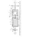
- FIG. 1 is a side sectional view showing an example of the configuration of the motor device according to the present embodiment.
- the motor device according to the embodiment of the present invention is connected to a double-axis motor 1 in which a first rotary shaft 10a and a second rotary shaft 10b protrude from both sides, and a second rotary shaft 10b.
- Rotation direction changer 2 having an input shaft 20a to which torque is input and an output shaft 20b that rotates in the opposite direction with respect to input shaft 20a and outputs torque, and first rotation shaft 10a are provided on both shafts.
- the motor device according to the present embodiment can be applied to a precision stage, a liquid crystal panel manufacturing device, a semiconductor manufacturing device, a vehicle component, a refrigerator, an air conditioner, etc., but a general device having a rotational load 4 is assumed below. To explain.
- the double-axis motor 1 has a substantially cylindrical casing in which a stator 11 is fixed. The first and second protrusions projecting on both sides in the center line direction of the casing.
- a rotor 12 having rotating shafts 10a and 10b is provided.
- the force wheel mounting portion 13 is, for example, a collar portion that holds the force wheel 3 inserted into the first rotating shaft 10a.
- a collar part is an example of the carriage attachment part 13, and if it is comprised so that the carriage 3 can be attached, the shape will not be specifically limited.
- the rotation direction changer 2 includes an input shaft 20a to which the torque of the two-axis motor 1 is input, an output shaft 20b that rotates in the opposite direction with respect to the input shaft 20a, and outputs torque, and the input shaft 20a and the output shaft 20b.
- the magnetic gear mechanism that reverses the rotation direction of the motor includes an inner rotor 21 connected to the input shaft 20a and an outer rotor 22 connected to the output shaft 20b.
- the two-axis motor 1 is connected.
- the second rotary shaft 10b of the double shaft motor 1 and the input shaft 20a of the rotational direction converter 2 are connected by a shaft coupling 7, and the torque of the double shaft motor 1 is input to the rotational direction converter 2.
- FIG. 1 shows an example in which the second rotary shaft 10b and the input shaft 20a are connected by the shaft coupling 7, the second rotary shaft 10b and the input shaft 20a may be configured integrally. Details of the magnetic gear mechanism will be described later.
- a rotation direction converter that converts the rotation direction of the double-shaft motor 1 with a magnetic gear mechanism will be described. However, the rotation direction may be converted with a gear mechanism.
- a rotation load 4 is connected to the output shaft 20 b of the rotation direction changer 2 via a shaft coupling 8.
- the force wheel 3 is a disk-shaped member having an insertion hole at the center, for example.
- the power wheel 3 is fitted on the first rotating shaft 10a of the double-shaft motor 1, is mounted on the power wheel mounting portion 13, and is fixed by a bolt 3a.
- the size and members of the force wheel 3 are not particularly limited, but a shape that allows the frictional force applied to the rotating force wheel 3 to be as small as possible is preferable. Further, in order to cancel the reaction torque applied to the motor device by the small power wheel 3, in addition to the method of increasing the density of the power wheel 3, the plate thickness is increased along the outer peripheral portion of the disk-shaped power wheel. It is desirable to select a shape that can increase the moment of inertia of the vehicle.
- the moment of inertia of the power wheel 3 that can suppress the occurrence of vibration of the motor device is determined so as to satisfy the following expression (3).
- Ia ⁇ a Ib ⁇ b (3)
- Ia is a sum of inertia moments on the input shaft 20a side of the rotation direction converter 2
- Ib is a sum of inertia moments on the output shaft 20b side of the rotation direction converter 2.
- Ia is the inertia of the rotating portion including the power wheel 3, the first and second rotating shafts 10a and 10b, the rotor 12, the shaft coupling 7, the input shaft 20a, and the inner rotor 21. It is a moment.
- Ib is the total sum of the moments of inertia of the rotating portion composed of the outer rotor 22, the output shaft 20 b, the shaft coupling 8, and the rotational load 4.
- a and b are the rotation speeds of the input shaft 20a and the output shaft 20b of the rotation direction changer 2.
- the variable ⁇ in the scope of the claims is the ratio of the rotational speed of the output shaft 20b to the rotational speed of the input shaft 20a, that is, b / a.
- the motor device has a fixing portion 5 for fixing itself to the motor base B.
- the fixing portion 5 is, for example, a substantially trapezoidal member when viewed from the side fixed to the rotating direction changer 2, and the bottom portion of the fixing portion 5 is fixed to the motor base B with a bolt or the like.
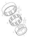
- FIG. 2 is a schematic assembly diagram illustrating a configuration example of the rotation direction changer 2.
- the rotation direction changer 2 is an increase / decrease device having a spatial harmonic type magnetic gear mechanism, for example.
- the rotation direction changer 2 is fitted with a cylindrical inner rotor 21, a cylindrical outer rotor 22 in which the inner rotor 21 fits inside with a gap, and a gap between the inner rotor 21 and the outer rotor 22.
- An intermediate yoke 23 is provided.
- three magnetic pole pairs 211 which are composed of an outer peripheral side N-pole magnet 211 a and an S-pole magnet 211 b magnetized in the thickness direction, are arranged along the circumferential direction.
- the magnet magnetized in the thickness direction means that the outer peripheral surface side and the inner peripheral surface side are magnetized so as to have different polarities.
- the magnet 211a is magnetized on the N and S poles on the outer circumferential surface side and the inner circumferential surface side
- the magnet 211b is magnetized on the S and N poles on the outer circumferential surface side and the inner circumferential surface side, respectively.
- the inner rotor 21 rotates due to the magnetic interaction between the magnetic pole pairs 211 and 221 included in the inner rotor 21 and the outer rotor 22, respectively.
- the inner rotor 21, which has a smaller number of magnetic poles than the outer rotor 22, rotates at a higher rotational speed than the outer rotor 22 in the direction opposite to the rotational direction of the outer rotor 22 (Tetsuya Ikeda, Kenji Nakamura, Osamu Ichinokura , "A Consideration on the Rotor Structure of Permanent Magnet Type Magnetic Gear," Journal of Magnetic Society, 2009, Vol. 33, No. 2, pp. 130-134).
- the gear ratio n is 3/7.
- the gear ratio n is 3/7.
- the output rotation speed of the rotation direction converter 2 decreases with respect to the input rotation speed to the rotation direction converter 2 of the double-axis motor 1
- the output rotation speed is larger than the input rotation speed.
- the present invention can be applied.
- the intermediate yoke 23 holds ten magnetic bodies 231 that are the sum of the numbers 3 and 7 of the magnetic pole pairs 211 and 221 included in the inner rotor 21 and the outer rotor 22, respectively, along the circumferential direction at equal intervals.
- the intermediate yoke 23 is manufactured, for example, by fixing each magnetic body 231 to a resin formed in a cylindrical shape (see, for example, pamphlet of International Publication No. 2009/087408).
- alternating magnetic fields including third-order harmonic components, seventh-order harmonic components, and thirteenth-order harmonic components generated by the magnetic pole pairs 211 and 221 intersect along the radial direction.
- the magnetic body 231 may be a soft magnetic body made of, for example, a magnetic metal, a plurality of stacked magnetic plates, and a green powder compact.
- FIG. 3 is an explanatory diagram for explaining the operational effects of the motor device according to the present embodiment.
- the biaxial motor 1 rotates, torque is output from the first and second rotary shafts 10a and 10b.
- the torque output from the second rotating shaft 10 b is converted in the reverse direction by the rotating direction changer 2 and given to the rotating load 4. That is, the member on the input shaft 20a side and the member on the output shaft 20b side of the rotation direction changer 2 rotate in reverse.
- the torque ⁇ 1 acting on the member on the input shaft 20a side of the rotation direction changer 2 and the torque ⁇ 2 acting on the member on the output shaft 20b side are equal in magnitude and opposite to each other. Therefore, torque that vibrates the motor device does not work when the motor is started.
- the spatial harmonic type magnetic gear mechanism has been described as the rotation direction changer 2, but other magnetic gear mechanisms such as a planetary magnetic gear mechanism may be applied to the present invention.
- a non-magnetic gear mechanism that is, a torque converter having a normal gear mechanism, for example, a planetary gear mechanism, may be applied to the present invention.
- FIG. 4 is a side sectional view showing a configuration example of the motor device according to the first modification.
- the example in which the carriage attachment portion 13 is provided on the first rotating shaft 10a of the double-shaft motor 1 and the carriage 3 is attached to the carriage attachment portion 13 has been described.
- the power wheel 3 may be integrally provided on the first rotating shaft 110 a of the double-axis motor 101.
- FIG. 5 is a side sectional view showing a configuration example of the motor device according to the second modification.
- the fixing portion 5 is provided in the rotational direction changer 2 portion.
- the fixing portion 205 may be provided in the double-axis motor 1.
- FIG. 6 is a side sectional view showing a configuration example of a motor device according to Modification 3.
- the example in which the power wheel 3 is provided on the first rotating shaft 10a of the double-shaft motor 1 and the rotating load 4 is provided on the output shaft 20b of the rotating direction changer 2 has been described.
- a rotational load 304 is provided on the first rotating shaft 310a of the double-shaft motor 301 via the shaft coupling 308, and the power wheel 303 is attached to the output shaft 320b of the rotating direction changer 302. good.
- the configuration in which the power wheel attachment portion 313 is provided on the output shaft 320b and the power wheel 303 is fixed by the bolt 303a is the same as that of the embodiment.
- FIG. 7 is a side sectional view showing a configuration example of a motor device according to Modification 4.
- the fixed portion 5 is provided in the rotation direction converter 302 portion.
- the fixed portion 405 may be provided in the double-axis motor 301 portion.
- the configuration including the power wheel 3 or 303 has been described, but the power wheel 3 or 303 is not included, and the input shaft 20a side of the rotation direction changer 2 or 302 and the output You may comprise so that the diameter, weight, specific gravity, etc. of the rotation part which comprises a motor apparatus may be set so that the torque which acts on the shaft 20b or 320b side may be balanced. Further, when the power wheel 3 or 303 is not provided and the rotational load 4 or 304 is provided on the output shaft 20b or 320b of the rotation direction changer 2 or 302, the motor may be configured as a single-axis motor.
Landscapes
- Engineering & Computer Science (AREA)
- Power Engineering (AREA)
- Mechanical Engineering (AREA)
- General Engineering & Computer Science (AREA)
- Connection Of Motors, Electrical Generators, Mechanical Devices, And The Like (AREA)
- Motor Or Generator Frames (AREA)
Abstract
Description
τ=Iα
即ち、角速度αでモータが回転するためには、モータの回転子及び回転負荷にトルクτが加わるため、モータが設置されているモータベースには、-τのトルクが反力として加わる。このモータベースに働くトルク-τがモータ及びモータベースの振動を引き起こす。
Ia/Ib=α
ことを特徴とする。
但し、
Ia:前記回転方向変換機の前記入力軸側の慣性モーメントの総和
Ib:前記回転方向変換機の前記出力軸側の慣性モーメントの総和
α:前記入力軸の回転数に対する前記出力軸の回転数の比
Ia/Ib=α
ことを特徴とするモータ装置。
但し、
Ia:前記回転方向変換機の前記入力軸側の慣性モーメントの総和
Ib:前記回転方向変換機の前記出力軸側の慣性モーメントの総和
α:前記入力軸の回転数に対する前記出力軸の回転数の比
Ia/Ib=α
ことを特徴とするモータ装置。
但し、
Ia:前記回転方向変換機の前記入力軸側の慣性モーメントの総和
Ib:前記回転方向変換機の前記出力軸側の慣性モーメントの総和
α:前記入力軸の回転数に対する前記出力軸の回転数の比
図1は、本実施の形態に係るモータ装置の一構成例を示した側断面図である。本発明の実施の形態に係るモータ装置は、両側から第1回転軸10a及び第2回転軸10bが突出した両軸モータ1と、第2回転軸10bに接続されており、両軸モータ1のトルクが入力される入力軸20a、入力軸20aに対して逆向きに回転してトルクを出力する出力軸20bを有する回転方向変換機2と、第1回転軸10aに設けられており、両軸モータ1が回転した場合に回転方向変換機2の入力軸20a及び出力軸20bに働く反作用トルクを均衡させるための勢車3と、回転方向変換機2の出力軸20bに接続された回転負荷4とを備える。本実施の形態に係るモータ装置は、精密ステージ、液晶パネル製造装置、半導体製造装置、車両部品、冷蔵庫、エアコン等に適用することができるが、以下では回転負荷4を有する一般的な装置を想定して説明する。
Ia×a=Ib×b…(3)
a、bは、回転方向変換機2の入力軸20a及び出力軸20bの回転数である。つまり、入力軸20aの回転数:出力軸20bの回転数=a:bである。なお、特許請求項の範囲における変数αは、入力軸20aの回転数に対する出力軸20bの回転数の比、即ちb/aである。
内側ロータ21の外周面には、厚さ方向に着磁された外周面側N極の磁石211a及びS極の磁石211bからなる磁極対211が円周方向に沿って3個配置されている。
外側ロータ22の内周面には、厚さ方向に着磁された内周面側N極の磁石221a及びS極の磁石221bからなる磁極対221が円周方向に沿って7個配置されている。ここで厚さ方向に着磁された磁石とは、外周面側及び内周面側が異極となるよう着磁されていることを意味する。例えば、磁石211aは、外周面側及び内周面側夫々がN極及びS極に着磁され、磁石211bは、外周面側および内周面側夫々がS極及びN極に着磁されている。
なお、両軸モータ1の回転方向変換機2への入力回転数に対して、回転方向変換機2の出力回転数が少なくなる場合について説明したが、入力回転数に対して出力回転数が多くなる場合にも本発明は適用できる。
図3は、本実施の形態に係るモータ装置の作用効果を説明するための説明図である。両軸モータ1が回転した場合、第1及び第2回転軸10a,10bからトルクが出力される。特に第2回転軸10bから出力されたトルクは、回転方向変換機2でその方向が逆向きに変換され、回転負荷4に与えられる。つまり、回転方向変換機2の入力軸20a側の部材と、出力軸20b側の部材とが逆回転する。回転方向変換機2の入力軸20a側の部材に働くトルクτ1と、出力軸20b側の部材に働くトルクτ2は、大きさが等しく逆向きである。従って、モータ始動時にモータ装置を振動させるようなトルクは働かない。
図4は、変形例1に係るモータ装置の一構成例を示した側断面図である。図1に示す実施の形態では、両軸モータ1の第1回転軸10aに勢車取付部13を設け、該勢車取付部13に勢車3を取り付ける例を説明したが、図4に示すように、両軸モータ101の第1回転軸110aに勢車3を一体的に設けても良い。
図5は、変形例2に係るモータ装置の一構成例を示した側断面図である。図1に示す実施の形態においては、固定部5を回転方向変換機2部分に設けていたが、図5に示すように、固定部205を両軸モータ1に設けても良い。
図6は、変形例3に係るモータ装置の一構成例を示した側断面図である。図1に示す実施の形態においては、両軸モータ1の第1回転軸10aに勢車3を設け、回転方向変換機2の出力軸20bに回転負荷4を設けた例を説明したが、図6に示すように、両軸モータ301の第1回転軸310aに軸継手308を介して回転負荷304を設け、回転方向変換機302の出力軸320bに勢車303を取り付けるように構成しても良い。出力軸320bに勢車取付部313を設け、勢車303をボルト303aで固定する構成は、実施の形態と同様である。
図7は、変形例4に係るモータ装置の一構成例を示した側断面図である。変形例3においては、固定部5を回転方向変換機302部分に設けていたが、図7に示すように、固定部405を両軸モータ301部分に設けても良い。
2 回転方向変換機
3 勢車
4 回転負荷
5 固定部
10a 第1回転軸
10b 第2回転軸
11 固定子
12 回転子
13 勢車取付部
20a 入力軸
20b 出力軸
21 内側ロータ
22 外側ロータ
23 中間ヨーク
B モータベース
Claims (8)
- 両側から回転軸が突出した両軸モータと、
該回転軸の一端側に接続されており、該両軸モータのトルクが入力される入力軸、該入力軸に対して逆向きに回転して該トルクを出力する出力軸を有する回転方向変換機と、
前記回転軸の他端側又は前記回転方向変換機の出力軸に設けられており、前記両軸モータが回転した場合に前記回転方向変換機の入力軸及び出力軸に働く反作用トルクを均衡させるための勢車と
を備えることを特徴とするモータ装置。 - 前記回転方向変換機の出力軸又は前記回転軸の他端側に接続された回転負荷を備え、
前記勢車、前記両軸モータ、前記回転方向変換機及び前記回転負荷の慣性モーメントと、前記回転方向変換機の回転数の比とは下記式を満たす
Ia/Ib=α
ことを特徴とする請求項1に記載のモータ装置。
但し、
Ia:前記回転方向変換機の前記入力軸側の慣性モーメントの総和
Ib:前記回転方向変換機の前記出力軸側の慣性モーメントの総和
α:前記入力軸の回転数に対する前記出力軸の回転数の比 - 両側から回転軸が突出した両軸モータと、
該回転軸の一端側に接続されており、該両軸モータのトルクが入力される入力軸、該入力軸に対して逆向きに回転して該トルクを出力する出力軸を有する回転方向変換機と、
前記回転軸の他端側又は前記回転方向変換機の出力軸に設けられており、前記両軸モータが回転した場合に前記回転方向変換機の入力軸及び出力軸に働く反作用トルクを均衡させるための勢車が取り付けられる勢車取付部と
を備えることを特徴とするモータ装置。 - 前記勢車取付部に取り付けられた勢車を備える
ことを特徴とする請求項3に記載のモータ装置。 - 両側から回転軸が突出した両軸モータと、
該回転軸の一端側に接続されており、該両軸モータのトルクが入力される入力軸、該入力軸に対して逆向きに回転して該トルクを出力する出力軸を有する回転方向変換機と、
前記回転方向変換機の出力軸又は前記回転軸の他端側に接続された回転負荷と
を備え、
前記両軸モータ、前記回転方向変換機及び前記回転負荷の慣性モーメントと、前記回転方向変換機の回転数の比とは下記式を満たす
Ia/Ib=α
ことを特徴とするモータ装置。
但し、
Ia:前記回転方向変換機の前記入力軸側の慣性モーメントの総和
Ib:前記回転方向変換機の前記出力軸側の慣性モーメントの総和
α:前記入力軸の回転数に対する前記出力軸の回転数の比 - 回転軸が突出した一軸モータと、
該回転軸に接続されており、該一軸モータのトルクが入力される入力軸、該入力軸に対して逆向きに回転して該トルクを出力する出力軸を有する回転方向変換機と、
前記回転方向変換機の出力軸に接続された回転負荷と
を備え、
前記一軸モータ、前記回転方向変換機及び前記回転負荷の慣性モーメントと、前記回転方向変換機の回転数の比とは下記式を満たす
Ia/Ib=α
ことを特徴とするモータ装置。
但し、
Ia:前記回転方向変換機の前記入力軸側の慣性モーメントの総和
Ib:前記回転方向変換機の前記出力軸側の慣性モーメントの総和
α:前記入力軸の回転数に対する前記出力軸の回転数の比 - 前記回転方向変換機は、
前記入力軸に入力されたトルクを前記出力軸に伝達させる磁気歯車機構を有する
ことを特徴とする請求項1乃至請求項6のいずれか一つに記載のモータ装置。 - 前記両軸モータ若しくは前記一軸モータ、又は前記回転方向変換機を外部の被設置体に固定するための固定部を備える
ことを特徴とする請求項1乃至請求項7のいずれか一つに記載のモータ装置。
Priority Applications (4)
| Application Number | Priority Date | Filing Date | Title |
|---|---|---|---|
| US13/983,744 US9273557B2 (en) | 2011-02-17 | 2012-02-02 | Motor device |
| EP12746744.7A EP2677638B1 (en) | 2011-02-17 | 2012-02-02 | Motor system |
| CN201280008621.3A CN103370858B (zh) | 2011-02-17 | 2012-02-02 | 电动机装置 |
| JP2012557877A JP5578243B2 (ja) | 2011-02-17 | 2012-02-02 | モータ装置 |
Applications Claiming Priority (2)
| Application Number | Priority Date | Filing Date | Title |
|---|---|---|---|
| JP2011032405 | 2011-02-17 | ||
| JP2011-032405 | 2011-02-17 |
Publications (1)
| Publication Number | Publication Date |
|---|---|
| WO2012111440A1 true WO2012111440A1 (ja) | 2012-08-23 |
Family
ID=46672371
Family Applications (1)
| Application Number | Title | Priority Date | Filing Date |
|---|---|---|---|
| PCT/JP2012/052337 Ceased WO2012111440A1 (ja) | 2011-02-17 | 2012-02-02 | モータ装置 |
Country Status (5)
| Country | Link |
|---|---|
| US (1) | US9273557B2 (ja) |
| EP (1) | EP2677638B1 (ja) |
| JP (1) | JP5578243B2 (ja) |
| CN (1) | CN103370858B (ja) |
| WO (1) | WO2012111440A1 (ja) |
Cited By (2)
| Publication number | Priority date | Publication date | Assignee | Title |
|---|---|---|---|---|
| US20160006335A1 (en) * | 2013-01-11 | 2016-01-07 | Hitachi Metals, Ltd. | Magnetic gear device |
| JPWO2023233573A1 (ja) * | 2022-06-01 | 2023-12-07 |
Families Citing this family (4)
| Publication number | Priority date | Publication date | Assignee | Title |
|---|---|---|---|---|
| CN110611397B (zh) * | 2019-10-16 | 2020-11-06 | 北京泓慧国际能源技术发展有限公司 | 飞轮储能装置 |
| CN110847813B (zh) * | 2019-10-29 | 2021-04-02 | 芜湖职业技术学院 | 一种机械式地下施工钻机组件 |
| JPWO2023042439A1 (ja) * | 2021-09-16 | 2023-03-23 | ||
| CN115199691B (zh) * | 2022-08-15 | 2024-01-26 | 重庆交通大学 | 基于同轴磁性齿轮的大惯质比惯容器 |
Citations (2)
| Publication number | Priority date | Publication date | Assignee | Title |
|---|---|---|---|---|
| JPH034048A (ja) | 1989-06-01 | 1991-01-10 | Bridgestone Corp | 防振支持装置 |
| WO2009087408A2 (en) | 2008-01-11 | 2009-07-16 | Magnomatics Limited | Magnetic drive systems |
Family Cites Families (9)
| Publication number | Priority date | Publication date | Assignee | Title |
|---|---|---|---|---|
| DE69032945T2 (de) * | 1989-10-20 | 1999-09-16 | Applied Materials, Inc. | Robotereinrichtung |
| US5376862A (en) * | 1993-01-28 | 1994-12-27 | Applied Materials, Inc. | Dual coaxial magnetic couplers for vacuum chamber robot assembly |
| US5751078A (en) * | 1996-10-03 | 1998-05-12 | Lockheed Martin Corp. Missiles & Space | Reactionless, momentum compensated payload positioner |
| WO2004008611A1 (ja) * | 2002-07-10 | 2004-01-22 | Nikon Corporation | モータ、ロボット、基板ローダ及び露光装置 |
| US6762524B2 (en) * | 2002-08-01 | 2004-07-13 | Albert Six | Magnetic drive system for a vehicle differential |
| JP2005080399A (ja) * | 2003-08-29 | 2005-03-24 | Fuji Xerox Co Ltd | 回転駆動装置及びこれを用いた処理装置 |
| CN2704154Y (zh) * | 2004-04-06 | 2005-06-08 | 常州市德益机电制造有限公司 | 电动自行车用无刷高速有齿电机 |
| JP4207939B2 (ja) * | 2005-08-31 | 2009-01-14 | トヨタ自動車株式会社 | 駆動装置およびこれを備える動力出力装置 |
| CN201557004U (zh) * | 2009-11-24 | 2010-08-18 | 南京依维柯汽车有限公司 | 纯电动汽车双输出电机 |
-
2012
- 2012-02-02 EP EP12746744.7A patent/EP2677638B1/en not_active Not-in-force
- 2012-02-02 WO PCT/JP2012/052337 patent/WO2012111440A1/ja not_active Ceased
- 2012-02-02 CN CN201280008621.3A patent/CN103370858B/zh not_active Expired - Fee Related
- 2012-02-02 US US13/983,744 patent/US9273557B2/en not_active Expired - Fee Related
- 2012-02-02 JP JP2012557877A patent/JP5578243B2/ja not_active Expired - Fee Related
Patent Citations (2)
| Publication number | Priority date | Publication date | Assignee | Title |
|---|---|---|---|---|
| JPH034048A (ja) | 1989-06-01 | 1991-01-10 | Bridgestone Corp | 防振支持装置 |
| WO2009087408A2 (en) | 2008-01-11 | 2009-07-16 | Magnomatics Limited | Magnetic drive systems |
Non-Patent Citations (4)
| Title |
|---|
| IKEDA TETSUYA; NAKAMURA KENJI; ICHINOKURA OSAMU: "A Way to Improve Efficiency of Permanent-Magnet Magnetic Gears", JIKIGAKKAI RONBUNSHI, vol. 33, no. 2, 2009, pages 130 - 134, XP055135295, DOI: doi:10.3379/msjmag.0901RG8016 |
| See also references of EP2677638A4 |
| TETSUYA IKEDA ET AL.: "A Way to Improve Efficiency of Permanent- Magnet Magnetic Gears", JIKI GAKKAI RONBUNSHI, vol. 33, no. 2, February 2009 (2009-02-01), pages 130 - 134, XP055135295 * |
| TETSUYA IKEDA ET AL.: "Consideration of Rotor Structure in Permanent- Magnet Magnetic Gears", JIKI GAKKAI RONBUNSHI, vol. 34, no. 3, March 2010 (2010-03-01), pages 380 - 384, XP055135294 * |
Cited By (4)
| Publication number | Priority date | Publication date | Assignee | Title |
|---|---|---|---|---|
| US20160006335A1 (en) * | 2013-01-11 | 2016-01-07 | Hitachi Metals, Ltd. | Magnetic gear device |
| JPWO2023233573A1 (ja) * | 2022-06-01 | 2023-12-07 | ||
| WO2023233573A1 (ja) * | 2022-06-01 | 2023-12-07 | 三菱電機株式会社 | 磁気ギア装置 |
| JP7686150B2 (ja) | 2022-06-01 | 2025-05-30 | 三菱電機株式会社 | 磁気ギア装置 |
Also Published As
| Publication number | Publication date |
|---|---|
| CN103370858B (zh) | 2015-12-23 |
| EP2677638A4 (en) | 2016-03-30 |
| EP2677638B1 (en) | 2018-04-25 |
| US9273557B2 (en) | 2016-03-01 |
| JP5578243B2 (ja) | 2014-08-27 |
| JPWO2012111440A1 (ja) | 2014-07-03 |
| US20130315705A1 (en) | 2013-11-28 |
| EP2677638A1 (en) | 2013-12-25 |
| CN103370858A (zh) | 2013-10-23 |
Similar Documents
| Publication | Publication Date | Title |
|---|---|---|
| JP5578243B2 (ja) | モータ装置 | |
| US9680359B2 (en) | Drive device for electric vehicle with respective motor generators having a coprime number of fasteners relative to each other | |
| JP5348182B2 (ja) | 減速機付きモータ | |
| US20140015362A1 (en) | Sphere zone coupling of magnetic devices and multiple applications | |
| JP6313443B2 (ja) | パラレルハイブリッド動力伝達機構 | |
| US10862369B2 (en) | Power unit and motor unit for wave gear speed reducer | |
| JP2019086150A (ja) | 動力源を有する減速機 | |
| JP2016182004A (ja) | 減速機付モータ | |
| CN110774880B (zh) | 车辆用驱动装置 | |
| JP5801688B2 (ja) | 駆動装置 | |
| WO2020050242A1 (ja) | 駆動装置 | |
| CN103891109B (zh) | 驱动装置 | |
| JP7088312B2 (ja) | 渦電流式ダンパ | |
| CN114513087A (zh) | 齿轮马达 | |
| JP2010260476A (ja) | インホイールモータ駆動装置および車両用モータ駆動装置 | |
| CN112713737B (zh) | 一种面向机器人关节的二级磁齿轮传动电机 | |
| JP2004046023A (ja) | 回転電機による回転体駆動法 | |
| WO2013069607A1 (ja) | 歯車伝動装置 | |
| JP4831319B2 (ja) | 減速機付きモータ | |
| KR100999639B1 (ko) | 비틀림 진동을 저감할 수 있는 댐핑장치 | |
| JP2015204725A (ja) | モータのロータ構造 | |
| JP2009210028A (ja) | 遊星歯車装置 | |
| KR20090066518A (ko) | 차량의 수동식 클러치의 노이즈 저감 장치 | |
| JP2012228161A (ja) | 動力分割装置 |
Legal Events
| Date | Code | Title | Description |
|---|---|---|---|
| WWE | Wipo information: entry into national phase |
Ref document number: 201280008621.3 Country of ref document: CN |
|
| 121 | Ep: the epo has been informed by wipo that ep was designated in this application |
Ref document number: 12746744 Country of ref document: EP Kind code of ref document: A1 |
|
| ENP | Entry into the national phase |
Ref document number: 2012557877 Country of ref document: JP Kind code of ref document: A |
|
| WWE | Wipo information: entry into national phase |
Ref document number: 13983744 Country of ref document: US |
|
| NENP | Non-entry into the national phase |
Ref country code: DE |
|
| WWE | Wipo information: entry into national phase |
Ref document number: 2012746744 Country of ref document: EP |