WO2012111458A1 - Dispositif de diagnostic radiographique et procédé d'affichage d'images - Google Patents
Dispositif de diagnostic radiographique et procédé d'affichage d'images Download PDFInfo
- Publication number
- WO2012111458A1 WO2012111458A1 PCT/JP2012/052525 JP2012052525W WO2012111458A1 WO 2012111458 A1 WO2012111458 A1 WO 2012111458A1 JP 2012052525 W JP2012052525 W JP 2012052525W WO 2012111458 A1 WO2012111458 A1 WO 2012111458A1
- Authority
- WO
- WIPO (PCT)
- Prior art keywords
- image
- ray
- grid
- subject
- head
- Prior art date
- Legal status (The legal status is an assumption and is not a legal conclusion. Google has not performed a legal analysis and makes no representation as to the accuracy of the status listed.)
- Ceased
Links
Images




Classifications
-
- A—HUMAN NECESSITIES
- A61—MEDICAL OR VETERINARY SCIENCE; HYGIENE
- A61B—DIAGNOSIS; SURGERY; IDENTIFICATION
- A61B6/00—Apparatus or devices for radiation diagnosis; Apparatus or devices for radiation diagnosis combined with radiation therapy equipment
- A61B6/46—Arrangements for interfacing with the operator or the patient
- A61B6/461—Displaying means of special interest
-
- A—HUMAN NECESSITIES
- A61—MEDICAL OR VETERINARY SCIENCE; HYGIENE
- A61B—DIAGNOSIS; SURGERY; IDENTIFICATION
- A61B6/00—Apparatus or devices for radiation diagnosis; Apparatus or devices for radiation diagnosis combined with radiation therapy equipment
- A61B6/42—Arrangements for detecting radiation specially adapted for radiation diagnosis
- A61B6/4291—Arrangements for detecting radiation specially adapted for radiation diagnosis the detector being combined with a grid or grating
-
- A—HUMAN NECESSITIES
- A61—MEDICAL OR VETERINARY SCIENCE; HYGIENE
- A61B—DIAGNOSIS; SURGERY; IDENTIFICATION
- A61B6/00—Apparatus or devices for radiation diagnosis; Apparatus or devices for radiation diagnosis combined with radiation therapy equipment
- A61B6/42—Arrangements for detecting radiation specially adapted for radiation diagnosis
- A61B6/4208—Arrangements for detecting radiation specially adapted for radiation diagnosis characterised by using a particular type of detector
Definitions
- the present invention relates to an X-ray diagnostic imaging apparatus and an image display method, and particularly to a technique for displaying a captured image of a subject obtained by radiography using an X-ray flat panel detector.
- a device that irradiates an object with radiation and detects an intensity distribution of the radiation transmitted through the object to obtain a photographed image of the object has been widely used in industrial nondestructive inspection and medical diagnosis.
- a film / screen method for X-rays can be mentioned.
- a method for obtaining a high-quality captured image by converting a captured image into an electrical signal, processing the electrical signal, and reproducing the image as a visible image on a CRT or the like has been demanded.
- an apparatus for taking a photographed image in the same manner using an X-ray flat panel detector has been developed. These systems have a very wide dynamic range compared to conventional radiation systems using photosensitive films, and have the practical advantage of being able to obtain captured images that are not affected by fluctuations in radiation exposure. Have.
- Such X-ray flat panel detectors have been downsized to the size of conventional analog cassettes due to technological advances, and so-called mobile digital X-ray imaging devices called electronic cassettes have been developed.
- Such an X-ray flat panel detector is generally the same size as a conventional analog cassette and has a large rectangular size in order to use an existing imaging table without updating it.
- the rectangular size depending on the size of the subject, there may be a case where it is inserted vertically with respect to the imaging table or a case where it is inserted horizontally.
- FIG. 1A and 1B are explanatory views showing the relationship between the insertion direction and the head and foot direction of an X-ray flat panel detector in the background art, where FIG. 1A shows vertical insertion and FIG. 1B shows horizontal insertion. As shown in FIG.
- the image when the image is vertically inserted (meaning that the flat detector 102 is inserted vertically with respect to the head-and-foot direction 101 of the standing position imaging stand 100), the image is displayed on the image display device 103. Although displayed in the vertical direction (the head of the subject imaged in the image is up), when inserted horizontally as shown in FIG. 1B, the image is displayed in the horizontal direction (image was captured in the image). The head of the subject is displayed on the right or left).
- the user rotates an image with a GUI (Graphical User Interface) or detects the direction of a Flat Pnel Detector (hereinafter abbreviated as “FPD”) which is a kind of X-ray flat panel detector.
- GUI Graphic User Interface
- FPD Flat Pnel Detector
- Patent Document 1 proposes a technique of embedding marks in the corners of an image and inverting / rotating the image.
- a mark may be inserted into a region in which a subject is imaged in a captured image, and the mark may interfere with diagnosis. Furthermore, since the mark has to be inserted, the workflow is hindered.
- An object of the present invention is to solve the above-described problems and provide a technique capable of accurately displaying the head and foot direction on the image display device regardless of the insertion direction of the X-ray flat panel detector.
- the present invention determines whether the fringe direction caused by the grid included in the image data is vertical or horizontal, and based on the determination result, the region of the subject imaged in the image (hereinafter referred to as “ The image is rotated so that the head direction in the “subject image” matches the upward direction on the display screen of the image display unit, and the rotated image is displayed.
- the present invention it is possible to provide a technique capable of accurately displaying the head and foot direction on the display unit regardless of the insertion direction of the X-ray flat panel detector.
- the X-ray diagnostic imaging apparatus is disposed so as to face an X-ray tube that irradiates a subject with X-rays, a grid that removes scattered radiation components generated by the subject, and the X-ray tube.
- An X-ray flat panel detector that detects transmitted X-rays of the subject and outputs image data, an image display unit that displays an image based on the image data, and a fringe direction caused by the grid included in the image data
- the head direction in the region (subject image) of the subject photographed in the image is determined based on the determination result by the grid stripe direction determination unit and the grid stripe direction determination unit.
- An image rotation unit that rotates the image so as to coincide with the upward direction on the display screen of the image display unit.
- the image display unit displays the rotated image.
- the grid stripe direction determination unit performs a fast Fourier transform process on the image data, the value of the grid stripe frequency response, or the ratio between the grid stripe frequency response and the frequency response in the vicinity of the grid stripe frequency, May be used to determine the grid stripe direction.
- the grid stripe direction determination unit may perform the fast Fourier transform process on a direct X-ray region in which X-rays are directly incident on the image.
- the grid stripe direction determining unit determines the grid stripe frequency according to an imaging distance between the subject and the X-ray tube when the image data is acquired by the X-ray image diagnostic apparatus. May be.
- the image rotation unit further includes a detector insertion direction storage unit that stores insertion direction information indicating an insertion direction of the X-ray flat panel detector with respect to an imaging table that stores the grid and the X-ray flat panel detector.
- the rotation direction of the image is determined based on the determination result by the grid stripe direction determination unit and the insertion direction information so that the head direction of the subject in the image matches the upward direction in the image display unit.
- the image may be rotated.
- the insertion direction information is a parameter that associates the head-and-foot direction of the imaging table with the insertion direction of the X-ray plane device with respect to the imaging table, and rotates the image 180 degrees and rotates 90 degrees to the right.
- the information may be associated with either left 90 ° rotation.
- the image rotation unit extracts a subject region where the subject is imaged in the image, detects a head-foot direction of the subject, and based on the detection result, the rotation direction of the image is rotated to the right or It may be determined whether the rotation is counterclockwise.
- a storage unit that stores the rotation information determined by the image rotation unit along with the image data may be further provided.
- the image display method is obtained by imaging the subject using an X-ray diagnostic imaging apparatus including a grid that removes scattered radiation components generated by the subject and an X-ray flat panel detector.
- a step of reading the obtained image data, a step of determining whether the stripe direction caused by the grid included in the image data is vertical or horizontal, and an image based on the image data based on the determination result A step of rotating the image so that a head direction in the region of the subject (subject image) coincides with an upward direction on a display screen on which the image is displayed; and the rotated image is displayed on the display screen.
- a step of displaying is obtained by imaging the subject using an X-ray diagnostic imaging apparatus including a grid that removes scattered radiation components generated by the subject and an X-ray flat panel detector.
- FIG. 2 is a schematic diagram showing a schematic configuration of the X-ray image diagnostic apparatus 10 according to the present embodiment.
- the X-ray diagnostic imaging apparatus 10 is disposed so as to face the X-ray tube 1 that irradiates the subject 20 with X-rays, the grid 2 that removes scattered radiation components generated by the subject 20, and the X-ray tube 1.
- An X-ray plane detector 3 for detecting transmitted X-rays of the specimen 20, an imaging table 4 in which the grid 2 and the X-ray plane detector 3 are stored, and storage of image data output from the X-ray plane detector 3
- an image processing device 5 that performs image processing
- an image display device 6 that displays image data stored in the image processing device 5.
- the image processing device 5 includes an image storage unit 5a for storing image data, image data output from the X-ray flat panel detector 3, or a scattered light removal grid (hereinafter referred to as a captured image read by the image processing device 5).
- a grid stripe direction discriminating section 5b for discriminating whether the stripe direction of 2 is vertical or horizontal, and a detector insertion direction in which insertion direction information of the X-ray flat panel detector 3 in the imaging table 4 is stored.
- a storage unit 5c, and an image rotation unit 5d that rotates an image stored in the image storage unit 5a based on information from the insertion direction information and the grid stripe direction determination unit 5b.
- the image storage unit 5a and the detector insertion direction storage unit 5c are configured to include a nonvolatile or volatile storage device, for example, a memory, a magnetic disk, or a nonvolatile memory included in the hardware configuring the image processing device 5.
- the Further, the grid stripe direction discriminating unit 5b and the image rotating unit 5d perform fast Fourier transform (FFT Fourier Transform; hereinafter abbreviated as “FFT”) on the read image data, and give a response response of the grid stripe frequency.
- FFT fast Fourier transform
- a program for causing a computer to execute an image display method including a step of calculating and determining a grid stripe direction based on the calculated result, a step of performing image rotation processing using the determination result, and hardware for executing the program And are configured by cooperation.
- the grid stripe direction of the image data output from the X-ray flat panel detector 3 provided in the X-ray image diagnostic apparatus 10 is determined and the image is rotated.
- the image processing apparatus 5 may read the image data of the photographed image and perform image processing similar to the above on the image data.
- FIG. 3 is a flowchart showing a flow of image display processing of the X-ray image diagnostic apparatus according to the first embodiment. Hereinafter, description will be made along the order of steps in FIG.
- Step S1 Image data is acquired from the X-ray flat panel detector 3 and temporarily stored in the image storage unit 5a.
- the grid stripe direction determining unit 5b determines the grid stripe direction included in the image data.
- the vertical direction flag is stored.
- the horizontal direction flag is stored (S1). Details of this step will be described later.
- Step S2 The image rotation unit 5d reads insertion direction information indicating the insertion direction of the X-ray flat panel detector 3 with respect to the imaging table 4 from the detector insertion direction storage unit 5c.
- the insertion direction information determines whether to insert from the right side or the left side of the imaging table when the X-ray diagnostic imaging apparatus 1 or the imaging table 4 is installed, and is stored as a setting value when the imaging table 4 is installed.
- the head-and-foot direction of the imaging platform 4 is expressed as a parameter corresponding to the determined insertion direction, and the image rotation direction corresponding to the parameter is associated and stored as insertion direction information.
- the image rotation unit 5d uses the insertion direction information read from the detector insertion direction storage unit 5c and the grid stripe direction information in step S1 to adjust the image to the head and foot direction of the image display device 6. It is determined whether or not rotation of the data in the direction of the head and feet is unnecessary (S2). If unnecessary, the process proceeds to step S4. If necessary, the process proceeds to step S3.
- Step S3 The image rotation unit 5d performs head and foot rotation processing (S3).
- the grid stripe direction is vertical, it is rotated 180 degrees, and when the grid stripe direction is horizontal, it is rotated 90 degrees.
- the history of image rotation and information indicating the rotation direction such as “IMEGEROTATION: 1”, as supplementary information of DICOM (note: a kind of medical image communication protocol)
- Saving as DICOM incidental information is only one example of saving, and may be saved as image incidental information of another project, or image rotation history and rotation direction are associated with information for identifying an image. May be saved.
- Step S4 The image processing device 5 executes processing necessary before image display processing, such as grid stripe removal processing, and displays an image after rotation processing or an image that does not require rotation on the image display device 6 (S4). At this time, the up-and-down direction of the image display device 6 and the head-and-foot direction of the subject image included in the displayed captured image match.
- the image data in the image storage unit 5a is updated to the image data after the rotation process, and the process ends.
- FIG. 4 is a flowchart showing a flow of grid stripe direction discrimination processing.
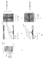
- 5A and 5B are explanatory diagrams showing the contents of the grid stripe direction discrimination process, where FIG. 5A shows the scanning direction of the line, FIG. 5B shows the frequency response response when the grid stripe direction is vertical, and (c ) Shows the relationship between the line direction and the grid stripe direction being vertical, (d) shows the frequency response response when the grid stripe direction is horizontal, and (e) is the case where the line direction and grid stripe direction are horizontal. Shows the relationship.
- description will be made along the order of steps in FIG.
- Step S11 The grid stripe direction determination unit 5b scans an arbitrary line in the image 50 (S11).
- Line scanning is preferably performed in the vicinity of the center of the image 50 in order to avoid a position in the image 50 where grid stripes are difficult to detect, such as an aperture region.
- all line processing may be performed, but processing may be performed for each predetermined number of lines in order to shorten processing time.
- smoothing processing or the like may be performed after the FFT processing.
- line scanning is advanced at 100 line intervals. Furthermore, an upper limit value (for example, n times) of the number of line scans is set. If the number of line scans is less than or equal to the upper limit (corresponding to “No”), the process proceeds to step S12. If line scanning has been performed for the upper limit number of times, it is determined that line scanning has ended (corresponding to “Yes”), and the process proceeds to step S16.
- an upper limit value for example, n times
- the line 50t that is 100 lines above the center line 50m of the image 50 is read, and in the next loop, the line that is 100 lines below the center line 50m.
- the line scan is advanced to 50u.
- Step S12 The grid stripe direction discriminating unit 5b performs an FFT process on one line read in step S11 (S12).
- the grid stripe direction determination unit 5b determines the presence or absence of grid stripes based on the response Rg of the grid stripe frequency (S13).
- the grid stripe direction determination unit 5b determines that there is a grid when the ratio between the response Rg of the grid stripe frequency and the response Ra of the neighboring frequency is equal to or greater than the threshold th.
- the threshold value th is 2.0.
- step S14 If it is determined that there are grid stripes, the process proceeds to step S14. If it is determined that there is no grid stripes, the process proceeds to step S15, the line scanning position is changed, and the process returns to step S11.
- the grid stripe direction determination unit 5b may be configured to determine that there is a grid stripe when the response Rg of the grid stripe frequency is equal to or greater than a predetermined value.
- Step S15 The grid stripe direction discriminating unit 5b adds a vertical direction flag and ends the grid stripe direction discrimination process (S15).
- Step S16 If grid stripes are not detected even after the processes from step S11 to step S14 are repeated a predetermined number of times, the grid stripe direction discriminating unit 5b attaches a horizontal direction flag and ends the grid stripe direction discrimination processing (S16).
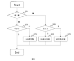
- FIG. 6 is a flowchart showing the flow of the head and foot rotation process.
- FIG. 7 is an explanatory diagram showing the contents of the head-and-foot rotation process in the table for taking a standing position.
- the head direction 71h and the foot direction 71l are determined in advance in the position table photographing base 70 (hereinafter, abbreviated as "photographing base 70"). It is also assumed that the image reading start position 3a and the image reading direction 3b of the X-ray flat panel detector 3 are known. Further, in the captured image obtained from the X-ray flat panel detector 3, the upper left corner of the display screen in the image display device 6 corresponds to the image reading start position 3a, and the direction from the left to the right of the display screen and the image reading direction 3b. It is known that the captured image is displayed so that the direction along the line matches.
- the imaging table 70 and the insertion direction of the X-ray flat panel detector 3 it is inserted such that the long side of the rectangular X-ray flat panel detector 3 coincides with the long side of the imaging table 70.
- the case of inserting from the right side of the top surface of the imaging table 70 and the case of inserting from the left side can be considered. Therefore, in the following, four types of insertion direction information of “vertical insertion and right insertion”, “vertical insertion and left insertion”, “lateral insertion and right insertion”, and “lateral insertion and left insertion” will be described.
- the parameter indicating the relationship between the head and foot directions 71h and 71l of the imaging table 70 and the insertion direction (vertical insertion and right insertion) of the X-ray flat panel detector 3 is set to “0”.
- the parameter “0” as described above, the upper left corner of the display screen in the image display device 6 corresponds to the image reading start position 3a, and the captured image read from the X-ray flat panel detector 3 corresponds to the image reading start position 3a.
- the head direction of the captured image coincides with the upward direction on the display screen of the X image display device 6 (“state 0 before image rotation”). Equivalent to '"). Therefore, since the image rotation process is unnecessary, insertion direction information “0: output as it is” indicating that the image rotation is unnecessary is stored for the parameter 0.
- the parameter indicating the relationship between the head and foot directions 71h and 71l of the imaging table 70 and the insertion direction (vertical insertion and left insertion) of the X-ray flat panel detector 3 is set to “1”.
- the image reading start position 3 a of the X-ray flat panel detector 3 is located on the foot side of the imaging table 70. Therefore, the foot side of the subject 20 is imaged on the image reading start position 3 a side of the X-ray flat panel detector 3.
- the parameter indicating the relationship between the head and foot directions 71h and 71l of the imaging table 70 and the insertion direction (lateral insertion and right insertion) of the X-ray flat panel detector 3 is set to “2”.
- the image reading start position 3 a of the X-ray flat panel detector 3 is located on the foot side of the imaging table 70.
- the image reading direction 3b coincides with the head direction 71h of the imaging table 70. Therefore, the foot side of the subject 20 is photographed on the image readout start position 3a side of the X-ray flat panel detector 3, and the head direction of the subject 20 is photographed along the image readout direction 3b.
- the parameter indicating the relationship between the head and foot directions 71h and 71l of the imaging base 70 and the insertion direction (lateral insertion and left insertion) of the X-ray flat panel detector 3 is set to “3”.
- the image reading start position 3 a of the X-ray flat panel detector 3 is located on the head side of the imaging table 70.
- the image reading direction 3b coincides with the foot direction 71l of the imaging table 70. Therefore, the head side of the subject is photographed on the image readout start position 3a side of the X-ray flat panel detector 3, and the foot direction 71l of the subject 20 is photographed along the image readout direction 3b.
- the above four cases have been described.
- the user decides either right insertion or left insertion when installing the imaging stand 70.
- two patterns of insertion direction information corresponding to the determined insertion direction and the insertion direction (vertical insertion, horizontal insertion) of the X-ray flat panel detector 3 are stored in advance in the detector insertion direction information storage unit 5c as set values. Keep it.
- the image rotation unit 5d performs the head-foot rotation process
- the image rotation unit 5d determines which of the two patterns of insertion direction information corresponds from the detector insertion direction storage unit 5c, and performs the head-foot rotation process.
- Step S21 The image rotation unit 5d reads the vertical and horizontal flags stored in the grid stripe direction discrimination process. If the value is vertical, the process proceeds to step S22. If the value is horizontal, the process proceeds to step S24 (S21).
- Step S22 The image rotation unit 5d refers to the insertion direction information stored in the detector insertion direction storage unit 5c, and proceeds to the 0 or 1 branch. In the case of 0, it is output as it is. If 1, the process proceeds to step S23 (S22).
- Step S23 The image rotation unit 5d rotates the image by 180 degrees and outputs it (S23).
- Step S24 In the case of the horizontal flag, the image rotation unit 5d refers to the insertion direction information in the horizontal direction stored in the detector insertion direction storage unit 5c, and proceeds to branch 2 or 3. If it is 2, the process proceeds to step S25, and if it is 3, the process proceeds to step S26 (S24).
- Step S25 The image rotation unit 5d rotates the image 90 degrees to the left and outputs it, and ends the head-foot rotation process (S25).
- Step S26 The image rotation unit 5d rotates the image 90 degrees to the right and outputs it, and ends the head and foot rotation process (S26).
- the head and foot direction can be accurately displayed on the image display device regardless of the insertion direction of the X-ray flat panel detector.
- FIG. 8 is a flowchart showing a processing flow of the second embodiment.
- FIG. 9 is an explanatory diagram showing processing of the second embodiment.
- Step S201 The grid stripe direction determination unit 5b extracts a region that is not a subject region (subject image) from the captured image.
- the region that is not the subject region (subject image) referred to here is not a diaphragm region or subject region that reduces X-ray exposure as shown in FIG. 9, but a region directly irradiated with X-rays (hereinafter referred to as “directly”).
- the grid stripe direction determination unit 5b directly extracts an X-ray region 91 from the captured image 90 (S201).
- Steps S202 to S204 The grid stripe direction determination unit 5 b sets an arbitrary line in the extracted direct X-ray region 91. Subsequently, based on the line, the grid stripe direction determination process described in step S1 is executed.
- the grid direction is determined for the extracted direct X-ray region (S202). If the vertical direction is determined, the vertical direction flag is stored and the process proceeds to the next step. If it is discriminated as the horizontal direction, the horizontal direction flag is stored. Next, using the insertion direction information in the detector insertion direction storage unit 5c, the image rotation unit 5d determines whether or not the rotation in the head and foot direction is necessary (S203). If unnecessary, go to the next step. If necessary, it is rotated 180 degrees or right or left 90 degrees (S204). In the case of 180 degree rotation, it is implemented when the grid direction is vertical. The 90 degree rotation is performed when the grid direction is horizontal.
- the grid stripe direction is determined using only the direct X-ray region in which the subject is not imaged, noise such as signal components of the subject does not enter, so that the detection accuracy is improved.
- FIG. 10 is a flowchart showing a processing flow of the third embodiment.
- FIG. 11 is an explanatory diagram showing processing of the third embodiment.
- description will be made along the order of the steps in FIG.
- Step S301 The grid stripe direction is determined with respect to the captured image 110 (S301).
- the grid stripe direction discrimination process may be either the process of the first embodiment or the second embodiment. If the vertical direction is determined, the vertical direction flag is stored and the process proceeds to the next step. If the horizontal direction is determined, the horizontal direction flag is stored and the process proceeds to the next step.
- Step S302 The image rotation unit 5d extracts a subject region (subject image) 111 from which the subject is photographed from the photographed image 110, and determines the head and foot direction based on the feature amount of the subject region (S302). .
- the image rotation unit 5d acquires information on the cervical vertebrae, the clavicle, and the shoulder joint in the head direction when photographing the chest front.
- information on the heart and the diaphragm can be acquired as the foot direction.
- the head and foot direction can be estimated from the shape of the lung field.
- one direction of the captured image 110 is scanned to generate a density profile. Then, the spread of the density profile is sequentially compared along a direction orthogonal to the one direction.
- line scanning is performed along the arrow AA 'in FIG. 11, and a density profile is generated for each line. Then, the widths of the density profiles are compared. Since the width of the density profile of the neck is narrower than the width of the density profile of the chest, by comparing these, the position of the neck with respect to the chest can be known, and the head and foot direction can be determined.
- line scanning is performed along the arrow BB ′ in FIG.
- the image rotation unit 5d determines the head and foot direction from the density profile generated based on the subject region (subject image), and determines whether or not the head and foot rotation is necessary. If unnecessary, go to the next step. If necessary, the process proceeds to step S303.
- Step S303 If the grid stripe direction is the vertical direction, the image rotation unit 5d rotates the captured image by 180 degrees. If it is in the horizontal direction, it rotates 90 degrees to the right or left.
- the head and foot direction can be determined regardless of the insertion direction information, an image whose insertion direction information is unknown, for example, a photographed image whose insertion direction is unknown because it has been captured by another X-ray diagnostic imaging apparatus is read.
- the head direction of the captured image can be displayed in the upward direction of the image display device.
- the grid fringe frequency differs depending on the imaged subject-X-ray tube distance, so a table in which the grid fringe frequency is determined in advance for each thinning number and photographing distance is prepared.
- the grid fringe direction discriminating unit 5b reads the thinning number and the subject-X-ray tube distance included in the imaging conditions and display conditions, and refers to the above table to determine the grid fringe frequency suitable for each condition. It may be set.
- the grid fringe frequency discriminating unit 5b may detect and use the corresponding grid fringe frequency for the processing.
- 1 X-ray tube
- 2 Scattered ray removal grid
- 3 X-ray flat detector
- 4 Imaging table
- 5 Image processing device
- 6 Image display device
- 10 X-ray image diagnostic device
- 20 Covered Specimen
Landscapes
- Life Sciences & Earth Sciences (AREA)
- Health & Medical Sciences (AREA)
- Engineering & Computer Science (AREA)
- Medical Informatics (AREA)
- Pathology (AREA)
- Heart & Thoracic Surgery (AREA)
- High Energy & Nuclear Physics (AREA)
- Physics & Mathematics (AREA)
- Nuclear Medicine, Radiotherapy & Molecular Imaging (AREA)
- Optics & Photonics (AREA)
- Veterinary Medicine (AREA)
- Radiology & Medical Imaging (AREA)
- Biomedical Technology (AREA)
- Biophysics (AREA)
- Molecular Biology (AREA)
- Surgery (AREA)
- Animal Behavior & Ethology (AREA)
- General Health & Medical Sciences (AREA)
- Public Health (AREA)
- Human Computer Interaction (AREA)
- Apparatus For Radiation Diagnosis (AREA)
- Image Processing (AREA)
Abstract
Pour afficher avec précision la direction tête-pieds sur une unité d'affichage, indépendamment de la direction d'insertion du détecteur plan de rayons X, le dispositif de diagnostic radiographique selon l'invention comprend : un tube à rayons X (1) pour irradier un sujet d'essai avec des rayons X ; une grille (2) pour supprimer une composante de rayonnement diffusé générée par le sujet d'essai (20) ; un détecteur plan de rayons X (3) qui détecte les rayons X transmis du sujet d'essai (20) et génère des données d'image, et qui est orienté de façon à être en regard du tube à rayons X (1) ; une unité d'affichage d'image (6) pour afficher une image basée sur les données d'image ; une unité de détermination de la direction des lames de grille (5b) pour déterminer si la direction des lames partant de la grille incluse dans les données d'image est verticale ou horizontale ; et une unité de rotation d'image (5d) pour soumettre l'image à rotation en fonction du résultat de la détermination fourni par l'unité de détermination de la direction des lames de grille, de façon que la direction tête dans la région du sujet d'essai (20) capturée dans l'image s'aligne sur la direction haut de l'écran d'affichage de l'unité d'affichage d'image (6). Dans le présent, l'unité d'affichage d'image (6) affiche l'image après rotation.
Priority Applications (2)
| Application Number | Priority Date | Filing Date | Title |
|---|---|---|---|
| CN201280008817.2A CN103379859B (zh) | 2011-02-15 | 2012-02-03 | X射线图像诊断装置和图像显示方法 |
| JP2012557887A JP5706452B2 (ja) | 2011-02-15 | 2012-02-03 | X線画像診断装置及び画像表示方法 |
Applications Claiming Priority (2)
| Application Number | Priority Date | Filing Date | Title |
|---|---|---|---|
| JP2011-030060 | 2011-02-15 | ||
| JP2011030060 | 2011-02-15 |
Publications (1)
| Publication Number | Publication Date |
|---|---|
| WO2012111458A1 true WO2012111458A1 (fr) | 2012-08-23 |
Family
ID=46672388
Family Applications (1)
| Application Number | Title | Priority Date | Filing Date |
|---|---|---|---|
| PCT/JP2012/052525 Ceased WO2012111458A1 (fr) | 2011-02-15 | 2012-02-03 | Dispositif de diagnostic radiographique et procédé d'affichage d'images |
Country Status (3)
| Country | Link |
|---|---|
| JP (1) | JP5706452B2 (fr) |
| CN (1) | CN103379859B (fr) |
| WO (1) | WO2012111458A1 (fr) |
Cited By (2)
| Publication number | Priority date | Publication date | Assignee | Title |
|---|---|---|---|---|
| CN104248445A (zh) * | 2013-06-28 | 2014-12-31 | 株式会社日立医疗器械 | X射线图像诊断装置 |
| WO2025072237A1 (fr) * | 2023-09-28 | 2025-04-03 | Carestream Health, Inc. | Rotation fine pour radiographie numérique |
Families Citing this family (1)
| Publication number | Priority date | Publication date | Assignee | Title |
|---|---|---|---|---|
| CN111096759A (zh) * | 2018-10-26 | 2020-05-05 | 深圳迈瑞生物医疗电子股份有限公司 | X射线摄影系统及其平板探测器、相关方法 |
Citations (4)
| Publication number | Priority date | Publication date | Assignee | Title |
|---|---|---|---|---|
| JPH02263279A (ja) * | 1989-04-03 | 1990-10-26 | Fuji Photo Film Co Ltd | 静止グリッド方向判別方法 |
| JPH11285493A (ja) * | 1997-12-29 | 1999-10-19 | Canon Inc | 画像読取装置 |
| JP2002345795A (ja) * | 2001-03-19 | 2002-12-03 | Konica Corp | 放射線撮影装置の調整方法、放射線撮影装置及び放射線撮影装置の検査方法 |
| JP2011239828A (ja) * | 2010-05-14 | 2011-12-01 | Canon Inc | 画像処理装置、画像処理方法、プログラム、撮影システム及び放射線撮影システム |
Family Cites Families (6)
| Publication number | Priority date | Publication date | Assignee | Title |
|---|---|---|---|---|
| US5028784A (en) * | 1989-04-11 | 1991-07-02 | Fuji Photo Film Co., Ltd. | Method for generating radiation image signals, image processing method, and radiation image read-out apparatus |
| JP2859315B2 (ja) * | 1989-08-30 | 1999-02-17 | 日本電信電話株式会社 | 頭部回転方向検出方法 |
| DE19640936C2 (de) * | 1996-10-04 | 1999-06-10 | Siegbert Prof Dr Ing Hentschke | Positionsadaptiver Autostereoskoper Monitor (PAM) |
| JP2002116516A (ja) * | 2000-10-05 | 2002-04-19 | Fuji Photo Film Co Ltd | 放射線画像情報読取装置 |
| US6895106B2 (en) * | 2001-09-11 | 2005-05-17 | Eastman Kodak Company | Method for stitching partial radiation images to reconstruct a full image |
| JP2009011596A (ja) * | 2007-07-05 | 2009-01-22 | Konica Minolta Medical & Graphic Inc | 放射線画像撮影装置 |
-
2012
- 2012-02-03 WO PCT/JP2012/052525 patent/WO2012111458A1/fr not_active Ceased
- 2012-02-03 CN CN201280008817.2A patent/CN103379859B/zh not_active Expired - Fee Related
- 2012-02-03 JP JP2012557887A patent/JP5706452B2/ja not_active Expired - Fee Related
Patent Citations (4)
| Publication number | Priority date | Publication date | Assignee | Title |
|---|---|---|---|---|
| JPH02263279A (ja) * | 1989-04-03 | 1990-10-26 | Fuji Photo Film Co Ltd | 静止グリッド方向判別方法 |
| JPH11285493A (ja) * | 1997-12-29 | 1999-10-19 | Canon Inc | 画像読取装置 |
| JP2002345795A (ja) * | 2001-03-19 | 2002-12-03 | Konica Corp | 放射線撮影装置の調整方法、放射線撮影装置及び放射線撮影装置の検査方法 |
| JP2011239828A (ja) * | 2010-05-14 | 2011-12-01 | Canon Inc | 画像処理装置、画像処理方法、プログラム、撮影システム及び放射線撮影システム |
Cited By (2)
| Publication number | Priority date | Publication date | Assignee | Title |
|---|---|---|---|---|
| CN104248445A (zh) * | 2013-06-28 | 2014-12-31 | 株式会社日立医疗器械 | X射线图像诊断装置 |
| WO2025072237A1 (fr) * | 2023-09-28 | 2025-04-03 | Carestream Health, Inc. | Rotation fine pour radiographie numérique |
Also Published As
| Publication number | Publication date |
|---|---|
| JP5706452B2 (ja) | 2015-04-22 |
| JPWO2012111458A1 (ja) | 2014-07-03 |
| CN103379859A (zh) | 2013-10-30 |
| CN103379859B (zh) | 2015-09-09 |
Similar Documents
| Publication | Publication Date | Title |
|---|---|---|
| JP4731698B2 (ja) | 画像処理装置、撮影装置、画像処理システム、画像処理方法、及び記憶媒体 | |
| US20040071269A1 (en) | Method for automatic arrangement determination of partial radiation images for reconstructing a stitched full image | |
| JP5804340B2 (ja) | 放射線画像領域抽出装置、放射線画像領域抽出プログラム、放射線撮影装置および放射線画像領域抽出方法 | |
| JP5486620B2 (ja) | 骨塩定量分析方法および骨塩定量分析システム、並びに記録媒体 | |
| JP2009268827A (ja) | 放射線画像撮影装置及びその駆動方法 | |
| CN102770075B (zh) | X射线图像诊断装置和医用图像处理方法 | |
| JP3888046B2 (ja) | 放射線画像処理方法および放射線画像処理装置 | |
| JP5706452B2 (ja) | X線画像診断装置及び画像表示方法 | |
| JP2008220481A (ja) | 乳房画像撮影システム | |
| JP2002085392A (ja) | 放射線画像処理方法および放射線画像処理装置 | |
| JP2014138654A (ja) | X線画像診断装置 | |
| CN106255462A (zh) | 图像诊断装置及灰度信息设定方法 | |
| JP2002094772A (ja) | 放射線画像処理方法および放射線画像処理装置 | |
| Collins et al. | Comparison of measurements from photographed lateral cephalograms and scanned cephalograms | |
| US20090208087A1 (en) | Radiographic image correction method, apparatus and recording-medium stored therein program | |
| JP5362282B2 (ja) | X線診断装置 | |
| JP5311846B2 (ja) | 画像処理方法および装置並びに放射線画像撮影処理方法および装置 | |
| JP2008200075A (ja) | X線画像診断装置 | |
| JP6789130B2 (ja) | X線撮影装置 | |
| WO2013039054A1 (fr) | Dispositif de traitement d'images | |
| CN103211606A (zh) | X射线诊断装置 | |
| JP2008151653A (ja) | 検査装置、検査方法、検査プログラムおよび検査システム | |
| JP2003265450A (ja) | 医用画像表示方法および医用画像処理装置 | |
| JP7780794B2 (ja) | 画像生成装置及び情報処理方法 | |
| JP2012232062A (ja) | 解析領域特定方法、解析領域特定プログラム、及び解析領域特定装置 |
Legal Events
| Date | Code | Title | Description |
|---|---|---|---|
| 121 | Ep: the epo has been informed by wipo that ep was designated in this application |
Ref document number: 12746624 Country of ref document: EP Kind code of ref document: A1 |
|
| ENP | Entry into the national phase |
Ref document number: 2012557887 Country of ref document: JP Kind code of ref document: A |
|
| NENP | Non-entry into the national phase |
Ref country code: DE |
|
| 122 | Ep: pct application non-entry in european phase |
Ref document number: 12746624 Country of ref document: EP Kind code of ref document: A1 |