WO2012111469A1 - Dispositif de vérification de l'état d'un liquide et cuve pour liquide équipée dudit dispositif - Google Patents
Dispositif de vérification de l'état d'un liquide et cuve pour liquide équipée dudit dispositif Download PDFInfo
- Publication number
- WO2012111469A1 WO2012111469A1 PCT/JP2012/052630 JP2012052630W WO2012111469A1 WO 2012111469 A1 WO2012111469 A1 WO 2012111469A1 JP 2012052630 W JP2012052630 W JP 2012052630W WO 2012111469 A1 WO2012111469 A1 WO 2012111469A1
- Authority
- WO
- WIPO (PCT)
- Prior art keywords
- liquid
- biofuel
- color
- deterioration
- storage tank
- Prior art date
- Legal status (The legal status is an assumption and is not a legal conclusion. Google has not performed a legal analysis and makes no representation as to the accuracy of the status listed.)
- Ceased
Links
Images





Classifications
-
- G—PHYSICS
- G01—MEASURING; TESTING
- G01N—INVESTIGATING OR ANALYSING MATERIALS BY DETERMINING THEIR CHEMICAL OR PHYSICAL PROPERTIES
- G01N33/00—Investigating or analysing materials by specific methods not covered by groups G01N1/00 - G01N31/00
-
- F—MECHANICAL ENGINEERING; LIGHTING; HEATING; WEAPONS; BLASTING
- F02—COMBUSTION ENGINES; HOT-GAS OR COMBUSTION-PRODUCT ENGINE PLANTS
- F02D—CONTROLLING COMBUSTION ENGINES
- F02D45/00—Electrical control not provided for in groups F02D41/00 - F02D43/00
-
- G—PHYSICS
- G01—MEASURING; TESTING
- G01J—MEASUREMENT OF INTENSITY, VELOCITY, SPECTRAL CONTENT, POLARISATION, PHASE OR PULSE CHARACTERISTICS OF INFRARED, VISIBLE OR ULTRAVIOLET LIGHT; COLORIMETRY; RADIATION PYROMETRY
- G01J3/00—Spectrometry; Spectrophotometry; Monochromators; Measuring colours
- G01J3/46—Measurement of colour; Colour measuring devices, e.g. colorimeters
- G01J3/52—Measurement of colour; Colour measuring devices, e.g. colorimeters using colour charts
-
- G—PHYSICS
- G01—MEASURING; TESTING
- G01N—INVESTIGATING OR ANALYSING MATERIALS BY DETERMINING THEIR CHEMICAL OR PHYSICAL PROPERTIES
- G01N21/00—Investigating or analysing materials by the use of optical means, i.e. using sub-millimetre waves, infrared, visible or ultraviolet light
- G01N21/17—Systems in which incident light is modified in accordance with the properties of the material investigated
- G01N21/25—Colour; Spectral properties, i.e. comparison of effect of material on the light at two or more different wavelengths or wavelength bands
- G01N21/29—Colour; Spectral properties, i.e. comparison of effect of material on the light at two or more different wavelengths or wavelength bands using visual detection
-
- G—PHYSICS
- G01—MEASURING; TESTING
- G01N—INVESTIGATING OR ANALYSING MATERIALS BY DETERMINING THEIR CHEMICAL OR PHYSICAL PROPERTIES
- G01N21/00—Investigating or analysing materials by the use of optical means, i.e. using sub-millimetre waves, infrared, visible or ultraviolet light
- G01N21/17—Systems in which incident light is modified in accordance with the properties of the material investigated
- G01N21/25—Colour; Spectral properties, i.e. comparison of effect of material on the light at two or more different wavelengths or wavelength bands
- G01N21/29—Colour; Spectral properties, i.e. comparison of effect of material on the light at two or more different wavelengths or wavelength bands using visual detection
- G01N21/293—Colour; Spectral properties, i.e. comparison of effect of material on the light at two or more different wavelengths or wavelength bands using visual detection with colour charts, graduated scales or turrets
-
- G—PHYSICS
- G01—MEASURING; TESTING
- G01N—INVESTIGATING OR ANALYSING MATERIALS BY DETERMINING THEIR CHEMICAL OR PHYSICAL PROPERTIES
- G01N21/00—Investigating or analysing materials by the use of optical means, i.e. using sub-millimetre waves, infrared, visible or ultraviolet light
- G01N21/75—Systems in which material is subjected to a chemical reaction, the progress or the result of the reaction being investigated
- G01N21/77—Systems in which material is subjected to a chemical reaction, the progress or the result of the reaction being investigated by observing the effect on a chemical indicator
- G01N21/78—Systems in which material is subjected to a chemical reaction, the progress or the result of the reaction being investigated by observing the effect on a chemical indicator producing a change of colour
-
- G—PHYSICS
- G01—MEASURING; TESTING
- G01N—INVESTIGATING OR ANALYSING MATERIALS BY DETERMINING THEIR CHEMICAL OR PHYSICAL PROPERTIES
- G01N33/00—Investigating or analysing materials by specific methods not covered by groups G01N1/00 - G01N31/00
- G01N33/22—Fuels; Explosives
-
- G—PHYSICS
- G01—MEASURING; TESTING
- G01N—INVESTIGATING OR ANALYSING MATERIALS BY DETERMINING THEIR CHEMICAL OR PHYSICAL PROPERTIES
- G01N33/00—Investigating or analysing materials by specific methods not covered by groups G01N1/00 - G01N31/00
- G01N33/26—Oils; Viscous liquids; Paints; Inks
- G01N33/28—Oils, i.e. hydrocarbon liquids
Definitions
- the present invention relates to a liquid property identifying device that is suitably used as a device for determining the properties of a liquid, for example, a deterioration state of fuel, lubricating oil, hydraulic oil, and the like, and a liquid storage tank equipped with the device.
- Fuel, lubricating oil, hydraulic oil, etc. are widely used in various machines.
- a construction machine such as a hydraulic excavator
- fuel is used to drive an internal combustion engine for driving a hydraulic pump
- lubricating oil is used for lubricating an internal combustion engine, etc.
- hydraulic oil is used for driving a vehicle or driving an actuator. It is used for hydraulic transmission from the hydraulic pump.
- These fuel, lubricating oil, hydraulic oil, etc. are stored in the tank. The fuel gradually deteriorates because new fuel is not replenished in a construction machine that has not been operated for a long time. Lubricating oil and hydraulic oil are deteriorated by not being replaced for a long time.
- any of fuel, lubricating oil, and hydraulic oil may deteriorate due to replenishment / mixing of poor products.
- Such deterioration causes undesirable situations such as a decrease in performance of the internal combustion engine, a decrease in operating efficiency of the entire construction machine, and a decrease in durability. For this reason, it is necessary to take quick and reliable measures before the deterioration proceeds.
- Patent Document 1 focusing on the phenomenon that the color density changes as the biofuel oxidation progresses, the color density is periodically detected as light transmittance, and the amount of change with respect to the previously acquired value is calculated.
- the deterioration of the biofuel is determined based on an integrated value obtained by sequentially calculating and integrating the absolute values of these changes.
- Patent Document 2 attention is paid to the phenomenon that the oxygen concentration in the fuel increases with the progress of the oxidation of the biofuel and the ignition delay is shortened, and the ignition delay is based on the in-cylinder pressure during the operation of the internal combustion engine.
- the ignition delay is shortened by a predetermined amount or more with respect to the reference value, the deterioration judgment of the biofuel is made.
- Patent Document 1 requires a light transmittance sensor for detecting light transmittance
- Patent Document 2 requires an in-cylinder pressure sensor for detecting in-cylinder pressure.
- a processing circuit for determining deterioration of biofuel based on the above is required. Therefore, it is not only complicated and expensive as a whole system, but it is also difficult to say in terms of reliability in consideration of the failure due to the complexity.
- the present invention has been made to solve such problems.
- the object of the present invention is to appropriately set the properties of liquids such as fuel, lubricating oil and hydraulic oil by a simple, inexpensive and highly reliable system configuration. It is an object of the present invention to provide a liquid property identification device capable of determining the above and a liquid storage tank equipped with the device.
- the liquid storage tank can be attached to the liquid storage tank, and is provided in the vertical direction, which is the liquid level change direction of the liquid stored in the liquid storage tank.
- An observation window portion that can be visually recognized from the outside as a color change of the liquid, and a plurality of color samples that respectively correspond to a plurality of stepwise properties of the liquid are provided along the monitoring window portion.
- Each of the color samples along the monitoring window so that the first comparison target portion follows the property change in the specific direction of the liquid.
- Each color sample is arranged along the observation window portion so that the second comparison target portion is arranged in the opposite direction to the first comparison target portion.
- each color sample is configured by enclosing a plurality of stepwise liquids in transparent capsules.
- the present invention is characterized by a liquid storage tank to which the liquid property identification device is attached. Further, the present invention is characterized in that the upper and lower positions of the liquid property identification device are set above the uppermost position where the liquid level of the contaminants forming a layer below the liquid in the liquid storage tank can change. It is said.
- the liquid property identification device of the present invention corresponds to the observation window portion in which the property change of the liquid stored in the liquid storage tank can be visually recognized as a color change, and a plurality of stepwise properties of the liquid.
- a first comparison object part and a second comparison object part, each of which is arranged along the observation window part, and each of the color samples of the first comparison object part and the second comparison object part is provided.
- the sequence is reversed.
- the property of the liquid stored in the liquid storage tank is determined by comparing the color change of the liquid visually recognized from the observation window and each color sample of the first comparison target part and the second comparison target part. It becomes possible. Therefore, it is possible to implement with a simple and inexpensive system configuration including the observation window portion and the first and second comparison target portions, and it is possible to realize high reliability without fear of failure.
- the liquid level changes according to the amount of liquid stored in the liquid storage tank, and when contaminants in the liquid storage tank form a layer below the liquid due to some factor (for example, a moisture layer due to condensation)
- the liquid level also changes depending on the contaminants. For this reason, the region in which the color change of the liquid can be visually recognized by the observation window is limited downward or upward.
- the properties of the liquid can be compared with the color swatches of either of the comparison target parts, regardless of whether the visible area is limited downward or upward. Can be determined. For this reason, the liquid property can be determined in more situations without being affected by the liquid level fluctuation of the liquid or moisture layer.
- each property liquid is enclosed in a transparent capsule to form a color sample. For this reason, more accurate deterioration determination can be realized by using a liquid having an actual property as a color sample.
- a liquid storage tank to which the liquid property identification device according to the present invention is attached a liquid storage tank to which the liquid property identification device is attached can be provided, and the above-described effects can be obtained.
- the upper and lower positions of the liquid property identification device are located above the upper limit position at which the liquid level of the contaminants mixed in the liquid storage tank can change. It is set. For this reason, it becomes possible to visually recognize the color change of the liquid in the entire region of the observation window without being blocked by the mixture, and accordingly, the property of the liquid can be appropriately determined by comparison with each color sample.
- FIG. 3 is a sectional view taken along the line III-III in FIG.
- FIG. 3 is a sectional view taken along the line III-III in FIG.
- FIG. 3 is a sectional view taken along the line III-III in FIG.
- FIG. 3 is a sectional view taken along the line III-III in FIG.
- the hydraulic excavator uses the hydraulic pressure generated by the hydraulic pump driven by the internal combustion engine to drive the vehicle and drive an actuator such as an excavating bucket.
- the internal combustion engine is operated using biofuel stored in the fuel tank.
- biofuel deteriorates, it corrodes the fuel system of the internal combustion engine or polymerizes with oxygen. Increase in viscosity causes troubles that adversely affect fuel injection control.
- a deterioration identification device is attached to the fuel tank.
- measures such as biofuel replacement can be quickly and reliably performed when deterioration occurs. Considered to be able to.
- FIG. 1 is a perspective view showing a fuel tank for storing biofuel.
- the fuel tank 1 has a rectangular parallelepiped shape made of a steel plate, and is mounted on the upper swing body of the hydraulic excavator in the posture shown in the figure.
- one side of the fuel tank 1 is connected to a fuel supply hole and a fuel pipe extending to the internal combustion engine.
- the biofuel is replenished into the fuel tank 1 through the refueling hole.
- the biofuel in the fuel tank 1 is supplied to the internal combustion engine through the fuel pipe and the operation is performed.
- a drain hole is provided on the lower surface of the fuel tank 1. The drain hole performs a draining process for discharging moisture generated by discharging or dewing degraded biofuel.
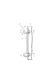
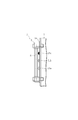
- FIG. 2 is a front view showing the deterioration identifying device
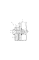
- FIG. 3 is a sectional view taken along the line III-III of FIG. 1 showing the deterioration identifying device
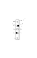
- FIG. 4 is a front view showing a comparison target portion of the deterioration identifying device
- FIG. FIG. In addition, although not shown in figure, the fixing location of the lower side of a sight glass is the same as that of FIG.
- the biofuel degradation identification device 2 is provided at the lower part of one side surface of the fuel tank 1.
- the degradation identification device 2 includes a sight glass 3 (monitoring unit) into which biofuel in the fuel tank 1 is introduced, and a comparison target unit 4 having a color sample for determining degradation.
- the sight glass 3 is made of transparent glass, acrylic resin, or the like, and has a tubular shape that extends in the vertical direction, that is, along the direction of change in the liquid level of the biofuel in the fuel tank 1.
- the sight glass 3 has a display oil passage 5 with a passage extending in the vertical direction inside.
- Fixing bolt holes 3 a are formed at both upper and lower ends of the sight glass 3 toward the fuel tank 1, and these bolt holes 3 a communicate with the upper and lower sides of the display oil passage 5.
- Union bolts 6 are respectively inserted into the upper and lower bolt holes 3a.
- the sight glass 3 is fixed to the fuel tank 1 by a shaft portion 6a of each union bolt 6 that is screwed into a weld nut 7 on the back side through a bolt hole 1a formed on one side surface of the fuel tank 1.
- a T-shaped oil passage 8 is formed in the shaft portion 6 a of each union bolt 6.
- the T-shaped oil passage 8 opens into the fuel tank 1 at the distal end of the shaft portion 6a, and communicates with the display oil passage 5 of the sight glass 3 at the proximal end of the shaft portion 6a. Since the annular oil passage 9 is formed on the entire circumference of the bolt hole 3a, the T-shaped oil passage 8 and the display oil passage 5 are held in communication via the annular oil passage 9 regardless of the bolt rotation position. .
- the display oil passage 5 communicates with the inside of the fuel tank 1 via the T-shaped oil passage 8 of the upper and lower union bolts 6 so that the biofuel stored in the tank 1 is also introduced into the display oil passage 5. It has become.
- the portion fixed by the union bolt 6 is appropriately oil-tightly held by packing to prevent leakage of biofuel to the outside.
- the base plate 10 of the comparison target portion 4 is made of a steel plate and has a rectangular shape extending in the vertical direction.
- the base plate 10 is sandwiched between one side surface of the fuel tank 1 and the sight glass 3 in a state where the shaft portions 6a of the union bolts 6 are respectively inserted into bolt holes 10a penetrating the upper and lower ends thereof. It is fixed. Color samples are individually printed on the left and right sides of the surface of the base plate 10 (site glass 3 side).
- the left and right color samples independently function as a comparison target portion
- the left color sample region is hereinafter referred to as a first comparison target portion 4a toward the drawing
- the right color sample is referred to as the right color sample.
- the region is referred to as a second comparison target portion 4b.
- the entire surface of the base plate 10 is printed in white, and three kinds of color samples are printed on the first and second comparison target portions 4a and 4b, respectively.
- the three color samples of each comparison target part 4a, 4b are set so as to respond stepwise to the color change accompanying the deterioration of the biofuel. That is, biofuel originally has a yellowish hue, and has a characteristic that the lightness gradually decreases with deterioration and changes from a light color to a dark color. Specifically, biofuels change color from light yellow when new to dark brown at the limit of use.
- the first color 11a yellow when it is nearly new
- the third color 11c dark brown corresponding to the use limit
- a color hereinafter referred to as a second color 11b is set, and these color samples 11a to 11c are printed on the base plate 10.
- the biofuel changes color in the order of the first color 11a, the second color 11b, and the third color 11c as it deteriorates.
- the first comparison target section 4a color samples are arranged in order of the first color 11a, the second color 11b, and the third color 11c from the top so as to follow the deterioration direction of the biofuel.
- color samples are arranged in the order of the third color 11c, the second color 11b, and the first color 11a from the top so as to be in the opposite direction to the first comparison target unit 4a.
- the color samples 11a to 11c of the first and second comparison target portions 4a and 4b are located on the back side of the sight glass 3, the color samples 11a to 11c are seen through the biofuel introduced into the display oil passage 5. Is visually recognized, and deterioration can be determined based on the visual recognition state at this time.
- the display of the color samples 11a to 11c is not limited to using printing, and the color samples 11a to 11c may be displayed by painting, for example.
- the background of the color samples 11a to 11c is not limited to white, and may be changed to another color.
- the amount of biofuel stored in the fuel tank 1 fluctuates according to consumption due to operation of the internal combustion engine or replenishment of new fuel.
- the thickness of the water layer formed on the lower side of the biofuel also varies due to condensation in the fuel tank 1. Due to these factors, the liquid level of the biofuel and the liquid level of the water layer in the fuel tank 1 change, and the same liquid level change occurs in the display oil passage 5 of the sight glass 3.
- Biofuel is present in a region between the liquid level of the biofuel and the liquid level of the water layer, and in this region, deterioration can be determined by comparison with the color samples 11a to 11c of the comparison target portions 4a and 4b. .
- the vertical position of the sight glass 3 is set as follows.
- the uppermost position where the liquid level of the water layer can change in the fuel tank 1 Can be specified to some extent.
- the color samples 11a to 11c may not be able to determine deterioration corresponding to the moisture layer.
- the color samples 11a to 11c correspond to the upper air layer of biofuel as the installation position of the sight glass 3 is set upward. As a result, the frequency at which deterioration determination becomes impossible increases.
- the installation position of the sight glass 3 is set above and as much as possible below the maximum upper limit position at which the liquid level of the moisture layer can change.
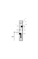
- biofuel degradation identification apparatus 2 Since the liquid level of the biofuel in the fuel tank 1 is normally higher than that of the sight glass 3 and the liquid level of the moisture layer is lower than that of the sight glass 3 due to the position setting of the sight glass 3, FIG. As shown, biofuel is introduced into the display oil passage 5 of the sight glass 3 over the entire vertical direction. As will be described below, deterioration determination of biofuel is performed with reference to any one of the three color samples 11a to 11c of the first and second comparison target portions 4a and 4b. In the case of FIG.
- the principle of deterioration determination by the deterioration identification device 2 of the present embodiment is based on the phenomenon that the color samples 11a to 11c that are visible through the biofuel differ depending on the density change of the biofuel accompanying the deterioration. . That is, when the biofuel is nearly new, only the first color 11a is assimilated to the biofuel and becomes invisible, and the other second and third colors 11b and 11c are visible. When the deterioration of the biofuel proceeds, the second color 11b becomes assimilated to the biofuel and becomes invisible, and when the use limit is reached, the third color 11c becomes assimilated to the biofuel and becomes invisible.
- the deterioration identifying device 2 of the present embodiment includes a sight glass 3 for introducing biofuel in the fuel tank 1 into the inside, and first and second comparison target portions 4a and 4b having color samples 11a to 11c. It has a simple structure and does not require any sensors or processing circuits as in the techniques of Patent Documents 1 and 2. Therefore, it is possible to implement with a simple and inexpensive system, and since it is simple, it has an excellent effect that there is no risk of failure and high reliability can be realized. On the other hand, as is clear from the above description, the determination based on the third color 11c corresponding to the use limit is particularly important as the determination of biofuel deterioration compared to the determination based on the first color 11a and the second color 11b. It is.
- the fuel level in the display oil passage 5 also decreases as shown in FIG. 7 as the level of the biofuel in the fuel tank 1 decreases. Is limited downward.
- the third color 11c is located above the fuel level, for example, as in the second comparison target portion 4b, it is not possible to determine the critical use limit.
- the water level in the display oil passage 5 rises as shown in FIG. 8 as the water level in the fuel tank 1 rises. The area is restricted upward.
- the third color 11c is positioned below the water layer liquid level, for example, as in the first comparison target portion 4a, it is impossible to determine the critical use limit.
- the arrangement of the color samples 11a to 11c of the first and second comparison target portions 4a and 4b is reversed as described above.
- the use limit of the biofuel can be determined.
- the biofuel or moisture layer in the fuel tank 1 It is possible to determine the deterioration of biofuel in more situations without being affected by the liquid level fluctuation. Since the use limit of a particularly important biofuel can be determined, the biofuel can be replaced more appropriately.
- the sight glass 3 since the sight glass 3 is installed above the uppermost position of the liquid level of the moisture layer in the fuel tank 1, it is necessary to drain water when the moisture layer is visually recognized in the display oil passage 5. means. Therefore, the sight glass 3 of the degradation identification device 2 can be used to determine whether or not to drain water. Therefore, there is an advantage of promoting appropriate drainage.
- the color samples 11a to 11c of the first and second comparison target portions 4a and 4b are arranged on the back side of the sight glass 3, and the color sample is seen through the biofuel in the display oil passage 5.
- the principle of determining deterioration by visually recognizing 11a to 11c is adopted, it is not limited to this.
- the color samples 11a to 11c of the first and second comparison target portions 4a and 4b are arranged adjacent to the display oil passage 5, and the biofuel in the display oil passage 5 and the color samples 11a to 11c are arranged. You may make it compare the color (lightness) with.
- the color samples 11a to 11c of the comparison target portions 4a and 4b project from the left and right with the sight glass 3 as the center, and are visible from the front. If the original color of the biofuel can be visually recognized from the outside front by coloring the color sample side) white, the color samples 11a to 11c of the comparison target portions 4a and 4b are placed on the left and right sides of the biofuel in the display oil passage 5. Can be next to each other. Then, it is only necessary to select the same color as the biofuel from the three types of color samples 11a to 11c and determine the deterioration. Although not redundantly explained, the same effect as the above embodiment can be obtained even in this case. be able to.
- the color samples 11a to 11c are displayed on the base plate 10 by printing or painting.
- the transparent capsules 21a to 21c in which actually deteriorated biofuel is sealed are colored. It may be used as a sample.
- transparent capsules 21 a to 21 c are arranged on the upper, middle and lower stages of the base plate 10, respectively, and the inside of each transparent capsule 21 a to 21 c is partitioned at the center in the left-right direction. ing.
- Degraded biofuels corresponding to the first color 11a, the second color 11b, and the third color 11c are sealed from the upper side on the left side in each of the transparent capsules 21a to 21c, and on the right side in each capsule 21a to 21c, From above, degraded biofuel corresponding to the third color 11c, the second color 11b, and the first color 11a is sealed.
- the deterioration biofuel in each of the transparent capsules 21a to 21c can be visually recognized through the biofuel in the display oil passage 5, and the back of the sight glass 3 is colored white. It is possible to determine the deterioration by comparing the colors of the biofuels in the transparent capsules 21a to 21c next to the biofuel in the display oil passage 5 adjacent to each other and comparing the colors. Therefore, not only the same effect as the above-described embodiment can be obtained, but also more accurate deterioration determination can be realized by using the actual deteriorated biofuel as a color sample.
- the biofuel, the lubricating oil, the hydraulic oil deterioration identification device 2 and the fuel tank 1 are embodied in the hydraulic excavator.
- the liquid subjected to the deterioration determination is not limited thereto.
- the configuration of the sight glass 3 and the comparison target portions 4a and 4b is not limited to the above embodiment.
- the shape of the sight glass 3 is changed or the number of the color samples 11a to 11c and 21a to 21c is increased or decreased. Or you may.
- Fuel tank liquid storage tank
- Property identification device deterioration identification device
- Sight glass observation window
- 4a 1st comparison object part
- 4b 2nd comparison object part 11a-11c
- Color sample 21a-21c Transparent capsule (color sample)
Landscapes
- Chemical & Material Sciences (AREA)
- Physics & Mathematics (AREA)
- Life Sciences & Earth Sciences (AREA)
- Health & Medical Sciences (AREA)
- General Physics & Mathematics (AREA)
- Engineering & Computer Science (AREA)
- General Health & Medical Sciences (AREA)
- Pathology (AREA)
- Immunology (AREA)
- Biochemistry (AREA)
- Analytical Chemistry (AREA)
- Spectroscopy & Molecular Physics (AREA)
- Chemical Kinetics & Catalysis (AREA)
- Food Science & Technology (AREA)
- Medicinal Chemistry (AREA)
- Plasma & Fusion (AREA)
- General Chemical & Material Sciences (AREA)
- Oil, Petroleum & Natural Gas (AREA)
- Combustion & Propulsion (AREA)
- Mechanical Engineering (AREA)
- General Engineering & Computer Science (AREA)
- Investigating Or Analysing Materials By The Use Of Chemical Reactions (AREA)
- Investigating Or Analyzing Non-Biological Materials By The Use Of Chemical Means (AREA)
- Investigating Or Analysing Materials By Optical Means (AREA)
- Combined Controls Of Internal Combustion Engines (AREA)
- Spectrometry And Color Measurement (AREA)
Abstract
Priority Applications (4)
| Application Number | Priority Date | Filing Date | Title |
|---|---|---|---|
| KR1020137021656A KR20140004179A (ko) | 2011-02-18 | 2012-02-06 | 액체 성상 식별 장치, 및 그 장치를 장착한 액체 저장 탱크 |
| DE112012000904T DE112012000904T5 (de) | 2011-02-18 | 2012-02-06 | Flüssigkeitsqualitäts-Prüfvorrichtung und mit der Vorrichtung versehener FIiissigkeitsspeichertank |
| US13/984,993 US9046502B2 (en) | 2011-02-18 | 2012-02-06 | Liquid quality checking device and liquid storage tank provided with the device |
| CN2012800093062A CN103380365A (zh) | 2011-02-18 | 2012-02-06 | 液体性状识别装置以及安装了该装置的液体贮藏罐 |
Applications Claiming Priority (2)
| Application Number | Priority Date | Filing Date | Title |
|---|---|---|---|
| JP2011-033088 | 2011-02-18 | ||
| JP2011033088A JP5481410B2 (ja) | 2011-02-18 | 2011-02-18 | 液体性状識別装置、及び同装置を取り付けた液体貯蔵タンク |
Publications (1)
| Publication Number | Publication Date |
|---|---|
| WO2012111469A1 true WO2012111469A1 (fr) | 2012-08-23 |
Family
ID=46672397
Family Applications (1)
| Application Number | Title | Priority Date | Filing Date |
|---|---|---|---|
| PCT/JP2012/052630 Ceased WO2012111469A1 (fr) | 2011-02-18 | 2012-02-06 | Dispositif de vérification de l'état d'un liquide et cuve pour liquide équipée dudit dispositif |
Country Status (6)
| Country | Link |
|---|---|
| US (1) | US9046502B2 (fr) |
| JP (1) | JP5481410B2 (fr) |
| KR (1) | KR20140004179A (fr) |
| CN (1) | CN103380365A (fr) |
| DE (1) | DE112012000904T5 (fr) |
| WO (1) | WO2012111469A1 (fr) |
Families Citing this family (7)
| Publication number | Priority date | Publication date | Assignee | Title |
|---|---|---|---|---|
| JP5566318B2 (ja) * | 2011-02-23 | 2014-08-06 | 日立建機株式会社 | 建設機械の作動油タンク |
| EP3503617B1 (fr) | 2012-08-03 | 2020-07-01 | Sun Patent Trust | Dispositif de terminal de communication sans fil, dispositif de base de communication sans fil et procédé de génération de csi |
| EP3178685B1 (fr) * | 2014-10-30 | 2021-09-22 | Mitsubishi Jidosha Kogyo Kabushiki Kaisha | Dispositif d'affichage de véhicule hybride |
| JP6932185B2 (ja) * | 2017-04-28 | 2021-09-08 | 株式会社小松製作所 | 油の状態検出装置、作業機械、管理システム、及び油の状態検出方法 |
| US10775312B2 (en) * | 2017-06-15 | 2020-09-15 | Tesfa-Michael Tekleab | Instantaneous and time-lapse fluid-flow contaminant indicator |
| JP6817984B2 (ja) * | 2018-06-29 | 2021-01-20 | 日立ジョンソンコントロールズ空調株式会社 | 冷凍機油劣化判定システム |
| JP6954405B2 (ja) * | 2019-05-16 | 2021-10-27 | ダイキン工業株式会社 | 液体センサ及び油圧ユニット |
Citations (5)
| Publication number | Priority date | Publication date | Assignee | Title |
|---|---|---|---|---|
| JPS63135153U (fr) * | 1987-02-27 | 1988-09-05 | ||
| JPS6410658U (fr) * | 1987-07-08 | 1989-01-20 | ||
| JP2008261812A (ja) * | 2007-04-13 | 2008-10-30 | Sumitomo (Shi) Construction Machinery Manufacturing Co Ltd | 建設機械の燃料判別装置 |
| JP2009235967A (ja) * | 2008-03-26 | 2009-10-15 | Toyota Motor Corp | バイオ燃料劣化判定装置 |
| JP2010501843A (ja) * | 2006-08-21 | 2010-01-21 | エスペートロワアッシュ | 燃料の劣化に追随して車両の駆動列の構成要素の安全性を確保する方法 |
Family Cites Families (21)
| Publication number | Priority date | Publication date | Assignee | Title |
|---|---|---|---|---|
| US1537519A (en) * | 1924-12-05 | 1925-05-12 | Yablick Max | Indicating gas-mask canister |
| US3585963A (en) * | 1969-06-18 | 1971-06-22 | Ite Imperial Corp | Fluid indicator |
| US4894342A (en) * | 1986-05-12 | 1990-01-16 | C. D. Medical, Inc. | Bioreactor system |
| US5417204A (en) * | 1993-09-01 | 1995-05-23 | Robert H. Kessler | Scuba air contamination detector |
| CN2344309Y (zh) | 1998-08-13 | 1999-10-20 | 王文革 | 带有可视窗口的罐、盒体 |
| JP3525757B2 (ja) * | 1998-09-18 | 2004-05-10 | 株式会社日立製作所 | 化学分析装置 |
| US20030060984A1 (en) * | 1999-03-19 | 2003-03-27 | Hitachi, Ltd. | Automobile oil deterioration diagnosing apparatus |
| DE19938010A1 (de) * | 1999-08-11 | 2001-02-15 | Bsh Bosch Siemens Hausgeraete | Verfahren zur Steuerung, Regelung und Dokumentation eines Reinigungsvorganges |
| DE60223956T3 (de) * | 2001-03-14 | 2011-05-19 | Hitachi Information & Control Solutions, Ltd., Hitachi | Untersuchungsgerät und System zur Untersuchung von Fremdkörpern in mit Flüssigkeit gefüllten Behältern |
| DE10119932A1 (de) * | 2001-04-23 | 2002-10-31 | Mahle Filtersysteme Gmbh | Transmissionssensor |
| US6543493B2 (en) * | 2001-07-13 | 2003-04-08 | L'air Liquide - Societe'anonyme A' Directoire Et Conseil De Surveillance Pour L'etude Et L'exploitation Des Procedes Georges Claude | Optical monitoring processes and apparatus for combined liquid level sensing and quality control |
| US8372016B2 (en) * | 2002-04-19 | 2013-02-12 | Sanofi-Aventis Deutschland Gmbh | Method and apparatus for body fluid sampling and analyte sensing |
| US7919324B2 (en) | 2002-05-14 | 2011-04-05 | Orit Marom-Albeck | Liquid tester |
| US20040115818A1 (en) * | 2002-12-16 | 2004-06-17 | Puri Pushpinder Singh | Leak detection by reactions at the leak site |
| EP1628567B1 (fr) * | 2003-05-30 | 2010-08-04 | Pelikan Technologies Inc. | Procede et appareil pour injection de fluide |
| US20050042136A1 (en) * | 2003-08-18 | 2005-02-24 | Marganski Paul J. | Colorimetric gas detector and windowed process chamber |
| CN2852115Y (zh) | 2005-08-05 | 2006-12-27 | 艾康生物技术(杭州)有限公司 | 用于样品分析的装置 |
| CN200965519Y (zh) | 2006-12-21 | 2007-10-24 | 何林 | 目测比色卡 |
| JP4483922B2 (ja) | 2007-09-26 | 2010-06-16 | トヨタ自動車株式会社 | 内燃機関の燃料劣化検出装置 |
| BR112012017537A2 (pt) * | 2010-01-19 | 2017-10-03 | Koninklijke Philips Eletronics N V | Aparelho para detectar a qualidade de um liquido, aparelho de purificação por eltravioleta e método para detectar a qualidade de um liquido |
| JP2012098235A (ja) * | 2010-11-05 | 2012-05-24 | Hitachi Appliances Inc | 液質検査器具および液質検査方法 |
-
2011
- 2011-02-18 JP JP2011033088A patent/JP5481410B2/ja not_active Expired - Fee Related
-
2012
- 2012-02-06 US US13/984,993 patent/US9046502B2/en not_active Expired - Fee Related
- 2012-02-06 KR KR1020137021656A patent/KR20140004179A/ko not_active Withdrawn
- 2012-02-06 DE DE112012000904T patent/DE112012000904T5/de not_active Withdrawn
- 2012-02-06 WO PCT/JP2012/052630 patent/WO2012111469A1/fr not_active Ceased
- 2012-02-06 CN CN2012800093062A patent/CN103380365A/zh active Pending
Patent Citations (5)
| Publication number | Priority date | Publication date | Assignee | Title |
|---|---|---|---|---|
| JPS63135153U (fr) * | 1987-02-27 | 1988-09-05 | ||
| JPS6410658U (fr) * | 1987-07-08 | 1989-01-20 | ||
| JP2010501843A (ja) * | 2006-08-21 | 2010-01-21 | エスペートロワアッシュ | 燃料の劣化に追随して車両の駆動列の構成要素の安全性を確保する方法 |
| JP2008261812A (ja) * | 2007-04-13 | 2008-10-30 | Sumitomo (Shi) Construction Machinery Manufacturing Co Ltd | 建設機械の燃料判別装置 |
| JP2009235967A (ja) * | 2008-03-26 | 2009-10-15 | Toyota Motor Corp | バイオ燃料劣化判定装置 |
Also Published As
| Publication number | Publication date |
|---|---|
| US9046502B2 (en) | 2015-06-02 |
| CN103380365A (zh) | 2013-10-30 |
| US20130312497A1 (en) | 2013-11-28 |
| DE112012000904T5 (de) | 2013-11-21 |
| JP5481410B2 (ja) | 2014-04-23 |
| KR20140004179A (ko) | 2014-01-10 |
| JP2012173036A (ja) | 2012-09-10 |
Similar Documents
| Publication | Publication Date | Title |
|---|---|---|
| WO2012111469A1 (fr) | Dispositif de vérification de l'état d'un liquide et cuve pour liquide équipée dudit dispositif | |
| US8261603B2 (en) | Misfire detection apparatus for internal combustion engine | |
| EP2556231B1 (fr) | Dispositif et procédé de diagnostic utilisant un capteur de pression dans un cylindre pour moteur à combustion interne | |
| KR101580449B1 (ko) | 커먼 레일 분사 시스템에서 레일 압력 센서의 에러 작용 및 특히 드리프트를 식별하기 위한 방법 | |
| JP4552898B2 (ja) | 筒内圧センサの異常判定装置 | |
| WO2012009718A1 (fr) | Techniques de détection d'anomalies et permettant d'apporter une réponse à ces dernières | |
| JP2012173036A5 (fr) | ||
| CN108361138A (zh) | 高压共轨管限流阀诊断检测方法及装置 | |
| SE532523C2 (sv) | Metod och system för diagnostisering av gasläckage i ett gasdrivet fordon | |
| JPWO2011111164A1 (ja) | 内燃機関の制御装置 | |
| KR100959214B1 (ko) | 내연 기관의 실화 검출 장치 | |
| JPWO2012090316A1 (ja) | 内燃機関の異常検出装置 | |
| JP2010145107A (ja) | 光学式オイル診断装置ならびに内燃機関の制御装置 | |
| US10794315B2 (en) | Method for diagnosing the operation of a motor vehicle diesel engine injector | |
| KR20130133947A (ko) | 밸브리프트 가변 제어 시스템에서의 밸브 리프트 진단 방법 및 장치 | |
| US12516644B2 (en) | Pressure drop analysis strategy | |
| JP5603825B2 (ja) | 空燃比センサの診断装置 | |
| JP2012241677A (ja) | インジェクタ噴射タイミング補正・診断方法及びコモンレール式燃料噴射制御装置 | |
| JP7206788B2 (ja) | 内燃機関の自動停止制御装置 | |
| KR20030089576A (ko) | 연료 증발가스의 누기영역을 진단하는 장치 및 방법 | |
| KR100345144B1 (ko) | 커먼 레일 디젤 엔진의 연료 누유 감지방법 | |
| KR20010068554A (ko) | 차량 엔진의 고장상태를 진단하는 장치 | |
| JPH0648227B2 (ja) | 液圧回路の液漏れチェック方法 | |
| JP2006264540A (ja) | 異常検出装置、異常情報出力装置、異常情報出力方法、車両制御装置および車両制御方法 | |
| JP4225159B2 (ja) | 潤滑油循環経路検査装置およびその方法 |
Legal Events
| Date | Code | Title | Description |
|---|---|---|---|
| 121 | Ep: the epo has been informed by wipo that ep was designated in this application |
Ref document number: 12747820 Country of ref document: EP Kind code of ref document: A1 |
|
| WWE | Wipo information: entry into national phase |
Ref document number: 13984993 Country of ref document: US |
|
| ENP | Entry into the national phase |
Ref document number: 20137021656 Country of ref document: KR Kind code of ref document: A |
|
| WWE | Wipo information: entry into national phase |
Ref document number: 112012000904 Country of ref document: DE Ref document number: 1120120009045 Country of ref document: DE |
|
| 122 | Ep: pct application non-entry in european phase |
Ref document number: 12747820 Country of ref document: EP Kind code of ref document: A1 |