WO2012111561A1 - Processus de fabrication d'un carter et pompe à vide - Google Patents
Processus de fabrication d'un carter et pompe à vide Download PDFInfo
- Publication number
- WO2012111561A1 WO2012111561A1 PCT/JP2012/053138 JP2012053138W WO2012111561A1 WO 2012111561 A1 WO2012111561 A1 WO 2012111561A1 JP 2012053138 W JP2012053138 W JP 2012053138W WO 2012111561 A1 WO2012111561 A1 WO 2012111561A1
- Authority
- WO
- WIPO (PCT)
- Prior art keywords
- cylinder liner
- casing
- cylinder
- hole
- peripheral surface
- Prior art date
- Legal status (The legal status is an assumption and is not a legal conclusion. Google has not performed a legal analysis and makes no representation as to the accuracy of the status listed.)
- Ceased
Links
Images



Classifications
-
- F—MECHANICAL ENGINEERING; LIGHTING; HEATING; WEAPONS; BLASTING
- F04—POSITIVE - DISPLACEMENT MACHINES FOR LIQUIDS; PUMPS FOR LIQUIDS OR ELASTIC FLUIDS
- F04C—ROTARY-PISTON, OR OSCILLATING-PISTON, POSITIVE-DISPLACEMENT MACHINES FOR LIQUIDS; ROTARY-PISTON, OR OSCILLATING-PISTON, POSITIVE-DISPLACEMENT PUMPS
- F04C29/00—Component parts, details or accessories of pumps or pumping installations, not provided for in groups F04C18/00 - F04C28/00
-
- F—MECHANICAL ENGINEERING; LIGHTING; HEATING; WEAPONS; BLASTING
- F01—MACHINES OR ENGINES IN GENERAL; ENGINE PLANTS IN GENERAL; STEAM ENGINES
- F01C—ROTARY-PISTON OR OSCILLATING-PISTON MACHINES OR ENGINES
- F01C21/00—Component parts, details or accessories not provided for in groups F01C1/00 - F01C20/00
- F01C21/10—Outer members for co-operation with rotary pistons; Casings
-
- F—MECHANICAL ENGINEERING; LIGHTING; HEATING; WEAPONS; BLASTING
- F04—POSITIVE - DISPLACEMENT MACHINES FOR LIQUIDS; PUMPS FOR LIQUIDS OR ELASTIC FLUIDS
- F04C—ROTARY-PISTON, OR OSCILLATING-PISTON, POSITIVE-DISPLACEMENT MACHINES FOR LIQUIDS; ROTARY-PISTON, OR OSCILLATING-PISTON, POSITIVE-DISPLACEMENT PUMPS
- F04C18/00—Rotary-piston pumps specially adapted for elastic fluids
- F04C18/30—Rotary-piston pumps specially adapted for elastic fluids having the characteristics covered by two or more of groups F04C18/02, F04C18/08, F04C18/22, F04C18/24, F04C18/48, or having the characteristics covered by one of these groups together with some other type of movement between co-operating members
- F04C18/34—Rotary-piston pumps specially adapted for elastic fluids having the characteristics covered by two or more of groups F04C18/02, F04C18/08, F04C18/22, F04C18/24, F04C18/48, or having the characteristics covered by one of these groups together with some other type of movement between co-operating members having the movement defined in group F04C18/08 or F04C18/22 and relative reciprocation between the co-operating members
- F04C18/344—Rotary-piston pumps specially adapted for elastic fluids having the characteristics covered by two or more of groups F04C18/02, F04C18/08, F04C18/22, F04C18/24, F04C18/48, or having the characteristics covered by one of these groups together with some other type of movement between co-operating members having the movement defined in group F04C18/08 or F04C18/22 and relative reciprocation between the co-operating members with vanes reciprocating with respect to the inner member
- F04C18/3441—Rotary-piston pumps specially adapted for elastic fluids having the characteristics covered by two or more of groups F04C18/02, F04C18/08, F04C18/22, F04C18/24, F04C18/48, or having the characteristics covered by one of these groups together with some other type of movement between co-operating members having the movement defined in group F04C18/08 or F04C18/22 and relative reciprocation between the co-operating members with vanes reciprocating with respect to the inner member the inner and outer member being in contact along one line or continuous surface substantially parallel to the axis of rotation
- F04C18/3442—Rotary-piston pumps specially adapted for elastic fluids having the characteristics covered by two or more of groups F04C18/02, F04C18/08, F04C18/22, F04C18/24, F04C18/48, or having the characteristics covered by one of these groups together with some other type of movement between co-operating members having the movement defined in group F04C18/08 or F04C18/22 and relative reciprocation between the co-operating members with vanes reciprocating with respect to the inner member the inner and outer member being in contact along one line or continuous surface substantially parallel to the axis of rotation the surfaces of the inner and outer member, forming the inlet and outlet opening
-
- F—MECHANICAL ENGINEERING; LIGHTING; HEATING; WEAPONS; BLASTING
- F04—POSITIVE - DISPLACEMENT MACHINES FOR LIQUIDS; PUMPS FOR LIQUIDS OR ELASTIC FLUIDS
- F04C—ROTARY-PISTON, OR OSCILLATING-PISTON, POSITIVE-DISPLACEMENT MACHINES FOR LIQUIDS; ROTARY-PISTON, OR OSCILLATING-PISTON, POSITIVE-DISPLACEMENT PUMPS
- F04C2230/00—Manufacture
- F04C2230/20—Manufacture essentially without removing material
- F04C2230/21—Manufacture essentially without removing material by casting
-
- F—MECHANICAL ENGINEERING; LIGHTING; HEATING; WEAPONS; BLASTING
- F04—POSITIVE - DISPLACEMENT MACHINES FOR LIQUIDS; PUMPS FOR LIQUIDS OR ELASTIC FLUIDS
- F04C—ROTARY-PISTON, OR OSCILLATING-PISTON, POSITIVE-DISPLACEMENT MACHINES FOR LIQUIDS; ROTARY-PISTON, OR OSCILLATING-PISTON, POSITIVE-DISPLACEMENT PUMPS
- F04C2230/00—Manufacture
- F04C2230/90—Improving properties of machine parts
- F04C2230/91—Coating
-
- F—MECHANICAL ENGINEERING; LIGHTING; HEATING; WEAPONS; BLASTING
- F04—POSITIVE - DISPLACEMENT MACHINES FOR LIQUIDS; PUMPS FOR LIQUIDS OR ELASTIC FLUIDS
- F04C—ROTARY-PISTON, OR OSCILLATING-PISTON, POSITIVE-DISPLACEMENT MACHINES FOR LIQUIDS; ROTARY-PISTON, OR OSCILLATING-PISTON, POSITIVE-DISPLACEMENT PUMPS
- F04C2240/00—Components
- F04C2240/80—Other components
- F04C2240/802—Liners
-
- F—MECHANICAL ENGINEERING; LIGHTING; HEATING; WEAPONS; BLASTING
- F04—POSITIVE - DISPLACEMENT MACHINES FOR LIQUIDS; PUMPS FOR LIQUIDS OR ELASTIC FLUIDS
- F04C—ROTARY-PISTON, OR OSCILLATING-PISTON, POSITIVE-DISPLACEMENT MACHINES FOR LIQUIDS; ROTARY-PISTON, OR OSCILLATING-PISTON, POSITIVE-DISPLACEMENT PUMPS
- F04C2250/00—Geometry
- F04C2250/10—Geometry of the inlet or outlet
-
- F—MECHANICAL ENGINEERING; LIGHTING; HEATING; WEAPONS; BLASTING
- F04—POSITIVE - DISPLACEMENT MACHINES FOR LIQUIDS; PUMPS FOR LIQUIDS OR ELASTIC FLUIDS
- F04C—ROTARY-PISTON, OR OSCILLATING-PISTON, POSITIVE-DISPLACEMENT MACHINES FOR LIQUIDS; ROTARY-PISTON, OR OSCILLATING-PISTON, POSITIVE-DISPLACEMENT PUMPS
- F04C25/00—Adaptations of pumps for special use of pumps for elastic fluids
- F04C25/02—Adaptations of pumps for special use of pumps for elastic fluids for producing high vacuum
Definitions
- the present invention relates to a method for manufacturing a casing including a cylinder chamber in which a rotary compression element driven by a driving machine slides, and a vacuum pump including the casing.
- a vacuum pump having a casing attached to a driving machine such as an electric motor and a rotary compression element that is rotated by the driving machine in a cylinder chamber of the casing is known.
- a vacuum can be obtained by driving a rotary compression element in a cylinder chamber by a driving machine.
- a vacuum is installed in an engine room of an automobile to operate a brake booster. It is used for generating (see, for example, Patent Document 1).
- this type of vacuum pump is required to be reduced in size because the installation space cannot be made large.
- a cylinder liner that forms a cylinder chamber in the casing body, the rotation axis direction of the casing It is envisaged that the dimensions will be reduced.
- a cylinder liner is manufactured in which a peripheral wall is processed with an intake hole and an exhaust hole communicating with the cylinder chamber, and an inner surface of the cylinder chamber is subjected to a surface hardening process such as an electroless plating process. The liner was press-fitted into the hole in the casing body.
- An object of the present invention is to provide a casing manufacturing method and a vacuum pump provided with the casing that are reduced in the axial direction and reduce the number of work steps.
- the present invention provides a casing manufacturing method including a cylinder chamber in which a rotary compression element driven by a driving machine slides, wherein a cylinder liner forming the cylinder chamber is disposed in a mold, and the casing Casting using a molten metal for forming a main body, casting the cylinder liner integrally, and processing an intake hole and an exhaust hole that penetrate the cylinder liner and the casing body integrally and communicate with the cylinder chamber And.
- the cylinder liner and the casing are processed in order to process the intake hole and the exhaust hole that penetrate the cylinder liner and the casing body and communicate with the cylinder chamber.
- the adjustment work of the hole position with the main body and the additional work of the casing main body are not necessary, and the number of work man-hours during manufacturing can be reduced.
- the casing can be reduced in size in the axial direction.
- the method includes a step of coating the inner peripheral surface of the cylinder liner in which the intake hole and the exhaust hole are processed with a metal harder than the cylinder liner. According to this configuration, a sliding surface having high hardness can be easily formed even in a casing in which a cylinder liner is integrally cast in the casing body.
- a step of forming a means for preventing rotation and removal of the cylinder liner on the outer peripheral surface of the cylinder liner prior to the step of casting the cylinder liner, there is provided a step of forming a means for preventing rotation and removal of the cylinder liner on the outer peripheral surface of the cylinder liner.
- the means for preventing rotation and removal is formed in advance on the outer peripheral surface of the cylinder liner.
- the cylinder liner can be prevented from rotating and coming off more easily than a press-fitted one.
- a spiral groove is formed on the outer peripheral surface of the cylinder liner. According to this configuration, it is possible to easily create a cylinder liner that prevents rotation and disconnection.
- the present invention also provides a vacuum pump including a casing attached to a driving machine, and a cylinder chamber in which a rotary compression element driven by the driving machine slides.
- the casing is a cast casing body.
- a cylinder liner that is integrally cast into the cylinder chamber and includes an intake hole and an exhaust hole that integrally penetrate the cylinder liner and the casing body and communicate with the cylinder chamber.
- the cylinder liner and the casing are processed in order to process the intake hole and the exhaust hole that penetrate the cylinder liner and the casing body and communicate with the cylinder chamber.
- the adjustment work of the hole position with the main body and the additional work of the casing main body are not necessary, and the number of work man-hours during manufacturing can be reduced.
- the casing can be reduced in size in the axial direction.
- FIG. 1 is a schematic diagram of a brake device using a vacuum pump according to the present embodiment.
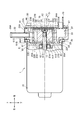
- FIG. 2 is a side partial sectional view of the vacuum pump.
- FIG. 3 is a view of the vacuum pump as viewed from the front side.
- FIG. 4 is a flowchart showing a manufacturing procedure of the casing.
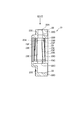
- FIG. 5 is a side partial sectional view of the casing showing a spiral groove formed on the outer peripheral surface of the cylinder liner to prevent rotation and slipping.
- FIG. 1 is a schematic diagram of a brake device 100 using a vacuum pump 1 according to an embodiment of the present invention as a negative pressure source.
- the brake device 100 includes, for example, front brakes 2A and 2B attached to left and right front wheels of a vehicle such as an automobile, and rear brakes 3A and 3B attached to left and right rear wheels.
- Each of these brakes is connected to each other by a master cylinder 4 and a brake pipe 9, and each brake is operated by a hydraulic pressure sent from the master cylinder 4 through the brake pipe 9.
- the brake device 100 includes a brake booster (brake booster) 6 connected to the brake pedal 5, and the vacuum tank 7 and the vacuum pump 1 are connected in series to the brake booster 6 through an air pipe 8. It is connected.
- the brake booster 6 uses the negative pressure in the vacuum tank 7 to boost the pedaling force of the brake pedal 5, and it is sufficient to move the piston (not shown) of the master cylinder 4 with a small pedaling force.
- the braking power can be pulled out.
- the vacuum pump 1 is disposed in the engine room of the vehicle, discharges the air in the vacuum tank 7 to the outside of the vehicle, and puts the vacuum tank 7 in a vacuum state. Note that the range of use of the vacuum pump 1 used in an automobile or the like is, for example, ⁇ 60 kPa to ⁇ 80 kPa.
- FIG. 2 is a side partial sectional view of the vacuum pump 1
- FIG. 3 is a view of the vacuum pump 1 of FIG. 2 as viewed from the front side (right side in the figure).
- FIG. 3 illustrates a state in which members such as the pump cover 24 and the side plate 26 are removed in order to show the configuration of the cylinder chamber S.
- the directions indicated by the arrows at the top of FIGS. 2 and 3 respectively indicate the top, bottom, front, back, left and right of the vacuum pump 1.
- the front-rear direction is also referred to as the axial direction
- the left-right direction is also referred to as the width direction.
- the vacuum pump 1 includes an electric motor (driving machine) 10 and a pump main body 20 that operates using the electric motor 10 as a driving source.
- the electric motor 10 and the pump main body 20 are integrated with each other. In a connected state, it is fixedly supported on a vehicle body such as an automobile.
- the electric motor 10 has an output shaft (rotary shaft) 12 that extends from the approximate center of one end (front end) of the case 11 formed in a substantially cylindrical shape toward the pump body 20 side (front side).
- the output shaft 12 functions as a drive shaft that drives the pump main body 20, and rotates with reference to a rotation center X1 extending in the front-rear direction.
- the front end portion 12A of the output shaft 12 is formed as a spline shaft, and engages with a spline groove 27D formed in a part of a shaft hole 27A penetrating in the axial direction of the rotor 27 of the pump body 20,
- the rotor 27 is connected to the rotor 27 so as to be integrally rotatable.
- the case 11 includes a case main body 60 formed in a bottomed cylindrical shape and a cover body 61 that closes the opening of the case main body 60.
- the case main body 60 is formed by bending the peripheral edge portion 60A outward.
- the cover body 61 includes a disc portion (wall surface) 61A formed with substantially the same diameter as the opening of the case body 60, and a cylindrical portion 61B that is connected to the periphery of the disc portion 61A and fits on the inner peripheral surface of the case body 60.
- a bent portion 61C formed by bending the peripheral edge of the cylindrical portion 61B outward, the disc portion 61A and the cylindrical portion 61B enter the case body 60, and the bent portion 61C
- the case body 60 is fixed in contact with the peripheral edge 60A.
- one end part (front end) of the case 11 is recessed inward in the electric motor 10, and the fitting hole part 63 to which the pump main body 20 is attached by spigot fitting is formed.
- a through hole 61D through which the output shaft 12 passes and an annular bearing holding portion 61E extending inward of the case main body 60 are formed around the through hole 61D at the approximate center of the disc part 61A.
- the outer ring of the bearing 62 that supports the front side of the output shaft 12 is held on the inner peripheral surface 61F of the bearing holding portion 61E.
- the pump body 20 includes a casing body 22 fitted in a fitting hole 63 formed on the front side of the case 11 of the electric motor 10, and a cylinder chamber disposed in the casing body 22.
- the cylinder liner 23 which forms S, and the pump cover 24 which covers the said casing main body 22 from the front side are provided.
- the casing body 22 and the cylinder liner 23 are provided, and the casing 31 of the vacuum pump 1 is configured.
- the casing body 22 is made of, for example, a metal material having high thermal conductivity such as aluminum, and the shape seen from the front side is a substantially rectangular shape that is long in the vertical direction with the rotation center X1 as the center. Is formed.
- a communication hole 22A communicating with the cylinder chamber S provided in the casing main body 22 is formed in the upper portion of the casing main body 22, and a suction nipple 30 is press-fitted into the communication hole 22A.
- the suction nipple 30 is a straight pipe extending upward, and negative pressure air is supplied to one end 30A of the suction nipple 30 from an external device (for example, the vacuum tank 7 (see FIG. 1)).
- a tube or tube for feeding is connected.
- the casing body 22 is formed with a hole 22B based on the axial center X2 extending in the front-rear direction, and a cylinder liner 23 formed in a cylindrical shape is cast into the hole 22B. Specifically, in a state where the cylinder liner 23 is set in the mold, the casing body 22 (casing 31) in which the cylinder liner 23 is integrally cast is cast by pouring the mold into the mold.
- the shaft center X2 is parallel to the rotation center X1 of the output shaft 12 of the electric motor 10 described above and, as shown in FIG.
- the shaft center X2 is eccentric so that the outer peripheral surface 27B of the rotor 27 centered on the rotation center X1 is in contact with the inner peripheral surface 23A of the cylinder liner 23 formed with the shaft center X2 as a reference.
- the cylinder liner 23 is formed of the same metal material as the rotor 27 (in this embodiment, iron), and the inner peripheral surface 23A of the cylinder liner 23 is subjected to a surface hardening process such as hard chrome plating. Thus, the hardness of the inner peripheral surface (sliding surface) 23A is increased.
- the cylinder liner 23 since the cylinder liner 23 can be accommodated within the longitudinal range of the casing body 22 by casting the cylinder liner 23 integrally with the casing body 22, the cylinder liner 23 is used as the casing body.
- the casing body 22 can be reduced in size.
- the casing body 22 is formed of a material having higher thermal conductivity than the rotor 27. According to this, heat generated when the rotor 27 and the vane 28 are rotationally driven can be quickly transmitted to the casing body 22, so that the casing body 22 can sufficiently dissipate heat.
- the cylinder liner 23 is formed with an opening (intake hole) 23B that connects the above-described communication hole (intake hole) 22A of the casing body 22 and the inside of the cylinder chamber S. Air through the suction nipple 30 is communicated with the communication hole 22A. , Are supplied into the cylinder chamber S through the opening 23B. Further, exhaust holes 22 ⁇ / b> C and 23 ⁇ / b> C that pass through the casing body 22 and the cylinder liner 23 and discharge air compressed in the cylinder chamber S are provided at the lower part of the casing body 22 and the cylinder liner 23.
- the communication hole 22A, the opening 23B, and the exhaust holes 22C, 23C are arranged on the same axis with the cylinder chamber S interposed therebetween. It can be formed by a single drilling process.
- a rotor 27 is disposed in the cylinder chamber S.
- the rotor 27 has a columnar shape extending along the rotation center X1 of the electric motor 10, and has a shaft hole 27A through which the output shaft 12 that is a drive shaft of the pump body 20 is inserted, and radial direction from the shaft hole 27A.
- a plurality of guide grooves 27C are provided at equidistant intervals around the shaft hole 27A at intervals in the circumferential direction.
- a part of the shaft hole 27A is formed with a spline groove 27D that engages with a spline shaft provided at the distal end portion 12A of the output shaft 12, so that the rotor 27 and the output shaft 12 are spline-connected. Yes.
- a cylindrical recess 27F having a diameter larger than that of the shaft hole 27A is formed around the shaft hole 27A on the front end surface of the rotor 27, and the tip of the output shaft 12 extends into the recess 27F.
- a push nut 70 is attached to this, and the push nut 70 restricts the rotor 27 from moving toward the tip end side of the output shaft 12.
- the length of the rotor 27 in the front-rear direction is set to be approximately equal to the length of the cylinder chamber S of the cylinder liner 23, that is, the distance between the inner surfaces of the two side plates 25 and 26 facing each other. And the side plates 25 and 26 are substantially closed. Further, as shown in FIG. 3, the outer diameter of the rotor 27 is such that the outer peripheral surface 27B of the rotor 27 maintains a minute clearance with the portion of the inner peripheral surface 23A of the cylinder liner 23 that is located obliquely downward to the right. Is set.
- the inside of the cylinder chamber S partitioned by the side plates 25 and 26 has a crescent shape between the outer peripheral surface 27B of the rotor 27 and the inner peripheral surface 23A of the cylinder liner 23, as shown in FIG. A space is constructed.
- the rotor 27 is provided with a plurality (five in this example) of vanes 28 that divide a crescent-shaped space.
- the vane 28 is formed in a plate shape, and its length in the front-rear direction is set to be approximately equal to the distance between the mutually facing inner surfaces of the two side plates 25, 26, similar to the rotor 27. ing.
- These vanes 28 are arranged so as to be able to protrude and retract from guide grooves 27 ⁇ / b> C provided in the rotor 27.
- Each vane 28 protrudes outward along the guide groove 27 ⁇ / b> C by centrifugal force as the rotor 27 rotates, and a tip of the vane 28 comes into contact with the inner peripheral surface 23 ⁇ / b> A of the cylinder liner 23.
- the crescent-shaped space described above is divided into five compression chambers P surrounded by the two adjacent vanes 28, 28, the outer peripheral surface 27B of the rotor 27, and the inner peripheral surface 23A of the cylinder liner 23. Partitioned.
- These compression chambers P rotate in the same direction as the rotation of the output shaft 12 in the direction of the arrow R of the rotor 27.
- the volume of the compression chamber P increases in the vicinity of the opening 23B, and decreases in the exhaust hole 23C.
- the rotary compression element is configured by including the rotor 27 and the plurality of vanes 28.
- the cylinder liner 23 is cast into the casing body 22 such that the axis X2 of the cylinder liner 23 is eccentrically leftward and upward with respect to the rotation center X1. For this reason, a large space can be secured in the casing body 22 in the direction opposite to the direction in which the cylinder liner 23 is eccentric.
- the exhaust holes 23C and 22C are formed along the peripheral edge of the cylinder liner 23 in this space.
- An expansion chamber 33 communicated with is formed.
- the expansion chamber 33 is formed as a large closed space along the peripheral edge of the cylinder liner 23 from below the cylinder liner 23 to above the output shaft 12, and communicates with an exhaust port 24 ⁇ / b> A formed in the pump cover 24. ing.
- the compressed air that has flowed into the expansion chamber 33 expands and disperses in the expansion chamber 33, collides with the partition walls of the expansion chamber 33, and is irregularly reflected. Thereby, since the sound energy of compressed air is attenuated, noise and vibration during exhaust can be reduced.
- the pump cover 24 is disposed on the front side plate 26 via a wave washer 26A, and is fixed to the casing body 22 with bolts 66. As shown in FIG. 3, a seal groove 22D is formed on the front surface of the casing body 22 so as to surround the cylinder liner 23 and the expansion chamber 33, and an annular seal material 67 (FIG. 2) is disposed in the seal groove 22D. ing.
- the pump cover 24 is provided with an exhaust port 24 ⁇ / b> A at a position corresponding to the expansion chamber 33. This exhaust port 24A is for exhausting the air that has flowed into the expansion chamber 33 to the outside of the machine (outside the vacuum pump 1), and this exhaust port 24A prevents the backflow of air from the outside of the machine into the pump.
- a check valve 29 is attached.
- the vacuum pump 1 is configured by connecting an electric motor 10 and a pump main body 20, and a rotor 27 and a vane 28 connected to the output shaft 12 of the electric motor 10 are disposed in a cylinder liner 23 of the pump main body 20. Slide. For this reason, it is important to assemble the pump body 20 in accordance with the rotation center X1 of the output shaft 12 of the electric motor 10. For this reason, in this embodiment, the electric motor 10 has a fitting hole 63 formed around the rotation center X1 of the output shaft 12 on one end side of the case 11. On the other hand, as shown in FIG. 2, a cylindrical fitting portion 22 ⁇ / b> F projecting rearward around the cylinder chamber S is integrally formed on the back surface of the casing body 22.
- the fitting portion 22 ⁇ / b> F is formed concentrically with the rotation center X ⁇ b> 1 of the output shaft 12 of the electric motor 10, and has an outer diameter that fits in the fitting hole 63 of the electric motor 10. Accordingly, in this configuration, the center position can be easily adjusted by simply fitting the fitting portion 22F of the casing body 22 into the fitting hole portion 63 of the electric motor 10, and the electric motor 10 and the pump body 20 can be aligned. Assembly work can be performed easily. Further, a seal groove 22E is formed around the fitting portion 22F on the back surface of the casing body 22, and an annular seal material 35 is disposed in the seal groove 22E.
- FIG. 4 is a flowchart showing a procedure for manufacturing the casing 31.
- a spiral groove (means for preventing rotation and disconnection) is formed on the outer peripheral surface of the cylinder liner 23 used in the casing 31 (step S1). Specifically, as shown in FIG. 5, a plurality of grooves 23 ⁇ / b> E extending in a spiral shape are formed on the outer peripheral surface 23 ⁇ / b> D of the cylinder liner 23.
- the groove 23E functions as an anchor when the molten metal enters the groove 23E, and prevents the cylinder liner 23 from rotating and coming off.
- the groove 23E is preferably formed by closing the end 23F, but the pitch between the grooves 23E may be changed.
- the spirally extending groove 23E can be easily formed by applying a cutting tool (bite) to the outer peripheral surface 23D of the cylinder liner 23 in a state where the cylinder liner 23 is held by a lathe chuck. Further, the pitch of the groove 23E can be easily changed by adjusting the feed amount of the cylinder liner 23.
- a cutting tool bite
- the pitch of the groove 23E can be easily changed by adjusting the feed amount of the cylinder liner 23.
- an example in which the groove 23E that spirally extends on the outer peripheral surface 23D of the cylinder liner 23 is described is described as an example, but the present invention is not limited thereto.
- the outer peripheral surface 23D of the cylinder liner 23 may be processed to have irregularities such as dimples.
- the casing body 22 is cast with the cylinder liner 23 cast (step S2).
- the cylinder liner 23 is set in a die casting mold (not shown), and molten metal (molten metal) such as aluminum is poured into the mold in this state.
- molten metal molten metal
- the casing body 22 in which the cylinder liner 23 is integrally cast is cast.
- the cylinder liner 23 and the casing body 22 are integrally machined (step S3).
- the communication hole 22A of the casing body 22 as the intake hole and the opening 23B of the cylinder liner 23 are integrally drilled, and the exhaust hole 22C of the casing body 22 and the exhaust hole 23C of the cylinder liner 23 are integrally formed.
- the communication hole 22A, the opening 23B, and the exhaust holes 22C, 23C are arranged on the same axis with the cylinder chamber S interposed therebetween. These can be formed by drilling. In addition, after these hole processing, the deburring which arises around 22 A of communicating holes, the opening 23B, and the exhaust holes 22C and 23C is performed. Since the inner peripheral surface 23A of the cylinder liner 23 functions as a sliding surface on which the rotor 27 and the vane 28 slide, it is necessary to accurately mold the inner diameter of the cylinder liner 23.
- the cylinder liner 23 is cast into the casing main body 22, the cylinder liner 23 is thermally expanded by contact with high-temperature molten metal in the casting process, and is thermally contracted in the cooling process.
- the inner diameter of the cylinder liner 23 may vary from individual to individual. For this reason, by cutting the inner peripheral surface 23A of the cast cylinder liner 23, the inner diameter of the cylinder liner 23 is accurately adjusted to the specified dimension.
- step S4 the surface treatment which coat
- hard chrome plating is applied to the inner peripheral surface 23 ⁇ / b> A of the cylinder liner 23.
- the entire casing main body is immersed in a chrome plating tank and hard chrome plating is applied to the inner peripheral surface 23A.
- the inner peripheral surface 23A is buffed or the like to accurately adjust the inner diameter of the cylinder liner 23 to a specified dimension.
- the cylinder liner 23 is masked (step S5), the surface of the casing body 22 is subjected to trivalent zinc plating (step S6), and the process ends.
- the cylinder liner that forms the cylinder chamber S is formed. 23 is placed in a mold, cast using molten aluminum for forming the casing main body 22, and the cylinder liner 23 is integrally cast, and the cylinder liner 23 and the casing main body 22 are integrally penetrated to enter the cylinder chamber S. And the step of machining the communication hole 22A, the opening 23B, and the exhaust holes 22C and 23C.
- the casing body 22 into which the cylinder liner 23 is integrally cast is integrally penetrated to communicate with the inside of the cylinder chamber S.
- the communication hole 22A, the opening 23B, and the exhaust holes 22C and 23C can be processed. This eliminates the need for adjusting the hole position between the cylinder liner 23 and the casing main body 22 and the additional work of the casing main body 22 that have occurred in the process of press-fitting the cylinder liner. It is possible to reduce the man-hours for manufacturing. Further, since the cylinder liner 23 is cast into the casing body 22 and the casing 31 is manufactured, the casing 31 can be reduced in size in the axial direction.
- a casing in which the cylinder liner 23 is integrally cast into the casing body 22 in order to perform the hard chrome plating process on the inner peripheral surface 23A of the cylinder liner 23 in which the opening 23B and the exhaust hole 23C are processed Even if it is 31, a highly rigid sliding surface can be formed easily.
- the cylinder liner 23 prior to the step of casting the cylinder liner 23, the cylinder liner 23 is provided with a step of forming means for preventing the rotation and removal of the cylinder liner 23 on the outer peripheral surface 23 ⁇ / b> D of the cylinder liner 23. Even if metals having different coefficients of thermal expansion are employed between the casing body 22 and the casing body 22, the structure for preventing the cylinder liner 23 from rotating and coming off can be simplified as compared with the case where the cylinder liner is press-fitted.
- the spiral groove portion 23E is formed on the outer peripheral surface 23D of the cylinder liner 23, so that the cylinder liner 23 that prevents rotation and disconnection is easily created. be able to.
- the vacuum pump 1 including the casing 31 attached to the electric motor 10 and including the cylinder chamber S in which the rotor 27 and the vane 28 driven by the electric motor 10 slide in the casing 31.
- the casing 31 includes a cylinder liner 23 that is integrally cast into the cast casing body 22 to form the cylinder chamber S.
- the casing 31 integrally penetrates the cylinder liner 23 and the casing body 22 and communicates with the cylinder chamber S. Since the communication hole 22A, the opening 23B, and the exhaust holes 22C and 23C are provided, it is possible to reduce the size in the direction of the rotation axis, and to reduce the work man-hours at the time of manufacture compared to the case where the cylinder liner is press-fitted. it can.
- Vacuum pump 10 Electric motor (driving machine) 12 Output shaft (rotary shaft) 22 Casing body 22A Communication hole (intake hole) 22B hole 22C exhaust hole 23 cylinder liner 23A inner peripheral surface 23B opening (intake hole) 23C Exhaust hole 23D Outer peripheral surface 23E Groove (helical groove) 23F End 24 Pump cover 27 Rotor (rotary compression element) 28 Vane (Rotary compression element) 31 Casing S Cylinder chamber
Landscapes
- Engineering & Computer Science (AREA)
- Mechanical Engineering (AREA)
- General Engineering & Computer Science (AREA)
- Applications Or Details Of Rotary Compressors (AREA)
- Rotary Pumps (AREA)
Abstract
La présente invention a pour objet d'empêcher l'endommagement d'un rotor et d'une plaque latérale en employant une constitution simple pour empêcher ainsi la détérioration de la durabilité d'une pompe à vide.
Le processus comporte : une étape consistant à mettre en place une chemise de cylindre qui constitue une chambre de cylindre dans un moule, à mouler un métal fondu pour former un corps principal de carter et à couler une chemise de cylindre de manière intégrée (étape S2) ; et une étape consistant à perforer la chemise de cylindre et le corps principal de carter de manière intégrée pour réaliser un trou d'entrée d'air et un trou de sortie d'air, qui sont tous deux mis en communication avec l'intérieur de la chambre de cylindre (étape S3).
Priority Applications (3)
| Application Number | Priority Date | Filing Date | Title |
|---|---|---|---|
| US13/984,165 US9347447B2 (en) | 2011-02-14 | 2012-02-10 | Process for manufacturing casing, and vacuum pump |
| CN201280008904.8A CN103477081B (zh) | 2011-02-14 | 2012-02-10 | 机壳的制造方法及真空泵 |
| EP12747506.9A EP2677173B1 (fr) | 2011-02-14 | 2012-02-10 | Processus de fabrication d'un carter et pompe à vide |
Applications Claiming Priority (2)
| Application Number | Priority Date | Filing Date | Title |
|---|---|---|---|
| JP2011028481A JP2012167590A (ja) | 2011-02-14 | 2011-02-14 | ケーシングの製造方法及び真空ポンプ |
| JP2011-028481 | 2011-02-14 |
Publications (1)
| Publication Number | Publication Date |
|---|---|
| WO2012111561A1 true WO2012111561A1 (fr) | 2012-08-23 |
Family
ID=46672486
Family Applications (1)
| Application Number | Title | Priority Date | Filing Date |
|---|---|---|---|
| PCT/JP2012/053138 Ceased WO2012111561A1 (fr) | 2011-02-14 | 2012-02-10 | Processus de fabrication d'un carter et pompe à vide |
Country Status (4)
| Country | Link |
|---|---|
| US (1) | US9347447B2 (fr) |
| EP (1) | EP2677173B1 (fr) |
| JP (1) | JP2012167590A (fr) |
| WO (1) | WO2012111561A1 (fr) |
Citations (9)
| Publication number | Priority date | Publication date | Assignee | Title |
|---|---|---|---|---|
| JPS6318195A (ja) * | 1986-07-10 | 1988-01-26 | Toyota Autom Loom Works Ltd | スライドベ−ン型回転圧縮機におけるシリンダブロツクの製造方法 |
| JPH01105065U (fr) * | 1987-12-29 | 1989-07-14 | ||
| JP2001170755A (ja) * | 1999-12-15 | 2001-06-26 | Tp Kogyo Kk | 鋳ぐるみ用鋳鉄部材、それを用いた鋳ぐるみ製品、及び鋳ぐるみ用鋳鉄部材の製造方法 |
| JP2003222090A (ja) | 2002-01-31 | 2003-08-08 | Denso Corp | ベーン型真空ポンプ |
| WO2004111460A1 (fr) * | 2003-06-11 | 2004-12-23 | Matsushita Electric Industrial Co., Ltd. | Pompe pneumatique rotative a palettes |
| JP2008196346A (ja) * | 2007-02-09 | 2008-08-28 | Mazda Motor Corp | 摺動部材及びその製造方法 |
| JP2008545096A (ja) * | 2005-07-07 | 2008-12-11 | エーリコン ライボルト ヴァキューム ゲゼルシャフト ミット ベシュレンクテル ハフツング | 真空ベーンポンプ |
| JP2009091973A (ja) * | 2007-10-09 | 2009-04-30 | Denso Corp | 真空ポンプ |
| JP2010059909A (ja) * | 2008-09-05 | 2010-03-18 | Fuji Heavy Ind Ltd | シリンダライナ、シリンダブロック及びシリンダライナの製造方法 |
Family Cites Families (5)
| Publication number | Priority date | Publication date | Assignee | Title |
|---|---|---|---|---|
| US5571005A (en) * | 1995-06-07 | 1996-11-05 | Delaware Capital Formation, Inc. | Hinged vane rotary pump |
| GB9913438D0 (en) * | 1999-06-09 | 1999-08-11 | Imperial College | A rotary pump |
| JP4185822B2 (ja) * | 2003-06-25 | 2008-11-26 | 株式会社共立 | 内燃エンジン用シリンダの製造方法 |
| JP2005155600A (ja) * | 2003-10-31 | 2005-06-16 | Toyota Motor Corp | 水冷式エンジン及びそのシリンダブロック |
| JP4241627B2 (ja) * | 2005-01-14 | 2009-03-18 | 富士重工業株式会社 | シリンダライナ及びシリンダブロック |
-
2011
- 2011-02-14 JP JP2011028481A patent/JP2012167590A/ja active Pending
-
2012
- 2012-02-10 US US13/984,165 patent/US9347447B2/en active Active
- 2012-02-10 EP EP12747506.9A patent/EP2677173B1/fr active Active
- 2012-02-10 WO PCT/JP2012/053138 patent/WO2012111561A1/fr not_active Ceased
Patent Citations (9)
| Publication number | Priority date | Publication date | Assignee | Title |
|---|---|---|---|---|
| JPS6318195A (ja) * | 1986-07-10 | 1988-01-26 | Toyota Autom Loom Works Ltd | スライドベ−ン型回転圧縮機におけるシリンダブロツクの製造方法 |
| JPH01105065U (fr) * | 1987-12-29 | 1989-07-14 | ||
| JP2001170755A (ja) * | 1999-12-15 | 2001-06-26 | Tp Kogyo Kk | 鋳ぐるみ用鋳鉄部材、それを用いた鋳ぐるみ製品、及び鋳ぐるみ用鋳鉄部材の製造方法 |
| JP2003222090A (ja) | 2002-01-31 | 2003-08-08 | Denso Corp | ベーン型真空ポンプ |
| WO2004111460A1 (fr) * | 2003-06-11 | 2004-12-23 | Matsushita Electric Industrial Co., Ltd. | Pompe pneumatique rotative a palettes |
| JP2008545096A (ja) * | 2005-07-07 | 2008-12-11 | エーリコン ライボルト ヴァキューム ゲゼルシャフト ミット ベシュレンクテル ハフツング | 真空ベーンポンプ |
| JP2008196346A (ja) * | 2007-02-09 | 2008-08-28 | Mazda Motor Corp | 摺動部材及びその製造方法 |
| JP2009091973A (ja) * | 2007-10-09 | 2009-04-30 | Denso Corp | 真空ポンプ |
| JP2010059909A (ja) * | 2008-09-05 | 2010-03-18 | Fuji Heavy Ind Ltd | シリンダライナ、シリンダブロック及びシリンダライナの製造方法 |
Also Published As
| Publication number | Publication date |
|---|---|
| US9347447B2 (en) | 2016-05-24 |
| EP2677173A4 (fr) | 2017-01-11 |
| US20140044583A1 (en) | 2014-02-13 |
| EP2677173A1 (fr) | 2013-12-25 |
| EP2677173B1 (fr) | 2020-01-15 |
| JP2012167590A (ja) | 2012-09-06 |
| CN103477081A (zh) | 2013-12-25 |
Similar Documents
| Publication | Publication Date | Title |
|---|---|---|
| CN106050658B (zh) | 真空泵 | |
| WO2013137053A1 (fr) | Pompe à vide | |
| JP2012167589A (ja) | 真空ポンプ | |
| US20190338770A1 (en) | Method for Producing a Housing of a Screw Compressor | |
| WO2012111561A1 (fr) | Processus de fabrication d'un carter et pompe à vide | |
| CN101929459B (zh) | 汽车液压动力转向叶片泵 | |
| CN103477081B (zh) | 机壳的制造方法及真空泵 | |
| CN114072992B (zh) | 特别是减速电机结构系列的具有适配器部件的减速电机 | |
| JP6016390B2 (ja) | 真空ポンプおよび真空ポンプの製造方法 | |
| JP5914162B2 (ja) | 真空ポンプ | |
| CN101268255B (zh) | 用于凸轮轴的可变驱动装置 | |
| JP6093116B2 (ja) | 真空ポンプ | |
| JP5719577B2 (ja) | 真空ポンプ | |
| JP6297119B2 (ja) | 真空ポンプ | |
| JP6215998B2 (ja) | 真空ポンプ | |
| JP2016148264A (ja) | 真空ポンプ | |
| JP2002059318A (ja) | 圧縮機用ピストンの製造方法 | |
| JP2018123793A (ja) | オイルポンプ | |
| CN102905816A (zh) | 定子及其制造方法 | |
| JP6166671B2 (ja) | ベーンポンプ | |
| JP2601496Y2 (ja) | ベーンポンプ | |
| US20140023477A1 (en) | Combination pump assembly and method of use | |
| KR20090080686A (ko) | 차량용 파워 스티어링의 베인펌프 | |
| KR20170113872A (ko) | 진공펌프 | |
| JP2003322236A (ja) | 流体伝動装置用容器のポンプシェル |
Legal Events
| Date | Code | Title | Description |
|---|---|---|---|
| 121 | Ep: the epo has been informed by wipo that ep was designated in this application |
Ref document number: 12747506 Country of ref document: EP Kind code of ref document: A1 |
|
| NENP | Non-entry into the national phase |
Ref country code: DE |
|
| WWE | Wipo information: entry into national phase |
Ref document number: 2012747506 Country of ref document: EP |
|
| WWE | Wipo information: entry into national phase |
Ref document number: 13984165 Country of ref document: US |