WO2012111601A1 - Maille poreuse tridimensionnelle en aluminium, électrode utilisant ladite maille, batterie à l'électrolyte non aqueux utilisant ladite électrode et condensateur et condensateur au lithium-ion utilisant l'électrolyte liquide non aqueux - Google Patents
Maille poreuse tridimensionnelle en aluminium, électrode utilisant ladite maille, batterie à l'électrolyte non aqueux utilisant ladite électrode et condensateur et condensateur au lithium-ion utilisant l'électrolyte liquide non aqueux Download PDFInfo
- Publication number
- WO2012111601A1 WO2012111601A1 PCT/JP2012/053249 JP2012053249W WO2012111601A1 WO 2012111601 A1 WO2012111601 A1 WO 2012111601A1 JP 2012053249 W JP2012053249 W JP 2012053249W WO 2012111601 A1 WO2012111601 A1 WO 2012111601A1
- Authority
- WO
- WIPO (PCT)
- Prior art keywords
- aluminum
- porous body
- cell diameter
- aluminum porous
- electrode
- Prior art date
- Legal status (The legal status is an assumption and is not a legal conclusion. Google has not performed a legal analysis and makes no representation as to the accuracy of the status listed.)
- Ceased
Links
Images






Classifications
-
- H—ELECTRICITY
- H01—ELECTRIC ELEMENTS
- H01G—CAPACITORS; CAPACITORS, RECTIFIERS, DETECTORS, SWITCHING DEVICES, LIGHT-SENSITIVE OR TEMPERATURE-SENSITIVE DEVICES OF THE ELECTROLYTIC TYPE
- H01G11/00—Hybrid capacitors, i.e. capacitors having different positive and negative electrodes; Electric double-layer [EDL] capacitors; Processes for the manufacture thereof or of parts thereof
- H01G11/66—Current collectors
- H01G11/70—Current collectors characterised by their structure
-
- H—ELECTRICITY
- H01—ELECTRIC ELEMENTS
- H01M—PROCESSES OR MEANS, e.g. BATTERIES, FOR THE DIRECT CONVERSION OF CHEMICAL ENERGY INTO ELECTRICAL ENERGY
- H01M4/00—Electrodes
- H01M4/02—Electrodes composed of, or comprising, active material
- H01M4/64—Carriers or collectors
- H01M4/66—Selection of materials
-
- C—CHEMISTRY; METALLURGY
- C22—METALLURGY; FERROUS OR NON-FERROUS ALLOYS; TREATMENT OF ALLOYS OR NON-FERROUS METALS
- C22C—ALLOYS
- C22C1/00—Making non-ferrous alloys
- C22C1/08—Alloys with open or closed pores
-
- C—CHEMISTRY; METALLURGY
- C22—METALLURGY; FERROUS OR NON-FERROUS ALLOYS; TREATMENT OF ALLOYS OR NON-FERROUS METALS
- C22C—ALLOYS
- C22C21/00—Alloys based on aluminium
-
- H—ELECTRICITY
- H01—ELECTRIC ELEMENTS
- H01G—CAPACITORS; CAPACITORS, RECTIFIERS, DETECTORS, SWITCHING DEVICES, LIGHT-SENSITIVE OR TEMPERATURE-SENSITIVE DEVICES OF THE ELECTROLYTIC TYPE
- H01G11/00—Hybrid capacitors, i.e. capacitors having different positive and negative electrodes; Electric double-layer [EDL] capacitors; Processes for the manufacture thereof or of parts thereof
- H01G11/04—Hybrid capacitors
- H01G11/06—Hybrid capacitors with one of the electrodes allowing ions to be reversibly doped thereinto, e.g. lithium ion capacitors [LIC]
-
- H—ELECTRICITY
- H01—ELECTRIC ELEMENTS
- H01G—CAPACITORS; CAPACITORS, RECTIFIERS, DETECTORS, SWITCHING DEVICES, LIGHT-SENSITIVE OR TEMPERATURE-SENSITIVE DEVICES OF THE ELECTROLYTIC TYPE
- H01G11/00—Hybrid capacitors, i.e. capacitors having different positive and negative electrodes; Electric double-layer [EDL] capacitors; Processes for the manufacture thereof or of parts thereof
- H01G11/22—Electrodes
-
- H—ELECTRICITY
- H01—ELECTRIC ELEMENTS
- H01G—CAPACITORS; CAPACITORS, RECTIFIERS, DETECTORS, SWITCHING DEVICES, LIGHT-SENSITIVE OR TEMPERATURE-SENSITIVE DEVICES OF THE ELECTROLYTIC TYPE
- H01G11/00—Hybrid capacitors, i.e. capacitors having different positive and negative electrodes; Electric double-layer [EDL] capacitors; Processes for the manufacture thereof or of parts thereof
- H01G11/22—Electrodes
- H01G11/26—Electrodes characterised by their structure, e.g. multi-layered, porosity or surface features
- H01G11/28—Electrodes characterised by their structure, e.g. multi-layered, porosity or surface features arranged or disposed on a current collector; Layers or phases between electrodes and current collectors, e.g. adhesives
-
- H—ELECTRICITY
- H01—ELECTRIC ELEMENTS
- H01M—PROCESSES OR MEANS, e.g. BATTERIES, FOR THE DIRECT CONVERSION OF CHEMICAL ENERGY INTO ELECTRICAL ENERGY
- H01M4/00—Electrodes
- H01M4/02—Electrodes composed of, or comprising, active material
- H01M4/13—Electrodes for accumulators with non-aqueous electrolyte, e.g. for lithium-accumulators; Processes of manufacture thereof
-
- H—ELECTRICITY
- H01—ELECTRIC ELEMENTS
- H01M—PROCESSES OR MEANS, e.g. BATTERIES, FOR THE DIRECT CONVERSION OF CHEMICAL ENERGY INTO ELECTRICAL ENERGY
- H01M4/00—Electrodes
- H01M4/02—Electrodes composed of, or comprising, active material
- H01M4/64—Carriers or collectors
- H01M4/66—Selection of materials
- H01M4/661—Metal or alloys, e.g. alloy coatings
-
- H—ELECTRICITY
- H01—ELECTRIC ELEMENTS
- H01M—PROCESSES OR MEANS, e.g. BATTERIES, FOR THE DIRECT CONVERSION OF CHEMICAL ENERGY INTO ELECTRICAL ENERGY
- H01M4/00—Electrodes
- H01M4/02—Electrodes composed of, or comprising, active material
- H01M4/64—Carriers or collectors
- H01M4/70—Carriers or collectors characterised by shape or form
- H01M4/80—Porous plates, e.g. sintered carriers
-
- C—CHEMISTRY; METALLURGY
- C25—ELECTROLYTIC OR ELECTROPHORETIC PROCESSES; APPARATUS THEREFOR
- C25D—PROCESSES FOR THE ELECTROLYTIC OR ELECTROPHORETIC PRODUCTION OF COATINGS; ELECTROFORMING; APPARATUS THEREFOR
- C25D3/00—Electroplating: Baths therefor
- C25D3/66—Electroplating: Baths therefor from melts
- C25D3/665—Electroplating: Baths therefor from melts from ionic liquids
-
- H—ELECTRICITY
- H01—ELECTRIC ELEMENTS
- H01M—PROCESSES OR MEANS, e.g. BATTERIES, FOR THE DIRECT CONVERSION OF CHEMICAL ENERGY INTO ELECTRICAL ENERGY
- H01M10/00—Secondary cells; Manufacture thereof
- H01M10/05—Accumulators with non-aqueous electrolyte
-
- Y—GENERAL TAGGING OF NEW TECHNOLOGICAL DEVELOPMENTS; GENERAL TAGGING OF CROSS-SECTIONAL TECHNOLOGIES SPANNING OVER SEVERAL SECTIONS OF THE IPC; TECHNICAL SUBJECTS COVERED BY FORMER USPC CROSS-REFERENCE ART COLLECTIONS [XRACs] AND DIGESTS
- Y02—TECHNOLOGIES OR APPLICATIONS FOR MITIGATION OR ADAPTATION AGAINST CLIMATE CHANGE
- Y02E—REDUCTION OF GREENHOUSE GAS [GHG] EMISSIONS, RELATED TO ENERGY GENERATION, TRANSMISSION OR DISTRIBUTION
- Y02E60/00—Enabling technologies; Technologies with a potential or indirect contribution to GHG emissions mitigation
- Y02E60/10—Energy storage using batteries
-
- Y—GENERAL TAGGING OF NEW TECHNOLOGICAL DEVELOPMENTS; GENERAL TAGGING OF CROSS-SECTIONAL TECHNOLOGIES SPANNING OVER SEVERAL SECTIONS OF THE IPC; TECHNICAL SUBJECTS COVERED BY FORMER USPC CROSS-REFERENCE ART COLLECTIONS [XRACs] AND DIGESTS
- Y02—TECHNOLOGIES OR APPLICATIONS FOR MITIGATION OR ADAPTATION AGAINST CLIMATE CHANGE
- Y02E—REDUCTION OF GREENHOUSE GAS [GHG] EMISSIONS, RELATED TO ENERGY GENERATION, TRANSMISSION OR DISTRIBUTION
- Y02E60/00—Enabling technologies; Technologies with a potential or indirect contribution to GHG emissions mitigation
- Y02E60/13—Energy storage using capacitors
-
- Y—GENERAL TAGGING OF NEW TECHNOLOGICAL DEVELOPMENTS; GENERAL TAGGING OF CROSS-SECTIONAL TECHNOLOGIES SPANNING OVER SEVERAL SECTIONS OF THE IPC; TECHNICAL SUBJECTS COVERED BY FORMER USPC CROSS-REFERENCE ART COLLECTIONS [XRACs] AND DIGESTS
- Y10—TECHNICAL SUBJECTS COVERED BY FORMER USPC
- Y10T—TECHNICAL SUBJECTS COVERED BY FORMER US CLASSIFICATION
- Y10T428/00—Stock material or miscellaneous articles
- Y10T428/12—All metal or with adjacent metals
- Y10T428/12479—Porous [e.g., foamed, spongy, cracked, etc.]
Definitions
- the present invention refers to a non-aqueous electrolyte battery (such as a lithium battery), a capacitor using a non-aqueous electrolyte (hereinafter also referred to as “capacitor”), and a lithium ion capacitor using a non-aqueous electrolyte (hereinafter also referred to as “lithium ion capacitor”).
- a non-aqueous electrolyte battery such as a lithium battery
- capacitor a non-aqueous electrolyte
- lithium ion capacitor using a non-aqueous electrolyte
- This relates to a three-dimensional reticulated aluminum porous body used as an electrode.
- Metal porous bodies having a three-dimensional network structure are used in various fields such as various filters, catalyst carriers, and battery electrodes.
- Celmet manufactured by Sumitomo Electric Industries, Ltd .: registered trademark
- nickel porous body made of a three-dimensional network nickel porous body (hereinafter referred to as “nickel porous body”) is used as an electrode material for batteries such as nickel metal hydride batteries and nickel cadmium batteries.
- Celmet is a metal porous body having continuous air holes, and has a feature of high porosity (90% or more) compared to other porous bodies such as a metal nonwoven fabric.
- aluminum like nickel, has excellent characteristics such as conductivity, corrosion resistance, and light weight.
- a positive electrode of a lithium battery is coated with an active material such as lithium cobaltate on the surface of an aluminum foil. Things are used.
- aluminum porous body having a large aluminum surface area, and to fill the active material into the aluminum. This is because the active material can be used even if the electrode is thickened, and the active material utilization rate per unit area is improved.
- Patent Document 1 discloses that a metal aluminum layer having a thickness of 2 to 20 ⁇ m is formed by subjecting a three-dimensional net-like plastic substrate having an internal communication space to aluminum vapor deposition by an arc ion plating method. A method is described. According to this method, it is said that an aluminum porous body having a thickness of 2 to 20 ⁇ m can be obtained, but it is difficult to manufacture in a large area because of the vapor phase method, and depending on the thickness and porosity of the substrate, It is difficult to form a uniform layer. In addition, there are problems such as a slow formation rate of the aluminum layer and an increase in manufacturing cost due to expensive equipment. Further, when a thick film is formed, there is a risk that the film may crack or aluminum may fall off.
- Patent Document 2 a film made of a metal (such as copper) that forms a eutectic alloy below the melting point of aluminum is formed on the skeleton of a foamed resin molding having a three-dimensional network structure, and then an aluminum paste is applied.
- a method is described in which a heat treatment is performed at a temperature of 550 ° C. or higher and 750 ° C. or lower in a non-oxidizing atmosphere so that the organic component (foamed resin) disappears and the aluminum powder is sintered to obtain an aluminum porous body.
- a layer that forms a eutectic alloy with aluminum is formed, and a high-purity aluminum layer cannot be formed.
- Patent Document 3 uses a low melting point composition in which onium halide and aluminum halide are mixed and melted as a plating bath, and the amount of moisture in the bath
- An aluminum electroplating method is disclosed, in which aluminum is deposited on the cathode while maintaining 2% by mass or less.
- aluminum electroplating is only possible on a metal surface, and electroplating on the surface of a resin molded body, in particular, a method of electroplating on the surface of a resin molded body having a three-dimensional network structure is known. There wasn't.
- the present inventors diligently studied about a method of performing electroplating of aluminum on the surface of a urethane resin molded body having a three-dimensional network structure. At least, in a molten salt bath, aluminum was added to a urethane resin molded body having a conductive surface. It was found that plating was possible by plating with, and a method for producing a porous aluminum body was completed. According to this manufacturing method, an aluminum structure having a urethane resin molded body as a skeleton core is obtained. Depending on applications such as various filters and catalyst carriers, it may be used as a composite of resin and metal as it is. However, due to restrictions in the usage environment, when using as a metal structure without resin, the resin is removed and aluminum is used.
- Removal of the resin can be performed by any method such as decomposition (dissolution) with an organic solvent, molten salt, or supercritical water, and thermal decomposition.
- methods such as thermal decomposition at high temperatures are simple, but involve oxidation of aluminum. Unlike nickel and the like, aluminum is difficult to reduce once oxidized. For example, when used as an electrode material for a battery or the like, it cannot be used because conductivity is lost due to oxidation.
- the present inventors immersed an aluminum structure formed by forming an aluminum layer on the surface of the porous resin molded body in a molten salt, A method for producing an aluminum porous body was completed by heating the aluminum layer to a temperature below the melting point of aluminum while applying a negative potential to thermally decompose and remove the porous resin molded body.
- a lead wire is attached to the aluminum porous body by a process as shown in FIG. It is necessary to fill an aluminum porous body as a current collector with an active material, and to perform processing such as compression and cutting. From the aluminum porous body, a non-aqueous electrolyte battery, a capacitor using a non-aqueous electrolyte, and a non-aqueous electrolyte can be used.
- a practical technology for industrially producing electrodes such as lithium ion capacitors to be used is not yet known.
- the present invention is to provide a practical application technology for industrially producing an electrode from an aluminum porous body, specifically, a three-dimensional network having a three-dimensional network aluminum porous body whose cell diameter is not uniform in the thickness direction.
- An object of the present invention is to provide a porous aluminum body, a current collector using the porous aluminum body, an electrode, and a method for producing the same.
- the configuration of the present invention is as follows. (1) A sheet-like three-dimensional network aluminum porous body for a current collector, wherein the cell diameter of the three-dimensional network aluminum porous body is not uniform in the thickness direction. (2) When the cross section in the thickness direction of the three-dimensional reticulated aluminum porous body is divided into region 1, region 2, and region 3 in this order, the cell diameter of region 1 and the average cell diameter of region 3 The three-dimensional network aluminum porous body according to (1) above, wherein the cell diameter of the region 2 is different. (3) The ratio of the average cell diameter of the cell diameter of the region 1 and the cell diameter of the region 3 to the cell diameter of the region 2 is 1.1 or more. Three-dimensional reticulated aluminum porous body.
- the ratio of the average cell diameter of the cell diameter of the region 1 and the cell diameter of the region 3 to the cell diameter of the region 2 is 0.9 or less.
- Three-dimensional reticulated aluminum porous body When the cross section in the thickness direction of the three-dimensional reticulated aluminum porous body is divided into two regions 4 and 5, the ratio of the cell diameter of the region 4 to the cell diameter of the region 5 is 1.1 or more.
- the three-dimensional reticulated aluminum porous body according to (1) which is characterized in that (6) A three-dimensional reticulated aluminum porous body in which three aluminum porous bodies A, B, and C are laminated and integrated in this order in the thickness direction, The ratio of the average cell diameter of the cell diameter of the aluminum porous body A and the cell diameter of the aluminum porous body C to the cell diameter of the aluminum porous body B is 1.1 or more. Three-dimensional reticulated aluminum porous body.
- Three aluminum porous bodies D, E, F are three-dimensional network aluminum porous bodies formed by laminating and integrating in this order in the thickness direction, The ratio of the average cell diameter of the cell diameter of the aluminum porous body D and the aluminum porous body F cell diameter to the cell diameter of the aluminum porous body E is 0.9 or less, as described in (1) above Three-dimensional reticulated aluminum porous body.
- a three-dimensional reticulated aluminum porous body in which two aluminum porous bodies G and H are laminated and integrated in this order in the thickness direction The three-dimensional reticulated aluminum porous body according to (1) above, wherein the ratio of the cell diameter of the aluminum porous body G to the cell diameter of the aluminum porous body H is 1.1 or more.
- the three-dimensional reticulated aluminum porous body according to the present invention can be used in a process for continuously producing electrode materials, and can reduce industrial production costs. Moreover, when the three-dimensional network aluminum porous body of the present invention is used as a base material for an electrode, it can improve the current collecting property at the central portion in the thickness direction of the electrode and improve the internal utilization factor of the active material. In addition, the retention of the active material can be improved and the battery life can be improved. Moreover, the winding property of the electrode can be improved.
- the three-dimensional network aluminum porous body according to the present invention is a sheet-like three-dimensional network aluminum porous body for a current collector, wherein the cell diameter of the three-dimensional network aluminum porous body is not uniform in the thickness direction. And Further, in the present invention, when the cross section in the thickness direction of the three-dimensional network aluminum porous body is divided into region 1, region 2, and region 3 in this order, the average cell diameter of region 1 and region 3, and region 2 It is preferable that the cell diameter is different.
- the ratio of the cell diameters in the respective regions of the cross section in the thickness direction of the aluminum porous body can be measured as follows.
- the resin is filled in the opening of the three-dimensional network aluminum porous body.
- the resin to be filled include an epoxy resin, an acrylic resin, and a polyester resin.
- a cross section is obtained by polishing, and the cross section is observed with a microscope and photographed.
- the photograph is divided into three in the thickness direction of the porous aluminum body, and are defined as region 1, region 2, and region 3, respectively.
- the total number of skeletons that is, the number of aluminum portions
- This measurement is performed five times in different cross sections, and the average value is calculated. Since the reciprocal number of the number of skeletons is proportional to the cell diameter, the present invention will be discussed based on the reciprocal number of the number of skeletons.
- the three-dimensional network aluminum porous body of the present invention is characterized in that the cell diameter is not uniform in the thickness direction.
- the three-dimensional network aluminum porous body having such a configuration for example, the following [1] A mode such as [3] can be considered.
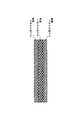
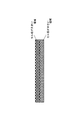
- an aluminum porous body is used as a base material for an electrode of a nonaqueous electrolyte battery (such as a lithium battery), a capacitor using a nonaqueous electrolyte, or a lithium ion capacitor, an active material and a skeleton are formed in a portion having a small cell diameter in the porous body. And the distance will be closer. For this reason, when the three-dimensional reticulated aluminum porous body of the above aspect [1] as shown in FIG. 2 is used as the base material of the electrode, the current collecting property and the active material utilization rate at the central portion in the thickness direction are improved, and the output An electrode having excellent characteristics can be provided.
- a nonaqueous electrolyte battery such as a lithium battery
- a capacitor using a nonaqueous electrolyte, or a lithium ion capacitor an active material and a skeleton are formed in a portion having a small cell diameter in the porous body. And the distance will be closer. For this reason, when the three-dimensional
- the average ratio of the cell diameters of the region 1 and the region 3 to the cell diameter of the region 2 is preferably 1.1 or more. More preferably.
- the ratio of the cell diameter in the region 2 to the average cell diameter in the regions 1 and 3 is less than 1.1, as described above, the current collection at the central portion in the thickness direction is improved and the utilization factor of the active material is improved. It is difficult to obtain the effect.
- the ratio of the cell diameters is calculated from the ratio of these numerical values by measuring the number of skeletons from the micrographs of the respective regions, obtaining the reciprocal number thereof. That is, the average of the reciprocal value of the number of skeletons in region 1 (hereinafter also simply referred to as the reciprocal value) and the reciprocal value of region 3 may be calculated and divided by the reciprocal value of region 2.
- an aluminum porous body in which the ratio of the cell diameter of the regions 1 and 3 to the cell diameter of the region 2 is 1.1 or more in the aluminum porous body manufacturing process described later, It can produce by using such a polyurethane foam. That is, in the polyurethane foaming process, when the foaming material is continuously foamed in a sheet-like mold, the upper and lower surfaces of the mold are warmed to 50 ° C. or more to promote cell growth on the upper and lower surfaces of the sheet. A urethane sheet having a desired cell diameter distribution in the thickness direction is obtained. By plating aluminum on such a urethane sheet and removing the urethane, a porous aluminum body having a ratio of the average cell diameter of the regions 1 and 3 to the cell diameter of the region 2 of 1.1 or more can be obtained.
- the three-dimensional network aluminum porous body of the present invention is a three-dimensional network aluminum porous body in which three aluminum porous bodies A, B, and C are laminated and integrated in this order in the thickness direction.
- the ratio of the average cell diameter of the aluminum porous bodies A and C to the cell diameter of the porous body B is preferably 1.1 or more.
- two types of porous aluminum bodies are prepared: an aluminum porous body having a small cell diameter and an aluminum porous body having a large cell diameter. Then, two aluminum porous bodies A and C having a large cell diameter are laminated so as to sandwich an aluminum porous body B having a small cell diameter, and these are integrated. Thereby, a three-dimensional reticulated aluminum porous body having a large cell diameter in the outer surface layer portion (front surface and back surface) and conversely having a small cell diameter in the inner portion (center layer portion) can be produced. In addition, by stacking and integrating a plurality of aluminum porous bodies, the thickness of the three-dimensional network aluminum porous body can be made thicker than before.
- the aluminum porous bodies A to C are adjusted so that the ratio of the average cell diameter of the cell diameter of the aluminum porous body A and the cell diameter of the aluminum porous body C to the cell diameter of the aluminum porous body B is 1.1 or more.
- the ratio of the cell diameter of the aluminum porous body B and the average cell diameter of the aluminum porous bodies A and C is more preferably 1.5 or more.
- the method for integrating the laminated aluminum porous bodies A to C is not particularly limited. For example, the contact is achieved by raising the temperature to near the melting point of aluminum in a state where pressure is applied to the laminated aluminum porous sheet.
- the skeletons that are connected can be fused and integrated.
- the active material is firmly adhered to the skeleton at the outer surface portion of the aluminum porous body.
- the effect that the retention of the substance is improved is obtained. That is, since the active material is prevented from falling off, the life of the battery is improved and the output characteristics are improved.
- the ratio of the average cell diameter of the cell diameter of the region 1 and the cell diameter of the region 3 to the cell diameter in the region 2 is 0.9 or less. It is preferable that it is 0.7 or less.
- the ratio of the average cell diameter of the regions 1 and 3 to the cell diameter of the region 2 exceeds 0.9, it is difficult to obtain the effect of improving the retention of the active material as described above.
- the ratio of the cell diameters is calculated from the ratio of these numerical values by obtaining the reciprocal of the number of skeletons from the micrograph of each region. That is, the average of the reciprocal value of region 1 and the reciprocal value of region 3 may be calculated and divided by the reciprocal value of region 2.
- an aluminum porous body in which the ratio of the average cell diameter of the cell diameter of the region 1 and the cell diameter of the region 3 to the cell diameter of the region 2 is 0.9 or less It can be produced by using the following polyurethane foam. That is, in the polyurethane foaming process, when the foaming material is continuously foamed in a sheet-like mold, the upper and lower surfaces of the mold are cooled to 5 ° C or less to suppress cell growth on the upper and lower surfaces of the sheet. Thus, a urethane sheet having a desired cell diameter distribution in the thickness direction is obtained.
- the ratio of the average cell diameter of the cell diameter of the region 1 to the cell diameter of the region 3 with respect to the cell diameter of the region 2 is 0.9 or less.
- An aluminum porous body is obtained.
- the three-dimensional network aluminum porous body of the present invention is a three-dimensional network aluminum porous body in which three aluminum porous bodies D, E, and F are laminated and integrated in this order in the thickness direction.
- the ratio of the average cell diameter of the aluminum porous bodies D and F to the cell diameter of the porous body E is preferably 0.9 or less.
- two porous aluminum bodies D and F having a small cell diameter are stacked so as to sandwich an aluminum porous body E having a large cell diameter, and these are integrated.
- a three-dimensional reticulated aluminum porous body having a small cell diameter in the outer surface layer portion (front surface and back surface) and a large cell diameter in the inner portion (center layer portion) can be produced.
- the thickness of the three-dimensional network aluminum porous body can be made thicker than before.
- the aluminum porous bodies D to F are adjusted so that the ratio of the average cell diameter of the cell diameter of the aluminum porous body D and the cell diameter of the aluminum porous body F to the cell diameter of the aluminum porous body E is 0.9 or less.
- the ratio of the cell diameter of the aluminum porous body E to the average cell diameter of the aluminum porous bodies D and F is more preferably 0.7 or less.
- the method for integrating the laminated aluminum porous bodies A to C is not particularly limited. For example, the contact is achieved by raising the temperature to near the melting point of aluminum in a state where pressure is applied to the laminated aluminum porous sheet.
- the skeletons that are connected can be fused and integrated.
- a part of the skeleton located outside the electrode plate is easily cut by bending, and if it is cut, the separator is pierced and causes a short circuit. Therefore, when bending an aluminum porous body in which the cell diameter of the outer portion is large when bent and the cell diameter of the inner portion is adjusted to be small, the skeleton is deformed in the outer portion where the cell diameter is large. Since the amount of displacement until the breakage is large, the skeleton is difficult to cut, and as a result, bending is facilitated and the winding property of the electrode is improved.
- the ratio of the cell diameter of the region 4 to the cell diameter of the region 5 is as follows. It is preferably 1.1 or more, and more preferably 1.5 or more. When the ratio of the cell diameters of the region 5 and the region 4 is less than 1.1, it is difficult to obtain the effect that the winding property is excellent as described above.
- the following polyurethane foam is used in the manufacturing process of the aluminum porous body described later. It can produce by doing. That is, in the polyurethane foaming process, when the foaming material is continuously foamed in a sheet-like mold, the upper surface of the mold is warmed to 50 ° C. or more, or the lower surface is cooled to 5 ° C. or less, thereby The growth of the cells on the upper surface is promoted, the growth of the cells on the lower surface is suppressed, and a urethane sheet having a desired cell diameter distribution in the thickness direction is obtained. By plating aluminum on such a urethane sheet and removing the urethane, a porous aluminum body in which the ratio of the cell diameter of the region 5 to the cell diameter of the region 4 is 1.1 or more is obtained.
- the three-dimensional network aluminum porous body of the present invention is a three-dimensional network aluminum porous body in which two aluminum porous bodies G and H are laminated and integrated in this order in the thickness direction.
- the ratio of the cell diameter of the aluminum porous body G to the cell diameter of H is preferably 1.1 or more.
- a three-dimensional reticulated aluminum porous body in which the cell diameter of the porous aluminum body is not uniform in the thickness direction is produced. be able to.
- the thickness of the three-dimensional network aluminum porous body can be made thicker than before.
- the ratio of the cell diameter of the aluminum porous body G to the cell diameter of the aluminum porous body H is more preferably 1.5 or more.
- the method for integrating the laminated aluminum porous bodies A to C is not particularly limited.
- the contact is achieved by raising the temperature to near the melting point of aluminum in a state where pressure is applied to the laminated aluminum porous sheet.
- the skeletons that are connected can be fused and integrated.
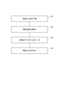
- FIG. 6 is a flowchart showing the manufacturing process of the aluminum structure.
- FIG. 7 schematically shows a state in which an aluminum plating film is formed using a resin molded body as a core material corresponding to the flowchart. The flow of the entire manufacturing process will be described with reference to both drawings.
- preparation 101 of a resin molded body to be a base is performed.
- FIG. 7A is an enlarged schematic view in which the surface of a resin molded body having continuous air holes is enlarged as an example of a resin molded body serving as a base. The pores are formed with the resin molded body 1 as a skeleton.
- the surface 102 of the resin molded body is made conductive. By this step, as shown in FIG.
- a thin conductive layer 2 made of a conductor is formed on the surface of the resin molded body 1.
- aluminum plating 103 in a molten salt is performed to form an aluminum plating layer 3 on the surface of the resin molded body on which the conductive layer is formed (FIG. 7C).
- an aluminum structure in which the aluminum plating layer 3 is formed on the surface using the resin molded body as a base material is obtained.
- removal 104 of the resin molded body is performed for the resin molded body that is the base.
- the aluminum structure (porous body) in which only the metal layer remains can be obtained by dissociating and disappearing the resin molded body 1 (FIG. 7D).
- each step will be described in order.
- a porous resin molded body having a three-dimensional network structure and continuous air holes is prepared.
- Arbitrary resin can be selected as a raw material of a porous resin molding.
- the material include foamed resin moldings such as polyurethane, melamine, polypropylene, and polyethylene.
- foamed resin moldings such as polyurethane, melamine, polypropylene, and polyethylene.
- a resin molded article having an arbitrary shape can be selected as long as it has continuous pores (continuous vent holes). For example, what has a shape like a nonwoven fabric entangled with a fibrous resin can be used instead of the foamed resin molded article.
- the foamed resin molded article preferably has a porosity of 80% to 98% and a pore diameter of 50 ⁇ m to 500 ⁇ m.
- Foamed urethane and foamed melamine can be preferably used as a foamed resin molded article because they have high porosity, have pore connectivity and are excellent in thermal decomposability.
- Urethane foam is preferable in terms of pore uniformity and availability, and urethane foam is preferable in that a material having a small pore diameter can be obtained.
- the porous resin molded body often has residues such as foaming agents and unreacted monomers in the foam production process, and it is preferable to perform a washing treatment for the subsequent steps.
- FIG. 8 shows one obtained by washing urethane foam as a pretreatment.
- the resin molded body forms a three-dimensional network as a skeleton, thereby forming continuous pores as a whole.
- the urethane skeleton has a substantially triangular shape in a cross section perpendicular to the extending direction.
- the porosity is defined by the following equation.
- Porosity (1 ⁇ (weight of porous material [g] / (volume of porous material [cm 3 ] ⁇ material density))) ⁇ 100 [%]
- the surface of the foamed resin is subjected to a conductive treatment in advance.
- a conductive treatment can provide a conductive layer on the surface of the resin molded body, electroless plating of a conductive metal such as nickel, vapor deposition and sputtering of aluminum, or conductive particles such as carbon.
- coating of the conductive paint containing this, can be selected.
- Formation of aluminum layer molten salt plating
- electrolytic plating is performed in a molten salt to form an aluminum plating layer on the surface of the resin molded body.
- a uniformly thick aluminum layer can be formed on the surface of a complicated skeleton structure, particularly a resin molded body having a three-dimensional network structure.
- a direct current is applied in a molten salt using a resin molded body having a conductive surface as a cathode and aluminum having a purity of 99.0% as an anode.
- an organic molten salt that is a eutectic salt of an organic halide and an aluminum halide, or an inorganic molten salt that is a eutectic salt of an alkali metal halide and an aluminum halide can be used.
- Use of an organic molten salt bath that melts at a relatively low temperature is preferable because plating can be performed without decomposing the resin molded body as a base material.
- the organic halide imidazolium salt, pyridinium salt and the like can be used, and specifically, 1-ethyl-3-methylimidazolium chloride (EMIC) and butylpyridinium chloride (BPC) are preferable. Since the molten salt deteriorates when moisture or oxygen is mixed in the molten salt, the plating is preferably performed in an atmosphere of an inert gas such as nitrogen or argon and in a sealed environment.
- an inert gas such as nitrogen or argon
- a molten salt bath containing nitrogen is preferable, and among them, an imidazolium salt bath is preferably used.
- an imidazolium salt bath is preferably used.
- a salt that melts at a high temperature is used as the molten salt, the resin is dissolved or decomposed in the molten salt faster than the growth of the plating layer, and the plating layer cannot be formed on the surface of the resin molded body.
- the imidazolium salt bath can be used without affecting the resin even at a relatively low temperature.
- a salt containing an imidazolium cation having an alkyl group at the 1,3-position is preferably used.
- AlCl 3 + EMIC aluminum chloride + 1-ethyl-3-methylimidazolium chloride
- molten salt is stable. Is most preferably used because it is high and difficult to decompose. Plating onto foamed urethane resin or foamed melamine resin is possible, and the temperature of the molten salt bath is 10 ° C to 65 ° C, preferably 25 ° C to 60 ° C. The lower the temperature, the narrower the current density range that can be plated, and the more difficult it is to plate on the entire porous body surface. At a high temperature exceeding 65 ° C., a problem that the shape of the base resin is impaired tends to occur.
- the smoothness of the plating film is improved, the first feature that the aluminum skeleton forming the porous body is not easily broken, and uniform plating with a small difference in plating thickness between the surface portion and the inside of the porous body is possible.
- the second feature is obtained.
- an organic solvent to the molten salt bath, and 1,10-phenanthroline is particularly preferably used.
- the amount added to the plating bath is preferably 0.2 to 7 g / L. If it is 0.2 g / L or less, it is brittle with plating having poor smoothness, and it is difficult to obtain the effect of reducing the difference in thickness between the surface layer and the inside. On the other hand, if it is 7 g / L or more, the plating efficiency is lowered and it is difficult to obtain a predetermined plating thickness.
- FIG. 9 is a diagram schematically showing a configuration of an apparatus for continuously performing the aluminum plating process on the above-described belt-shaped resin.
- a configuration in which the belt-like resin 22 whose surface is made conductive is sent from the left to the right in the figure.
- the first plating tank 21a includes a cylindrical electrode 24, an anode 25 made of aluminum provided on the inner wall of the container, and a plating bath 23. By passing the strip-shaped resin 22 through the plating bath 23 along the cylindrical electrode 24, a uniform current can easily flow through the entire resin molded body, and uniform plating can be obtained.
- the plating tank 21b is a tank for applying a thick and uniform plating, and is configured to be repeatedly plated in a plurality of tanks.
- Plating is performed by passing the belt-like resin 22 having a conductive surface through a plating bath 28 while sequentially feeding the belt-like resin 22 by an electrode roller 26 that also serves as a feeding roller and an out-of-vessel feeding cathode.
- anodes 27 made of aluminum provided on both surfaces of the resin molded body via a plating bath 28, and uniform plating can be applied to both surfaces of the resin molded body. After sufficiently removing the plating solution from the plated aluminum porous body by nitrogen blowing, the aluminum porous body is obtained by washing with water.
- an inorganic salt bath can be used as the molten salt as long as the resin is not dissolved.
- the inorganic salt bath is typically a binary or multicomponent salt of AlCl 3 —XCl (X: alkali metal).
- Such an inorganic salt bath generally has a higher melting temperature than an organic salt bath such as an imidazolium salt bath, but is less restricted by environmental conditions such as moisture and oxygen, and can be put into practical use at a low cost overall.
- the resin is a foamed melamine resin, it can be used at a higher temperature than the foamed urethane resin, and an inorganic salt bath at 60 ° C. to 150 ° C. is used.
- an aluminum structure having a resin molded body as a skeleton core is obtained.
- the resin and metal composite may be used as they are, but the resin is removed when used as a porous metal body without resin due to restrictions on the use environment.
- the resin is removed by decomposition in a molten salt described below so that oxidation of aluminum does not occur.
- Decomposition in the molten salt is carried out by the following method.
- a resin molded body having an aluminum plating layer formed on the surface is immersed in a molten salt, and the foamed resin molded body is removed by heating while applying a negative potential (potential lower than the standard electrode potential of aluminum) to the aluminum layer.
- a negative potential potential lower than the standard electrode potential of aluminum
- the heating temperature can be appropriately selected according to the type of the foamed resin molded body.
- the temperature of the molten salt bath needs to be 380 ° C. or higher.
- the melting point of the aluminum 660 ° C. or lower is required. It is necessary to process at temperature.
- a preferable temperature range is 500 ° C. or more and 600 ° C. or less.
- the amount of negative potential to be applied is on the minus side of the reduction potential of aluminum and on the plus side of the reduction potential of the cation in the molten salt.
- an alkali metal or alkaline earth metal halide salt in which the electrode potential of aluminum is low can be used.
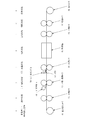
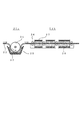
- FIG. 1 is a diagram for explaining an example of a process for continuously producing an electrode from an aluminum porous body.
- the process includes a porous sheet unwinding step A for unwinding the porous sheet from the unwinding roller 41, a thickness adjusting step B using the compression roller 42, and a lead using the compression / welding roller 43 and the lead welding roller 49.
- a winding process H using a winding roller 48.
- the porous aluminum sheet is unwound from the raw roll on which the porous aluminum sheet is wound, and the thickness is adjusted to an optimum thickness by a roller press in the thickness adjusting step, and the surface is flattened.
- the final thickness of the porous aluminum body is appropriately determined depending on the application of the electrode, but this thickness adjusting step is a compression step before the final thickness, and the thickness is easy to process the next step. Compress to a certain extent.
- a flat plate press or a roller press is used as the pressing machine.
- a flat plate press is preferable for suppressing the elongation of the current collector, but is not suitable for mass production, and therefore, it is preferable to use a roller press capable of continuous processing.
- FIG. 10 schematically shows the compression process.
- a rotating roller can be used as the compression jig.
- a predetermined mechanical strength can be obtained by setting the thickness of the compression portion to 0.05 mm or more and 0.2 mm or less (for example, about 0.1 mm).
- the central portion of the aluminum porous body 34 having a width corresponding to two sheets is compressed by the rotating roller 35 as a compression jig to form the compression portion 33.
- the central portion of the compression portion 33 is cut to obtain two electrode current collectors having the compression portion at the end.
- a plurality of band-like compression portions are formed in the central portion of the porous aluminum body using a plurality of rotating rollers, and each of the band-like compression portions is cut along the center line to thereby collect a plurality of collections. An electric body can be obtained.
- a tab lead is joined to the end compression part of the current collector obtained as described above.
- the tab lead it is preferable to use a metal foil to reduce the electric resistance of the electrode and to bond the metal foil to the surface on at least one side of the peripheral edge of the electrode.
- welding it is preferable to use welding as a joining method. If the width of the metal foil to be welded is too large, useless space increases in the battery and the capacity density of the battery decreases, so that it is preferably 10 mm or less. If it is too thin, welding becomes difficult and the current collecting effect is lowered, so 1 mm or more is preferable.
- a welding method a method such as resistance welding or ultrasonic welding can be used, but ultrasonic welding is preferable because the bonding area is wide.
- metal foil As a material of the metal foil, aluminum is preferable in consideration of electric resistance and resistance to an electrolytic solution. In addition, since impurities are eluted and reacted in the battery, capacitor, and lithium ion capacitor, it is preferable to use an aluminum foil having a purity of 99.99% or more. Moreover, it is preferable that the thickness of a welding part is thinner than the thickness of electrode itself. The thickness of the aluminum foil is preferably 20 to 500 ⁇ m.
- the metal foil may be welded either before or after the current collector is filled with the active material, but the active material can be prevented from falling off before being filled. In particular, in the case of ultrasonic welding, it is preferable to perform welding before filling. Moreover, although activated carbon paste may be attached to the welded portion, it may be peeled off during the process, so it is preferable to mask it so that it cannot be filled.
- the compression process of the end portion and the tab lead bonding process are described as separate processes, but the compression process and the bonding process may be performed simultaneously.
- the compression roller a roller part that can be resistance-welded with the roller part that contacts the tab lead joining end of the aluminum porous sheet is used, and the aluminum porous sheet and the metal foil are simultaneously supplied to this roller. The compression and the welding of the metal foil to the compressed portion can be performed simultaneously.
- An electrode is obtained by filling the current collector obtained as described above with an active material.
- the active material is appropriately selected according to the purpose for which the electrode is used.
- a known method such as a dip filling method or a coating method can be used for filling the active material.
- Coating methods include, for example, roll coating method, applicator coating method, electrostatic coating method, powder coating method, spray coating method, spray coater coating method, bar coater coating method, roll coater coating method, dip coater coating method, doctor blade Examples thereof include a coating method, a wire bar coating method, a knife coater coating method, a blade coating method, and a screen printing method.
- FIG. 12 shows a method of filling a porous material with slurry by a roll coating method. As shown in the figure, slurry is supplied onto the porous sheet, and this is passed through a pair of rotating rolls facing each other with a predetermined gap. The slurry is pressed and filled into the porous body when passing through the rotating roll.
- the porous material filled with the active material is carried into a dryer, and the organic solvent is evaporated and removed by heating to obtain an electrode material in which the active material is fixed in the pores of the porous material.
- compression process The electrode material after drying is compressed to a final thickness in a compression process.
- a flat plate press or a roller press is used as the pressing machine.
- a flat plate press is preferable for suppressing the elongation of the current collector, but is not suitable for mass production, and therefore, it is preferable to use a roller press capable of continuous processing.
- the compression process F of FIG. 1 the case where it compresses with a roller press was shown.
- the width of the porous aluminum sheet is set to the width of a plurality of final products, and this is cut by a plurality of blades along the sheet traveling direction. It is preferable to use a long sheet-like electrode material.
- This cutting step is a step of dividing the long electrode material into a plurality of long electrode materials.
- This step is a step of winding a plurality of long sheet-like electrode materials obtained in the cutting step onto a take-up roller.
- Electrodes for non-aqueous electrolyte batteries such as lithium batteries and molten salt batteries
- capacitor electrodes using non-aqueous electrolytes capacitor electrodes using non-aqueous electrolytes
- non-aqueous electrolytes There are electrodes for lithium ion capacitors. Below, these uses are described.
- Lithium battery Next, a battery electrode material and a battery using an aluminum porous body will be described.
- a positive electrode of a lithium battery including a lithium ion secondary battery
- an active material lithium cobaltate (LiCoO 2 ), lithium manganate (LiMn 2 O 4 ), lithium nickelate (LiNiO 2 ) Etc.
- the active material is used in combination with a conductive additive and a binder.
- a conventional positive electrode material for a lithium battery an electrode in which an active material is applied to the surface of an aluminum foil is used.
- Lithium batteries have a higher capacity than nickel metal hydride batteries and capacitors, but there is a need for higher capacities in applications such as automobiles.
- the active material coating thickness must be increased.
- the aluminum foil as the current collector and the active material are in electrical contact with each other. It is used.
- the porous aluminum body of the present invention has a high porosity and a large surface area per unit area. Therefore, since the contact area between the current collector and the active material is increased, the active material can be used effectively, the capacity of the battery can be improved, and the mixing amount of the conductive additive can be reduced.
- the positive electrode material described above is used as a positive electrode, and a copper or nickel foil, a punching metal, a porous body, or the like is used as a current collector for the negative electrode.
- Graphite, lithium titanate (Li 4 Ti 5 O 12 ), Sn An alloy system such as Si or Si, or a negative electrode active material such as lithium metal is used.
- a negative electrode active material is also used in combination with a conductive additive and a binder. Since such a lithium battery can improve capacity even with a small electrode area, the energy density of the battery can be made higher than that of a lithium battery using a conventional aluminum foil.
- the effect on the secondary battery has been mainly described above. However, the effect of increasing the contact area when the porous aluminum body is filled with the active material is the same as that of the secondary battery in the primary battery. Can be improved.
- the electrolyte used for the lithium battery includes a non-aqueous electrolyte and a solid electrolyte.
- FIG. 13 is a longitudinal sectional view of an all-solid lithium battery using a solid electrolyte.
- the all solid lithium battery 60 includes a positive electrode 61, a negative electrode 62, and a solid electrolyte layer (SE layer) 63 disposed between both electrodes.
- the positive electrode 61 includes a positive electrode layer (positive electrode body) 64 and a positive electrode current collector 65
- the negative electrode 62 includes a negative electrode layer 66 and a negative electrode current collector 67.
- a non-aqueous electrolyte described later is used as the electrolyte.
- a separator a porous polymer film, a nonwoven fabric, paper, or the like
- the non-aqueous electrolyte is impregnated in both electrodes and the separator.
- an aluminum porous body When an aluminum porous body is used for a positive electrode of a lithium battery, a material capable of removing and inserting lithium can be used as an active material, and it is suitable for a lithium secondary battery by filling such an aluminum porous body. An electrode can be obtained.
- the material for the positive electrode active material include lithium cobaltate (LiCoO 2 ), lithium nickelate (LiNiO 2 ), lithium nickel cobaltate (LiCo 0.3 Ni 0.7 O 2 ), lithium manganate (LiMn 2 O 4 ), and titanate.
- the active material is used in combination with a conductive additive and a binder.
- transition metal oxides such as olivine compounds which are conventional lithium iron phosphate and its compounds (LiFePO 4 , LiFe 0.5 Mn 0.5 PO 4 ). Further, the transition metal element contained in these materials may be partially substituted with another transition metal element.
- Still other positive electrode active materials include, for example, TiS 2 , V 2 S 3 , FeS, FeS 2 , LiMSx (M is a transition metal element such as Mo, Ti, Cu, Ni, Fe, or Sb, Sn, Pb) ) And the like, and lithium metal having a skeleton of a metal oxide such as TiO 2 , Cr 3 O 8 , V 2 O 5 , and MnO 2 .
- the lithium titanate obtained by the ((Li 4 Ti 5 O 12 ) it is also possible to use as a negative electrode active material.
- Non-aqueous electrolyte a polar aprotic organic solvent is used, and specifically, ethylene carbonate, diethyl carbonate, dimethyl carbonate, propylene carbonate, ⁇ -butyrolactone, sulfolane and the like are used.
- the supporting salt lithium tetrafluoroborate, lithium hexafluorophosphate, and an imide salt are used.
- concentration of the supporting salt serving as an electrolyte is high, a concentration around 1 mol / L is generally used because there is a limit to dissolution.
- Solid electrolyte filled in aluminum porous body In addition to the active material, a solid electrolyte may be added and filled.
- a solid electrolyte By filling an aluminum porous body with an active material and a solid electrolyte, it can be made suitable for an electrode of an all-solid-state lithium battery.
- the proportion of the active material in the material filled in the aluminum porous body is preferably 50% by mass or more, more preferably 70% by mass or more, from the viewpoint of securing the discharge capacity.
- a sulfide-based solid electrolyte having high lithium ion conductivity is preferably used.
- a sulfide-based solid electrolyte having high lithium ion conductivity examples include a sulfide-based solid electrolyte containing lithium, phosphorus, and sulfur. It is done.
- the sulfide solid electrolyte may further contain an element such as O, Al, B, Si, and Ge.
- Such a sulfide-based solid electrolyte can be obtained by a known method.
- lithium sulfide (Li 2 S) and diphosphorus pentasulfide (P 2 S 5 ) are prepared as starting materials, and the ratio of Li 2 S and P 2 S 5 is about 50:50 to 80:20 in molar ratio.
- a method of melting and quenching the mixture melting and quenching method
- a method of mechanically milling the mixture (nocical milling method).
- the sulfide-based solid electrolyte obtained by the above method is amorphous. Although it can be used in this amorphous state, it may be heat-treated to obtain a crystalline sulfide solid electrolyte. Crystallization can be expected to improve lithium ion conductivity.
- the active material for filling the active material (the active material and the solid electrolyte)
- a known method such as an immersion filling method or a coating method
- the coating method include roll coating method, applicator coating method, electrostatic coating method, powder coating method, spray coating method, spray coater coating method, bar coater coating method, roll coater coating method, dip coater coating method, doctor Examples thereof include a blade coating method, a wire bar coating method, a knife coater coating method, a blade coating method, and a screen printing method.
- a conductive additive or binder is added, and an organic solvent or water is mixed therewith to produce a positive electrode mixture slurry.
- This slurry is filled into an aluminum porous body using the above method.
- carbon black such as acetylene black (AB) and ketjen black (KB) and carbon fiber such as carbon nanotube (CNT)
- AB acetylene black
- KB ketjen black
- CNT carbon nanotube
- polyfluoride can be used as the binder, for example.
- Vinylidene (PVDF), polytetrafluoroethylene (PTFE), polyvinyl alcohol (PVA), carboxymethyl cellulose (CMC), xanthan gum and the like can be used.
- the organic solvent used when preparing the positive electrode mixture slurry has an adverse effect on the material (that is, the active material, the conductive additive, the binder, and, if necessary, the solid electrolyte) filled in the aluminum porous body. If not, it can be selected as appropriate.
- organic solvents include n-hexane, cyclohexane, heptane, toluene, xylene, trimethylbenzene, dimethyl carbonate, diethyl carbonate, ethyl methyl carbonate, propylene carbonate, ethylene carbonate, butylene carbonate, vinylene carbonate, vinyl ethylene carbonate.
- the conventional positive electrode material for lithium batteries has apply
- the coating thickness of the active material is increased, and in order to effectively use the active material, the aluminum foil and the active material must be in electrical contact. For this reason, the active material is used in combination with a conductive aid.
- the porous aluminum body of the present invention has a high porosity and a large surface area per unit area. Therefore, since the contact area between the current collector and the active material is increased, the active material can be used effectively, the capacity of the battery can be improved, and the mixing amount of the conductive additive can be reduced.
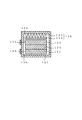
- FIG. 14 is a schematic cross-sectional view showing an example of a capacitor using a capacitor electrode material.
- an electrode material in which an electrode active material is supported on a porous aluminum body is disposed as a polarizable electrode 141.
- the polarizable electrode 141 is connected to the lead wire 144 and is entirely housed in the case 145.
- the aluminum porous body as a current collector, the surface area of the current collector is increased and the contact area with the activated carbon as the active material is increased, so that a capacitor capable of high output and high capacity can be obtained.
- activated carbon is filled as an active material in an aluminum porous body current collector.
- Activated carbon is used in combination with a conductive additive or binder.
- the activated carbon is preferably 90% or more in terms of the composition ratio after drying (after removal of the solvent).
- a conductive auxiliary agent and a binder are necessary, it is a factor of a capacity
- the conductive auxiliary agent is preferably 10% by mass or less, and the binder is preferably 10% by mass or less.
- Activated carbon has a specific surface area of preferably 1000 m 2 / g or more because the capacitor has a larger surface area as the surface area becomes larger.
- Activated carbon can use plant-derived coconut shells, petroleum-based materials, and the like. In order to improve the surface area of the activated carbon, it is preferable to perform activation treatment using water vapor or alkali.
- An activated carbon paste can be obtained by mixing and stirring the electrode material mainly composed of activated carbon.
- the activated carbon paste is filled in the current collector, dried, and compressed by a roller press or the like as necessary, thereby improving the density and obtaining a capacitor electrode.
- the activated carbon can be filled using a known method such as a dip filling method or a coating method.
- a coating method include roll coating method, applicator coating method, electrostatic coating method, powder coating method, spray coating method, spray coater coating method, bar coater coating method, roll coater coating method, dip coater coating method, doctor Examples thereof include a blade coating method, a wire bar coating method, a knife coater coating method, a blade coating method, and a screen printing method.
- a conductive additive or a binder is added as necessary, and an organic solvent or water is mixed therewith to prepare a positive electrode mixture slurry.
- This slurry is filled into an aluminum porous body using the above method.
- carbon black such as acetylene black (AB) and ketjen black (KB) and carbon fiber such as carbon nanotube (CNT)
- AB acetylene black
- KB ketjen black
- CNT carbon nanotube
- polyfluoride can be used as the binder, for example.
- Vinylidene (PVDF), polytetrafluoroethylene (PTFE), polyvinyl alcohol (PVA), carboxymethyl cellulose (CMC), xanthan gum and the like can be used.
- the organic solvent used when preparing the positive electrode mixture slurry has an adverse effect on the material (that is, the active material, the conductive additive, the binder, and, if necessary, the solid electrolyte) filled in the aluminum porous body. If not, it can be selected as appropriate.
- organic solvents include n-hexane, cyclohexane, heptane, toluene, xylene, trimethylbenzene, dimethyl carbonate, diethyl carbonate, ethyl methyl carbonate, propylene carbonate, ethylene carbonate, butylene carbonate, vinylene carbonate, vinyl ethylene carbonate.
- Capacitor production Two of the electrodes obtained as described above are punched out to a suitable size, and are opposed to each other with a separator interposed therebetween.
- the separator it is preferable to use a porous film or non-woven fabric made of cellulose, polyolefin resin, or the like. And it accommodates in a cell case using a required spacer, and impregnates electrolyte solution.
- the electric double layer capacitor can be manufactured by sealing the case with an insulating gasket.
- a non-aqueous material it is preferable to sufficiently dry materials such as electrodes in order to reduce the moisture in the capacitor as much as possible.
- the capacitor may be manufactured in an environment with little moisture, and the sealing may be performed in a reduced pressure environment.
- the capacitor is not particularly limited as long as the current collector and electrode of the present invention are used, and the capacitor may be manufactured by other methods.
- Electrolyte can be used for both aqueous and non-aqueous, but non-aqueous is preferable because the voltage can be set higher.
- potassium hydroxide or the like can be used as an electrolyte.
- non-aqueous systems there are many ionic liquids in combination of cations and anions.
- cation lower aliphatic quaternary ammonium, lower aliphatic quaternary phosphonium, imidazolinium and the like are used, and as the anion, imide compounds such as metal chloride ion, metal fluoride ion, and bis (fluorosulfonyl) imide Etc. are known.
- polar aprotic organic solvents there are polar aprotic organic solvents, and specifically, ethylene carbonate, diethyl carbonate, dimethyl carbonate, propylene carbonate, ⁇ -butyrolactone, sulfolane and the like are used.
- the supporting salt in the non-aqueous electrolyte lithium tetrafluoroborate, lithium hexafluorophosphate, or the like is used.
- FIG. 15 is a schematic cross-sectional view showing an example of a lithium ion capacitor using a lithium ion capacitor electrode material.
- an electrode material having a positive electrode active material supported on an aluminum porous body is disposed as a positive electrode 146
- an electrode material having a negative electrode active material supported on a current collector is disposed as a negative electrode 147.
- the positive electrode 146 and the negative electrode 147 are connected to lead wires 148 and 149, respectively, and are entirely housed in the case 145.
- the aluminum porous body as a current collector, the surface area of the current collector is increased, and a lithium ion capacitor capable of increasing the output and capacity can be obtained even when activated carbon as an active material is thinly applied.
- activated carbon is filled as an active material in an aluminum porous body current collector.
- Activated carbon is used in combination with a conductive additive or binder.
- the activated carbon is preferably 90% or more in terms of the composition ratio after drying (after solvent removal).
- a conductive auxiliary agent and a binder are necessary, it is a factor of a capacity
- the conductive auxiliary agent is preferably 10% by mass or less, and the binder is preferably 10% by mass or less.
- the specific surface area is preferably 1000 m 2 / g or more.
- Activated carbon can use plant-derived coconut shells, petroleum-based materials, and the like. In order to improve the surface area of the activated carbon, it is preferable to perform activation treatment using water vapor or alkali.
- ketjen black, acetylene black, carbon fiber, or a composite material thereof can be used as the conductive auxiliary.
- the binder polyvinylidene fluoride, polytetrafluoroethylene, polyvinyl alcohol, carboxymethyl cellulose, xanthan gum, or the like can be used.
- water or an organic solvent may be appropriately selected depending on the kind of the binder.
- organic solvents N-methyl-2-pyrrolidone is often used.
- surfactant when using water for a solvent, you may use surfactant in order to improve a filling property.
- An activated carbon paste can be obtained by mixing and stirring the electrode material mainly composed of activated carbon.
- the activated carbon paste is filled in the current collector, dried, and compressed by a roller press or the like as necessary, thereby improving the density and obtaining an electrode for a lithium ion capacitor.
- the activated carbon can be filled using a known method such as a dip filling method or a coating method.
- a coating method include roll coating method, applicator coating method, electrostatic coating method, powder coating method, spray coating method, spray coater coating method, bar coater coating method, roll coater coating method, dip coater coating method, doctor Examples thereof include a blade coating method, a wire bar coating method, a knife coater coating method, a blade coating method, and a screen printing method.
- a conductive additive or a binder is added as necessary, and an organic solvent or water is mixed therewith to prepare a positive electrode mixture slurry.
- This slurry is filled into an aluminum porous body using the above method.
- carbon black such as acetylene black (AB) and ketjen black (KB) and carbon fiber such as carbon nanotube (CNT)
- AB acetylene black
- KB ketjen black
- CNT carbon nanotube
- polyfluoride can be used as the binder, for example.
- Vinylidene (PVDF), polytetrafluoroethylene (PTFE), polyvinyl alcohol (PVA), carboxymethyl cellulose (CMC), xanthan gum and the like can be used.
- the organic solvent used when preparing the positive electrode mixture slurry has an adverse effect on the material (that is, the active material, the conductive additive, the binder, and, if necessary, the solid electrolyte) filled in the aluminum porous body. If not, it can be selected as appropriate.
- organic solvents include n-hexane, cyclohexane, heptane, toluene, xylene, trimethylbenzene, dimethyl carbonate, diethyl carbonate, ethyl methyl carbonate, propylene carbonate, ethylene carbonate, butylene carbonate, vinylene carbonate, vinyl ethylene carbonate.
- the negative electrode is not particularly limited, and a conventional negative electrode for a lithium battery can be used.
- the conventional electrode using a copper foil as a current collector has a small capacity, it is made of copper or nickel such as the aforementioned foamed nickel.
- An electrode in which a porous material is filled with an active material is preferable.
- the negative electrode is doped with lithium ions in advance. A known method can be used as the doping method.
- the remaining capacity of the negative electrode is smaller than the positive electrode capacity, the capacity of the lithium ion capacitor is reduced, so the positive electrode capacity is not doped. It is preferable to leave it in
- Electrolytic solution used for lithium ion capacitors The same electrolyte as the nonaqueous electrolyte used for the lithium battery is used.
- a polar aprotic organic solvent is used, and specifically, ethylene carbonate, diethyl carbonate, dimethyl carbonate, propylene carbonate, ⁇ -butyrolactone, sulfolane and the like are used.
- the supporting salt lithium tetrafluoroborate, lithium hexafluorophosphate, and an imide salt are used.
- the electrode obtained as described above is punched out to an appropriate size, and is opposed to the negative electrode with a separator interposed therebetween.
- the negative electrode may be doped with lithium ions by the above-described method, and when a method of doping after assembling the cell is taken, an electrode connected with lithium metal may be arranged in the cell.
- the separator it is preferable to use a porous film or non-woven fabric made of cellulose, polyolefin resin, or the like. And it accommodates in a cell case using a required spacer, and impregnates electrolyte solution. Finally, the case is covered and sealed with an insulating gasket, so that a lithium ion capacitor can be produced.
- the material such as the electrode is sufficiently dried.
- the lithium ion capacitor may be manufactured in an environment with little moisture, and the sealing may be performed in a reduced pressure environment. Note that the lithium ion capacitor is not particularly limited as long as the current collector and the electrode of the present invention are used, and may be manufactured by a method other than this.
- the aluminum porous body can also be used as an electrode material for a molten salt battery.
- a metal compound capable of intercalating cations of molten salt as an electrolyte such as sodium chromite (NaCrO 2 ) and titanium disulfide (TiS 2 ) as an active material Is used.
- the active material is used in combination with a conductive additive and a binder.
- a conductive assistant acetylene black or the like can be used.
- PTFE polytetrafluoroethylene
- PTFE polytetrafluoroethylene
- the aluminum porous body can also be used as a negative electrode material for a molten salt battery.
- an aluminum porous body is used as a negative electrode material
- sodium alone, an alloy of sodium and another metal, carbon, or the like can be used as an active material.
- the melting point of sodium is about 98 ° C., and the metal softens as the temperature rises. Therefore, it is preferable to alloy sodium with other metals (Si, Sn, In, etc.). Of these, an alloy of sodium and Sn is particularly preferable because it is easy to handle.
- Sodium or a sodium alloy can be supported on the surface of the porous aluminum body by a method such as electrolytic plating or hot dipping.
- a metal (such as Si) that is alloyed with sodium is attached to the aluminum porous body by a method such as plating, a sodium alloy can be obtained by charging in a molten salt battery.
- FIG. 16 is a schematic cross-sectional view showing an example of a molten salt battery using the above-described battery electrode material.
- the molten salt battery includes a positive electrode 121 carrying a positive electrode active material on the surface of an aluminum skeleton part of an aluminum porous body, a negative electrode 122 carrying a negative electrode active material on the surface of the aluminum skeleton part of an aluminum porous body, and an electrolyte.
- a separator 123 impregnated with molten salt is housed in a case 127. Between the upper surface of the case 127 and the negative electrode, a pressing member 126 including a pressing plate 124 and a spring 125 that presses the pressing plate is disposed.
- the current collector (aluminum porous body) of the positive electrode 121 and the current collector (aluminum porous body) of the negative electrode 122 are connected to the positive electrode terminal 128 and the negative electrode terminal 129 by lead wires 130, respectively.
- molten salt As the electrolyte, various inorganic salts or organic salts that melt at the operating temperature can be used.
- alkali metals such as lithium (Li), sodium (Na), potassium (K), rubidium (Rb) and cesium (Cs), beryllium (Be), magnesium (Mg), calcium (Ca)
- strontium (Sr) and barium (Ba) can be used.
- the operating temperature can be 90 ° C. or lower.
- a separator is for preventing a positive electrode and a negative electrode from contacting, and a glass nonwoven fabric, a porous resin molding, etc. can be used.
- the above positive electrode, negative electrode, and separator impregnated with molten salt are stacked and housed in a case to be used as a battery.
- Example 1 (Formation of conductive layer)
- a urethane resin molded body a urethane foam having a porosity of 95%, the number of pores per one inch (number of cells), a pore diameter of about 550 ⁇ m, and a thickness of 1 mm was prepared and cut into a 100 mm ⁇ 30 mm square.
- An aluminum film having a basis weight of 10 g / m 2 was formed on the surface of the polyurethane foam by a sputtering method and subjected to a conductive treatment.
- the urethane resin molded body one produced by heating the upper and lower surfaces of the mold to 60 ° C. when continuously foaming the foaming raw material in a sheet-shaped mold in the polyurethane foaming step was used.
- a urethane foam with a conductive layer formed on the surface is set as a work piece in a jig with a power supply function, and then placed in a glove box with an argon atmosphere and low moisture (dew point -30 ° C or less), and melted at a temperature of 40 ° C. It was immersed in a salt aluminum plating bath (33 mol% EMIC-67 mol% AlCl 3 ). The jig on which the workpiece was set was connected to the cathode side of the rectifier, and a counter electrode aluminum plate (purity 99.99%) was connected to the anode side.
- An aluminum structure in which an aluminum plating layer having a weight of 150 g / m 2 was formed on the surface of the urethane foam was obtained by plating by applying a direct current of a current density of 3.6 A / dm 2 for 90 minutes. Stirring was performed with a stirrer using a Teflon (registered trademark) rotor.
- the current density is a value calculated by the apparent area of the urethane foam.
- the aluminum structure was immersed in a LiCl—KCl eutectic molten salt at a temperature of 500 ° C., and a negative potential of ⁇ 1 V was applied for 30 minutes. Bubbles were generated in the molten salt due to the decomposition reaction of the polyurethane. Then, after cooling to room temperature in the atmosphere, the molten salt was removed by washing with water to obtain a porous aluminum body 1 from which the resin was removed. The obtained aluminum porous body had continuous air holes, and the porosity was as high as the urethane foam used as the core material.
- the obtained aluminum porous body was adjusted to a thickness of 0.96 mm by a roller press and cut into 5 cm square.
- a SUS block bar
- a width of 5 mm as a jig for compression and a hammer
- a compressed portion having a thickness of 100 ⁇ m was formed by compression.
- the tab lead was welded by spot welding under the following conditions.
- Example 2 In the polyurethane foaming process, when the foaming material is continuously foamed in a sheet-like mold, the top and bottom surfaces of the mold are cooled to 5 ° C., and the thickness is 1.0 mm, the number of cells is 50, A porous aluminum body 2 was produced in the same manner as in Example 1 except that a urethane resin having a cell diameter of 550 ⁇ m was used. In the same manner as in Example 1, the cross section of the obtained aluminum porous body 2 was observed. The results are as shown in Table 1. The ratio of the reciprocal value of region 1 to the reciprocal value of the number of aluminum skeletons in region 2 was 0.84. Similarly, the ratio of the reciprocal value of region 3 to the reciprocal value of the number of aluminum skeletons in region 2 was 0.84.
- Example 3 In the polyurethane foaming process, when the foaming material is continuously foamed in a sheet-like mold, the upper surface of the mold is heated to 60 ° C. and the lower surface is cooled to 5 ° C.
- a porous aluminum body 3 was produced in the same manner as in Example 1 except that a urethane resin having 0 mm, 50 cells, and a cell diameter of 550 ⁇ m was used.
- the cross section of the obtained aluminum porous body 3 was observed.
- the photomicrograph was divided into two in the thickness direction of the porous body, and one was defined as region 4 and the other as region 5.
- the reciprocal value of the number of aluminum skeletons in the regions 4 and 5 was measured. The results are shown in Table 1.
- the ratio of the reciprocal value of the number of aluminum skeletons in region 4 to the reciprocal value of the number of aluminum skeletons in region 5 was 1.28.
- Example 4 In the polyurethane foaming process, when the foaming material is continuously foamed in a sheet-like mold, the upper and lower surfaces of the mold are made at 25 ° C., the thickness is 0.33 mm, the number of cells is 35, the cell diameter Porous aluminum bodies A and C were obtained in the same manner as in Example 1 except that a urethane resin having a thickness of 790 ⁇ m was used.
- a porous aluminum body B was obtained in the same manner as in Example 1 except that a urethane resin having a cell diameter of 500 ⁇ m was used.
- the obtained aluminum porous bodies A to C are laminated so that the aluminum porous body B is sandwiched between the aluminum porous bodies A and C, and are heated and integrated while applying pressure, whereby the aluminum porous body 4 is obtained. It was. In the same manner as in Example 1, the cross section of the obtained aluminum porous body 4 was observed.
- Example 5 In the polyurethane foaming process, when the foaming material is continuously foamed in a sheet-like mold, the upper and lower surfaces of the mold are made at 25 ° C., the thickness is 0.33 mm, the number of cells is 55, the cell diameter Except for using a urethane resin having a thickness of 500 ⁇ m, porous aluminum bodies D and F were obtained in the same manner as in Example 1.
- a porous aluminum body E was obtained in the same manner as in Example 1 except that a urethane resin having a cell diameter of 790 ⁇ m was used.
- the obtained aluminum porous bodies D to F are laminated so that the aluminum porous bodies D and F sandwich the aluminum porous body E, and are heated and integrated while applying pressure, whereby the aluminum porous body 5 is obtained. It was. In the same manner as in Example 1, the cross section of the obtained aluminum porous body 5 was observed.
- Example 6 In the polyurethane foaming process, when the foaming material is continuously foamed in a sheet-like mold, the upper and lower surfaces of the mold are made at 25 ° C., the thickness is 0.33 mm, the number of cells is 35, the cell diameter An aluminum porous body G was obtained in the same manner as in Example 1 except that a urethane resin having a thickness of 790 ⁇ m was used.
- lithium cobaltate powder positive electrode binder
- the lithium cobaltate powder, acetylene black (conductive aid), and PVDF (binder) are 90% by mass.
- N-methyl-2-pyrrolidone organic solvent
- this positive electrode mixture slurry was filled into the aluminum porous body samples 1 to 7 prepared in Examples 1 to 6 and Comparative Example 1 so that the positive electrode mixture was in the same amount, and then at 100 ° C. for 40 minutes.
- the organic solvent was removed by drying, and further compressed with a roller press (roll gap 0.2 mm) to obtain positive electrode samples 1 to 7.
- Each positive electrode had a thickness of 500 ⁇ m and a capacity per area of 10 mAh / cm 2 .
- an electrolyte type lithium secondary battery was produced as follows.
- samples 1 to 7 punched out to 14 mm ⁇ were used.
- Lithium metal foil (diameter: 15 mm, thickness: 500 ⁇ m) was used for the negative electrode, and was laminated so that a polypropylene separator was interposed between the positive electrode (positive electrode sample) and the negative electrode. This was accommodated in a coin-type battery case having a stainless steel positive electrode can and negative electrode can, and then an organic electrolyte was poured into the battery case.
- organic electrolyte a solution in which 1 mol% of LiClO 4 was dissolved in a mixed organic solvent (volume ratio 1: 1) of propylene carbonate and 1,2-dimethoxyethane was used. After injecting the organic electrolytic solution, a resin gasket was sandwiched between the positive electrode can and the negative electrode can, and the positive electrode can and the negative electrode can were caulked and sealed to produce a coin-type electrolytic lithium secondary battery.
- the electrolyte type lithium secondary battery using the positive electrode samples 1 to 7 was evaluated as follows.
- Example 1 or 4 has better rate characteristics (current collection performance) than Comparative Example 1.
- Example 2 or 5 is more advantageous in cycle characteristics because the active material is held firmly.
- the negative electrode sample was prepared in the same manner as the positive electrode sample, except that the porous aluminum samples 3, 6 and 7 obtained in Examples 3 and 6 and Comparative Example 1 were used, and lithium titanate having an average particle size of 5 ⁇ m was used as the active material.
- the positive electrode samples 3, 6 and 7 were cut into a width of 45 mm and a length of 230 mm, respectively, and aluminum lead wires were welded.
- negative electrode samples 3, 6 and 7 were cut into a width of 45 mm and a length of 280 mm.
- the separator was cut into a width of 50 mm and a length of 500 mm and folded in half, and the positive electrode 3 was sandwiched between the separator 3 and the negative electrode 3 so that the negative electrode was exposed to the outside.
- the electrode group wound using the pair of the positive electrode 6 and the negative electrode 6 and the pair of the positive electrode 7 and the negative electrode 7 was obtained.
- Example 3 or Example 6 it wound so that the one with a larger cell diameter might become an outer side.
- This electrode group was inserted into a negative battery case for a 18650 cylindrical battery, and a positive lead wire and a positive electrode lid with a resin gasket were welded.
- the three-dimensional network aluminum porous body of the present invention as a base material for an electrode, it is possible to improve the current collecting property at the central portion in the thickness direction of the electrode and further improve the internal utilization factor of the active material. In addition, the retention of the active material can be improved. Moreover, winding performance can be improved. For this reason, for example, it can utilize suitably as a base material at the time of manufacturing industrially the electrodes for nonaqueous electrolyte batteries (lithium battery etc.), a nonaqueous electrolyte capacitor, a lithium ion capacitor, etc.
Landscapes
- Engineering & Computer Science (AREA)
- Chemical & Material Sciences (AREA)
- Power Engineering (AREA)
- Materials Engineering (AREA)
- General Chemical & Material Sciences (AREA)
- Electrochemistry (AREA)
- Chemical Kinetics & Catalysis (AREA)
- Microelectronics & Electronic Packaging (AREA)
- Mechanical Engineering (AREA)
- Metallurgy (AREA)
- Organic Chemistry (AREA)
- Manufacturing & Machinery (AREA)
- Cell Electrode Carriers And Collectors (AREA)
- Electric Double-Layer Capacitors Or The Like (AREA)
Abstract
Priority Applications (5)
| Application Number | Priority Date | Filing Date | Title |
|---|---|---|---|
| JP2012557945A JPWO2012111601A1 (ja) | 2011-02-18 | 2012-02-13 | 三次元網状アルミニウム多孔体、該アルミニウム多孔体を用いた電極、該電極を用いた非水電解質電池、非水電解液を用いたキャパシタ及びリチウムイオンキャパシタ |
| DE112012000869T DE112012000869T5 (de) | 2011-02-18 | 2012-02-13 | Poröser Aluminiumkörper mit dreidimensionalem Netzwerk, Elektrode, die den porösen Aluminiumkörper verwendet, und Batterie mit nicht-wässrigem Elektrolyt, Kondensator und Lithium-Ionen-Kondensator mit nicht-wässriger elektrolytischer Lösung, die jeweils die Elektrode verwenden |
| CN201280007333.6A CN103348518B (zh) | 2011-02-18 | 2012-02-13 | 三维网状铝多孔体、使用了该铝多孔体的电极、以及使用了该电极的非水电解质电池、含有非水电解液的电容器和锂离子电容器 |
| KR1020137011789A KR20130143050A (ko) | 2011-02-18 | 2012-02-13 | 3차원 그물 형상 알루미늄 다공체, 당해 알루미늄 다공체를 이용한 전극, 당해 전극을 이용한 비수 전해질 전지, 비수 전해액을 이용한 커패시터 및 리튬 이온 커패시터 |
| US13/539,583 US20130004844A1 (en) | 2011-02-18 | 2012-07-02 | Three-dimensional network aluminum porous body, electrode using the aluminum porous body, and nonaqueous electrolyte battery, capacitor and lithium-ion capacitor with nonaqueous electrolytic solution, each using the electrode |
Applications Claiming Priority (4)
| Application Number | Priority Date | Filing Date | Title |
|---|---|---|---|
| JP2011032902 | 2011-02-18 | ||
| JP2011-032902 | 2011-02-18 | ||
| JP2011-279435 | 2011-12-21 | ||
| JP2011279435 | 2011-12-21 |
Related Child Applications (1)
| Application Number | Title | Priority Date | Filing Date |
|---|---|---|---|
| US13/539,583 Continuation US20130004844A1 (en) | 2011-02-18 | 2012-07-02 | Three-dimensional network aluminum porous body, electrode using the aluminum porous body, and nonaqueous electrolyte battery, capacitor and lithium-ion capacitor with nonaqueous electrolytic solution, each using the electrode |
Publications (1)
| Publication Number | Publication Date |
|---|---|
| WO2012111601A1 true WO2012111601A1 (fr) | 2012-08-23 |
Family
ID=46672520
Family Applications (1)
| Application Number | Title | Priority Date | Filing Date |
|---|---|---|---|
| PCT/JP2012/053249 Ceased WO2012111601A1 (fr) | 2011-02-18 | 2012-02-13 | Maille poreuse tridimensionnelle en aluminium, électrode utilisant ladite maille, batterie à l'électrolyte non aqueux utilisant ladite électrode et condensateur et condensateur au lithium-ion utilisant l'électrolyte liquide non aqueux |
Country Status (6)
| Country | Link |
|---|---|
| US (1) | US20130004844A1 (fr) |
| JP (1) | JPWO2012111601A1 (fr) |
| KR (1) | KR20130143050A (fr) |
| CN (1) | CN103348518B (fr) |
| DE (1) | DE112012000869T5 (fr) |
| WO (1) | WO2012111601A1 (fr) |
Cited By (4)
| Publication number | Priority date | Publication date | Assignee | Title |
|---|---|---|---|---|
| JP2014089916A (ja) * | 2012-10-31 | 2014-05-15 | Tdk Corp | リチウムイオン二次電池用集電体、およびそれを用いたリチウムイオン二次電池 |
| JP2015191702A (ja) * | 2014-03-27 | 2015-11-02 | プライムアースEvエナジー株式会社 | 電池用正極板、アルカリ蓄電池、及び電池用正極板の製造方法 |
| JP2023096441A (ja) * | 2021-12-27 | 2023-07-07 | プライムアースEvエナジー株式会社 | 電池用正極板、電池、及び電池用正極板の製造方法 |
| WO2023181613A1 (fr) * | 2022-03-24 | 2023-09-28 | 住友電気工業株式会社 | Corps poreux métallique |
Families Citing this family (24)
| Publication number | Priority date | Publication date | Assignee | Title |
|---|---|---|---|---|
| EP2579364A4 (fr) | 2010-05-31 | 2016-03-23 | Sumitomo Electric Industries | Matériau poreux d'aluminium de type filet tridimensionnel, électrode constituée du matériau poreux d'aluminium, accumulateur à électrolyte non aqueux équipé de l'électrode et condensateur à solution électrolytique non aqueuse équipé de l'électrode |
| US20140091748A1 (en) | 2012-09-28 | 2014-04-03 | Quantumscape Corporation | Battery control systems |
| US10211443B2 (en) | 2014-09-10 | 2019-02-19 | Cellink Corporation | Battery interconnects |
| US9147875B1 (en) | 2014-09-10 | 2015-09-29 | Cellink Corporation | Interconnect for battery packs |
| CN107408544B (zh) | 2015-02-03 | 2019-09-13 | 塞林克公司 | 用于组合式热能与电能传递的系统及方法 |
| CN106987740A (zh) * | 2017-02-24 | 2017-07-28 | 玉林博飞商贸有限公司 | 一种多孔铝基复合金属材料及其制作方法 |
| KR102256302B1 (ko) | 2017-03-09 | 2021-05-26 | 삼성에스디아이 주식회사 | 전극 조립체 및 이를 포함하는 리튬 전지 |
| WO2019017994A1 (fr) | 2017-07-21 | 2019-01-24 | Quantumscape Corporation | Gestion de pression de batterie active et passive |
| EP3499615A4 (fr) * | 2017-10-25 | 2020-02-05 | Sumitomo Electric Toyama Co., Ltd. | Pile à combustible et procédé de fabrication de corps poreux en métal |
| US11197964B2 (en) | 2017-12-12 | 2021-12-14 | Bigfoot Biomedical, Inc. | Pen cap for medication injection pen having temperature sensor |
| US11116899B2 (en) | 2017-12-12 | 2021-09-14 | Bigfoot Biomedical, Inc. | User interface for diabetes management systems and devices |
| JP7512203B2 (ja) | 2017-12-12 | 2024-07-08 | ビッグフット バイオメディカル インコーポレイテッド | 治療支援情報及び/又は追跡装置並びに関連する方法及びシステム |
| US11083852B2 (en) | 2017-12-12 | 2021-08-10 | Bigfoot Biomedical, Inc. | Insulin injection assistance systems, methods, and devices |
| US10987464B2 (en) | 2017-12-12 | 2021-04-27 | Bigfoot Biomedical, Inc. | Pen cap for insulin injection pens and associated methods and systems |
| US11077243B2 (en) | 2017-12-12 | 2021-08-03 | Bigfoot Biomedical, Inc. | Devices, systems, and methods for estimating active medication from injections |
| US11464459B2 (en) | 2017-12-12 | 2022-10-11 | Bigfoot Biomedical, Inc. | User interface for diabetes management systems including flash glucose monitor |
| KR102143643B1 (ko) * | 2018-08-24 | 2020-08-11 | 주식회사 엘지화학 | 전고체 전지용 전극 또는 고체 전해질의 제조 장치 |
| US12205699B1 (en) | 2018-10-30 | 2025-01-21 | Bigfoot Biomedical, Inc. | Method of pairing therapy devices using shared secrets, and related systems, methods and devices |
| JP7140789B2 (ja) * | 2020-02-14 | 2022-09-21 | 本田技研工業株式会社 | リチウムイオン二次電池用電極、およびリチウムイオン二次電池 |
| CN112599784B (zh) * | 2020-12-16 | 2022-02-11 | 南京邮电大学 | 多孔铝合金集流体及制法、多孔铝合金复合钠负极及制法 |
| JP7149355B2 (ja) * | 2021-01-29 | 2022-10-06 | 本田技研工業株式会社 | リチウムイオン二次電池用電極、及びリチウムイオン二次電池 |
| KR20230160239A (ko) | 2021-03-24 | 2023-11-23 | 셀링크 코포레이션 | 다층 가요성 배터리 인터커넥트 및 이의 제조 방법 |
| CN115071223B (zh) * | 2022-06-29 | 2024-03-15 | 山东裕航特种合金装备有限公司 | 一种多孔铝合金板的制备方法及其应用 |
| CN119069712B (zh) * | 2023-05-31 | 2026-01-06 | 比亚迪股份有限公司 | 集流体及其制备方法和无负极锂金属电池 |
Citations (7)
| Publication number | Priority date | Publication date | Assignee | Title |
|---|---|---|---|---|
| JPH03130395A (ja) * | 1989-10-16 | 1991-06-04 | Katayama Tokushu Kogyo Kk | 電池電極板用金属多孔体の製造方法および該方法により製造された電池電極板用金属多孔体 |
| JPH05325977A (ja) * | 1992-05-27 | 1993-12-10 | Toshiba Battery Co Ltd | アルカリ二次電池用のペースト式電極 |
| JPH07138609A (ja) * | 1993-09-14 | 1995-05-30 | Katayama Tokushu Kogyo Kk | 金属多孔体および該金属多孔体の製造方法 |
| JP2000208144A (ja) * | 1999-01-19 | 2000-07-28 | Sumitomo Electric Ind Ltd | 電池用電極基板とその製造方法 |
| JP2001155739A (ja) * | 1999-11-24 | 2001-06-08 | Nissha Printing Co Ltd | 二次電池用正極および二次電池 |
| JP2002208405A (ja) * | 2001-01-12 | 2002-07-26 | Mitsubishi Materials Corp | 電極用多孔質基体の製造方法 |
| JP2010037569A (ja) * | 2008-07-31 | 2010-02-18 | Mitsubishi Materials Corp | 金属多孔質電極基材およびその製造方法 |
Family Cites Families (13)
| Publication number | Priority date | Publication date | Assignee | Title |
|---|---|---|---|---|
| USRE28470E (en) * | 1966-04-20 | 1975-07-08 | Porous metal structure | |
| JPS5686459A (en) | 1979-12-14 | 1981-07-14 | Matsushita Electric Ind Co Ltd | Spiral-shaped electrode and manufacture thereof |
| US5087245A (en) | 1989-03-13 | 1992-02-11 | Ivac Corporation | System and method for detecting abnormalities in intravascular infusion |
| DE68925580T2 (de) * | 1989-04-14 | 1996-09-19 | Katayama Tokushu Kogyo Kk | Verfahren zur Herstellung einer porösen metallischen Folie |
| JP3568052B2 (ja) | 1994-12-15 | 2004-09-22 | 住友電気工業株式会社 | 金属多孔体、その製造方法及びそれを用いた電池用極板 |
| US5953204A (en) * | 1994-12-27 | 1999-09-14 | Asahi Glass Company Ltd. | Electric double layer capacitor |
| US5851599A (en) * | 1995-09-28 | 1998-12-22 | Sumitomo Electric Industries Co., Ltd. | Battery electrode substrate and process for producing the same |
| JP4292436B2 (ja) * | 1999-05-26 | 2009-07-08 | 住友電気工業株式会社 | 金属多孔質体とその製造方法およびそれを用いた電池用集電体 |
| JP4914059B2 (ja) * | 2005-01-14 | 2012-04-11 | 住友電気工業株式会社 | 集電体、電池用電極基板及びそれらの製造方法 |
| JP4813152B2 (ja) * | 2005-11-14 | 2011-11-09 | 富士重工業株式会社 | リチウムイオンキャパシタ |
| JP5098954B2 (ja) * | 2008-10-28 | 2012-12-12 | 日本ゼオン株式会社 | 電気化学素子用電極の製造方法および電気化学素子 |
| JP5545439B2 (ja) * | 2010-05-31 | 2014-07-09 | 住友電気工業株式会社 | 非水電解質電池 |
| EP2579364A4 (fr) * | 2010-05-31 | 2016-03-23 | Sumitomo Electric Industries | Matériau poreux d'aluminium de type filet tridimensionnel, électrode constituée du matériau poreux d'aluminium, accumulateur à électrolyte non aqueux équipé de l'électrode et condensateur à solution électrolytique non aqueuse équipé de l'électrode |
-
2012
- 2012-02-13 CN CN201280007333.6A patent/CN103348518B/zh active Active
- 2012-02-13 JP JP2012557945A patent/JPWO2012111601A1/ja active Pending
- 2012-02-13 WO PCT/JP2012/053249 patent/WO2012111601A1/fr not_active Ceased
- 2012-02-13 DE DE112012000869T patent/DE112012000869T5/de not_active Withdrawn
- 2012-02-13 KR KR1020137011789A patent/KR20130143050A/ko not_active Ceased
- 2012-07-02 US US13/539,583 patent/US20130004844A1/en not_active Abandoned
Patent Citations (7)
| Publication number | Priority date | Publication date | Assignee | Title |
|---|---|---|---|---|
| JPH03130395A (ja) * | 1989-10-16 | 1991-06-04 | Katayama Tokushu Kogyo Kk | 電池電極板用金属多孔体の製造方法および該方法により製造された電池電極板用金属多孔体 |
| JPH05325977A (ja) * | 1992-05-27 | 1993-12-10 | Toshiba Battery Co Ltd | アルカリ二次電池用のペースト式電極 |
| JPH07138609A (ja) * | 1993-09-14 | 1995-05-30 | Katayama Tokushu Kogyo Kk | 金属多孔体および該金属多孔体の製造方法 |
| JP2000208144A (ja) * | 1999-01-19 | 2000-07-28 | Sumitomo Electric Ind Ltd | 電池用電極基板とその製造方法 |
| JP2001155739A (ja) * | 1999-11-24 | 2001-06-08 | Nissha Printing Co Ltd | 二次電池用正極および二次電池 |
| JP2002208405A (ja) * | 2001-01-12 | 2002-07-26 | Mitsubishi Materials Corp | 電極用多孔質基体の製造方法 |
| JP2010037569A (ja) * | 2008-07-31 | 2010-02-18 | Mitsubishi Materials Corp | 金属多孔質電極基材およびその製造方法 |
Cited By (6)
| Publication number | Priority date | Publication date | Assignee | Title |
|---|---|---|---|---|
| JP2014089916A (ja) * | 2012-10-31 | 2014-05-15 | Tdk Corp | リチウムイオン二次電池用集電体、およびそれを用いたリチウムイオン二次電池 |
| JP2015191702A (ja) * | 2014-03-27 | 2015-11-02 | プライムアースEvエナジー株式会社 | 電池用正極板、アルカリ蓄電池、及び電池用正極板の製造方法 |
| JP2023096441A (ja) * | 2021-12-27 | 2023-07-07 | プライムアースEvエナジー株式会社 | 電池用正極板、電池、及び電池用正極板の製造方法 |
| JP7761481B2 (ja) | 2021-12-27 | 2025-10-28 | トヨタバッテリー株式会社 | 電池用正極板、電池、及び電池用正極板の製造方法 |
| WO2023181613A1 (fr) * | 2022-03-24 | 2023-09-28 | 住友電気工業株式会社 | Corps poreux métallique |
| US12451478B2 (en) | 2022-03-24 | 2025-10-21 | Sumitomo Electric Industries, Ltd. | Metal porous body |
Also Published As
| Publication number | Publication date |
|---|---|
| JPWO2012111601A1 (ja) | 2014-07-07 |
| DE112012000869T5 (de) | 2013-12-24 |
| CN103348518A (zh) | 2013-10-09 |
| KR20130143050A (ko) | 2013-12-30 |
| CN103348518B (zh) | 2016-08-24 |
| US20130004844A1 (en) | 2013-01-03 |
Similar Documents
| Publication | Publication Date | Title |
|---|---|---|
| CN103348518B (zh) | 三维网状铝多孔体、使用了该铝多孔体的电极、以及使用了该电极的非水电解质电池、含有非水电解液的电容器和锂离子电容器 | |
| JP5976551B2 (ja) | 三次元網状アルミニウム多孔体及び該アルミニウム多孔体を用いた電極並びに該電極を用いた非水電解質電池、非水電解液を用いたキャパシタ及びリチウムイオンキャパシタ | |
| WO2011152280A1 (fr) | Matériau poreux d'aluminium de type filet tridimensionnel, électrode constituée du matériau poreux d'aluminium, accumulateur à électrolyte non aqueux équipé de l'électrode et condensateur à solution électrolytique non aqueuse équipé de l'électrode | |
| JP5961117B2 (ja) | 三次元網状アルミニウム多孔体及び該アルミニウム多孔体を用いた電極並びに該電極を用いた非水電解質電池、非水電解液を用いたキャパシタ及びリチウムイオンキャパシタ | |
| WO2012111605A1 (fr) | Maille poreuse tridimensionnelle en aluminium destinée à être utilisée dans un collecteur, collecteur utilisant ladite maille poreuse en aluminium, électrode utilisant ledit collecteur, batterie à électrode non aqueux, condensateur et condensateur au lithium-ion utilisant ladite électrode | |
| JP5883288B2 (ja) | 集電体用三次元網状アルミニウム多孔体、該アルミニウム多孔体を用いた集電体、電極、非水電解質電池、キャパシタ及びリチウムイオンキャパシタ | |
| WO2012111665A1 (fr) | Treillis tridimensionnel en aluminium poreux destiné à être utilisé dans un collecteur, électrode employant celui-ci, et batterie, condensateur et condensateur au lithium-ion employant ladite électrode | |
| WO2012111608A1 (fr) | Collecteur utilisant une maille tridimensionnelle en aluminium poreux, électrode utilisant ledit collecteur, batterie à électrolyte non aqueux utilisant ladite électrode, condensateur et condensateur au lithium-ion utilisant un électrolyte liquide non aqueux, et procédé de fabrication d'électrodes | |
| JPWO2012111659A1 (ja) | 集電体用三次元網状アルミニウム多孔体、該アルミニウム多孔体を用いた電極、非水電解質電池、キャパシタ及びリチウムイオンキャパシタ | |
| US8541134B2 (en) | Electrode using three-dimensional network aluminum porous body, and nonaqueous electrolyte battery, capacitor and lithium-ion capacitor with nonaqueous electrolytic solution, each using the electrode | |
| WO2012111705A1 (fr) | Maille en aluminium poreux tridimensionnelle destinée à un collecteur, électrode utilisant ladite maille, batterie à électrolyte non aqueux utilisant ladite électrode, et condensateur à électrolyte liquide non aqueux et condensateur au lithium-ion | |
| JP5973921B2 (ja) | 三次元網状アルミニウム多孔体、該アルミニウム多孔体を用いた集電体及び電極並びに該電極を用いた非水電解質電池、非水電解液を用いたキャパシタ及びリチウムイオンキャパシタ | |
| JP5876839B2 (ja) | 集電体用三次元網状アルミニウム多孔体、該アルミニウム多孔体を用いた集電体、電極、非水電解質電池、キャパシタ及びリチウムイオンキャパシタ |
Legal Events
| Date | Code | Title | Description |
|---|---|---|---|
| 121 | Ep: the epo has been informed by wipo that ep was designated in this application |
Ref document number: 12746986 Country of ref document: EP Kind code of ref document: A1 |
|
| ENP | Entry into the national phase |
Ref document number: 2012557945 Country of ref document: JP Kind code of ref document: A |
|
| ENP | Entry into the national phase |
Ref document number: 20137011789 Country of ref document: KR Kind code of ref document: A |
|
| WWE | Wipo information: entry into national phase |
Ref document number: 112012000869 Country of ref document: DE Ref document number: 1120120008693 Country of ref document: DE |
|
| 122 | Ep: pct application non-entry in european phase |
Ref document number: 12746986 Country of ref document: EP Kind code of ref document: A1 |