WO2012111668A1 - Appareil de gestion de la charge - Google Patents
Appareil de gestion de la charge Download PDFInfo
- Publication number
- WO2012111668A1 WO2012111668A1 PCT/JP2012/053400 JP2012053400W WO2012111668A1 WO 2012111668 A1 WO2012111668 A1 WO 2012111668A1 JP 2012053400 W JP2012053400 W JP 2012053400W WO 2012111668 A1 WO2012111668 A1 WO 2012111668A1
- Authority
- WO
- WIPO (PCT)
- Prior art keywords
- power
- meter
- amount
- power meter
- electric
- Prior art date
- Legal status (The legal status is an assumption and is not a legal conclusion. Google has not performed a legal analysis and makes no representation as to the accuracy of the status listed.)
- Ceased
Links
Images



Classifications
-
- G—PHYSICS
- G01—MEASURING; TESTING
- G01D—MEASURING NOT SPECIALLY ADAPTED FOR A SPECIFIC VARIABLE; ARRANGEMENTS FOR MEASURING TWO OR MORE VARIABLES NOT COVERED IN A SINGLE OTHER SUBCLASS; TARIFF METERING APPARATUS; MEASURING OR TESTING NOT OTHERWISE PROVIDED FOR
- G01D4/00—Tariff metering apparatus
- G01D4/002—Remote reading of utility meters
-
- B—PERFORMING OPERATIONS; TRANSPORTING
- B60—VEHICLES IN GENERAL
- B60L—PROPULSION OF ELECTRICALLY-PROPELLED VEHICLES; SUPPLYING ELECTRIC POWER FOR AUXILIARY EQUIPMENT OF ELECTRICALLY-PROPELLED VEHICLES; ELECTRODYNAMIC BRAKE SYSTEMS FOR VEHICLES IN GENERAL; MAGNETIC SUSPENSION OR LEVITATION FOR VEHICLES; MONITORING OPERATING VARIABLES OF ELECTRICALLY-PROPELLED VEHICLES; ELECTRIC SAFETY DEVICES FOR ELECTRICALLY-PROPELLED VEHICLES
- B60L53/00—Methods of charging batteries, specially adapted for electric vehicles; Charging stations or on-board charging equipment therefor; Exchange of energy storage elements in electric vehicles
- B60L53/60—Monitoring or controlling charging stations
- B60L53/66—Data transfer between charging stations and vehicles
- B60L53/665—Methods related to measuring, billing or payment
-
- G—PHYSICS
- G01—MEASURING; TESTING
- G01D—MEASURING NOT SPECIALLY ADAPTED FOR A SPECIFIC VARIABLE; ARRANGEMENTS FOR MEASURING TWO OR MORE VARIABLES NOT COVERED IN A SINGLE OTHER SUBCLASS; TARIFF METERING APPARATUS; MEASURING OR TESTING NOT OTHERWISE PROVIDED FOR
- G01D2204/00—Indexing scheme relating to details of tariff-metering apparatus
- G01D2204/40—Networks; Topology
- G01D2204/45—Utility meters networked together within a single building
-
- Y—GENERAL TAGGING OF NEW TECHNOLOGICAL DEVELOPMENTS; GENERAL TAGGING OF CROSS-SECTIONAL TECHNOLOGIES SPANNING OVER SEVERAL SECTIONS OF THE IPC; TECHNICAL SUBJECTS COVERED BY FORMER USPC CROSS-REFERENCE ART COLLECTIONS [XRACs] AND DIGESTS
- Y02—TECHNOLOGIES OR APPLICATIONS FOR MITIGATION OR ADAPTATION AGAINST CLIMATE CHANGE
- Y02B—CLIMATE CHANGE MITIGATION TECHNOLOGIES RELATED TO BUILDINGS, e.g. HOUSING, HOUSE APPLIANCES OR RELATED END-USER APPLICATIONS
- Y02B90/00—Enabling technologies or technologies with a potential or indirect contribution to GHG emissions mitigation
- Y02B90/20—Smart grids as enabling technology in buildings sector
-
- Y—GENERAL TAGGING OF NEW TECHNOLOGICAL DEVELOPMENTS; GENERAL TAGGING OF CROSS-SECTIONAL TECHNOLOGIES SPANNING OVER SEVERAL SECTIONS OF THE IPC; TECHNICAL SUBJECTS COVERED BY FORMER USPC CROSS-REFERENCE ART COLLECTIONS [XRACs] AND DIGESTS
- Y02—TECHNOLOGIES OR APPLICATIONS FOR MITIGATION OR ADAPTATION AGAINST CLIMATE CHANGE
- Y02T—CLIMATE CHANGE MITIGATION TECHNOLOGIES RELATED TO TRANSPORTATION
- Y02T10/00—Road transport of goods or passengers
- Y02T10/60—Other road transportation technologies with climate change mitigation effect
- Y02T10/70—Energy storage systems for electromobility, e.g. batteries
-
- Y—GENERAL TAGGING OF NEW TECHNOLOGICAL DEVELOPMENTS; GENERAL TAGGING OF CROSS-SECTIONAL TECHNOLOGIES SPANNING OVER SEVERAL SECTIONS OF THE IPC; TECHNICAL SUBJECTS COVERED BY FORMER USPC CROSS-REFERENCE ART COLLECTIONS [XRACs] AND DIGESTS
- Y02—TECHNOLOGIES OR APPLICATIONS FOR MITIGATION OR ADAPTATION AGAINST CLIMATE CHANGE
- Y02T—CLIMATE CHANGE MITIGATION TECHNOLOGIES RELATED TO TRANSPORTATION
- Y02T10/00—Road transport of goods or passengers
- Y02T10/60—Other road transportation technologies with climate change mitigation effect
- Y02T10/7072—Electromobility specific charging systems or methods for batteries, ultracapacitors, supercapacitors or double-layer capacitors
-
- Y—GENERAL TAGGING OF NEW TECHNOLOGICAL DEVELOPMENTS; GENERAL TAGGING OF CROSS-SECTIONAL TECHNOLOGIES SPANNING OVER SEVERAL SECTIONS OF THE IPC; TECHNICAL SUBJECTS COVERED BY FORMER USPC CROSS-REFERENCE ART COLLECTIONS [XRACs] AND DIGESTS
- Y02—TECHNOLOGIES OR APPLICATIONS FOR MITIGATION OR ADAPTATION AGAINST CLIMATE CHANGE
- Y02T—CLIMATE CHANGE MITIGATION TECHNOLOGIES RELATED TO TRANSPORTATION
- Y02T90/00—Enabling technologies or technologies with a potential or indirect contribution to GHG emissions mitigation
- Y02T90/10—Technologies relating to charging of electric vehicles
- Y02T90/12—Electric charging stations
-
- Y—GENERAL TAGGING OF NEW TECHNOLOGICAL DEVELOPMENTS; GENERAL TAGGING OF CROSS-SECTIONAL TECHNOLOGIES SPANNING OVER SEVERAL SECTIONS OF THE IPC; TECHNICAL SUBJECTS COVERED BY FORMER USPC CROSS-REFERENCE ART COLLECTIONS [XRACs] AND DIGESTS
- Y02—TECHNOLOGIES OR APPLICATIONS FOR MITIGATION OR ADAPTATION AGAINST CLIMATE CHANGE
- Y02T—CLIMATE CHANGE MITIGATION TECHNOLOGIES RELATED TO TRANSPORTATION
- Y02T90/00—Enabling technologies or technologies with a potential or indirect contribution to GHG emissions mitigation
- Y02T90/10—Technologies relating to charging of electric vehicles
- Y02T90/16—Information or communication technologies improving the operation of electric vehicles
- Y02T90/167—Systems integrating technologies related to power network operation and communication or information technologies for supporting the interoperability of electric or hybrid vehicles, i.e. smartgrids as interface for battery charging of electric vehicles [EV] or hybrid vehicles [HEV]
-
- Y—GENERAL TAGGING OF NEW TECHNOLOGICAL DEVELOPMENTS; GENERAL TAGGING OF CROSS-SECTIONAL TECHNOLOGIES SPANNING OVER SEVERAL SECTIONS OF THE IPC; TECHNICAL SUBJECTS COVERED BY FORMER USPC CROSS-REFERENCE ART COLLECTIONS [XRACs] AND DIGESTS
- Y04—INFORMATION OR COMMUNICATION TECHNOLOGIES HAVING AN IMPACT ON OTHER TECHNOLOGY AREAS
- Y04S—SYSTEMS INTEGRATING TECHNOLOGIES RELATED TO POWER NETWORK OPERATION, COMMUNICATION OR INFORMATION TECHNOLOGIES FOR IMPROVING THE ELECTRICAL POWER GENERATION, TRANSMISSION, DISTRIBUTION, MANAGEMENT OR USAGE, i.e. SMART GRIDS
- Y04S20/00—Management or operation of end-user stationary applications or the last stages of power distribution; Controlling, monitoring or operating thereof
- Y04S20/30—Smart metering, e.g. specially adapted for remote reading
-
- Y—GENERAL TAGGING OF NEW TECHNOLOGICAL DEVELOPMENTS; GENERAL TAGGING OF CROSS-SECTIONAL TECHNOLOGIES SPANNING OVER SEVERAL SECTIONS OF THE IPC; TECHNICAL SUBJECTS COVERED BY FORMER USPC CROSS-REFERENCE ART COLLECTIONS [XRACs] AND DIGESTS
- Y04—INFORMATION OR COMMUNICATION TECHNOLOGIES HAVING AN IMPACT ON OTHER TECHNOLOGY AREAS
- Y04S—SYSTEMS INTEGRATING TECHNOLOGIES RELATED TO POWER NETWORK OPERATION, COMMUNICATION OR INFORMATION TECHNOLOGIES FOR IMPROVING THE ELECTRICAL POWER GENERATION, TRANSMISSION, DISTRIBUTION, MANAGEMENT OR USAGE, i.e. SMART GRIDS
- Y04S30/00—Systems supporting specific end-user applications in the sector of transportation
- Y04S30/10—Systems supporting the interoperability of electric or hybrid vehicles
- Y04S30/14—Details associated with the interoperability, e.g. vehicle recognition, authentication, identification or billing
Definitions
- the present invention relates to a charge management device that manages the amount of charge power of an electric vehicle, a plug-in hybrid vehicle, or the like.
- Electric vehicles such as electric vehicles and plug-in hybrid vehicles (PHV) such as plug-in hybrid vehicles (hereinafter referred to as “electric vehicles”) are housed.
- EV Electric vehicles
- PSV plug-in hybrid vehicles
- electric vehicles When charging with, it is usually necessary to branch a dedicated line from the indoor distribution board and wire it to a parking lot such as an electric vehicle through a breaker with leakage prevention.
- Patent Document 1 discloses a vehicle charging system for a collective housing for charging a vehicle parked in a parking lot of the collective housing using a common light.
- a charging post is installed at each parking position of a parking lot of an apartment house, and each charging post and a management server are communicably connected via a communication line. Centrally manage how many shared lamps are used for charging.
- Non-Patent Document 1 utilizes a function of a delivery box installed in an apartment house, and installs a charging unit (slave unit) at each parking position of an apartment house parking lot.
- a charging system for an electric vehicle is described in which a usage status is grasped and billed by connecting to a parent machine and connecting to a delivery box via an authentication device.
- Patent Document 1 As described above, when charging using a shared power source of an apartment house, it is necessary to grasp how many shared power sources each resident used for charging, but it is described in Patent Document 1 and Non-Patent Document 1.
- a charging system such as the above is introduced into an existing apartment house, a centralized management server, authentication device, etc. are required, so a large installation cost will be incurred, and who will bear the installation cost Is a problem.
- the consent of all residents is required, and there is a problem of cost sharing for residents who do not use electric vehicles.
- the charge management device of the present invention is provided in the middle of a charging wire wired from a common power source to a charging position, measures the power or amount of power used for charging, and transmits the measured value wirelessly or by wire
- the charge management device of the present invention when an electric vehicle or the like is charged using a common power source, the power or the amount of power used for the charging is measured by the child power meter, and the measured value is used for each door. It is transmitted wirelessly or by wire to a parent power meter that measures the amount of power. Then, when the measured value is received by the parent power meter, it is integrated into the used electric energy for each door, so that the fee can be settled as usual based on the used electric energy for each door measured by this parent electric power meter.
- the parent power meter is formed by an inductive watt hour meter that integrates and displays a power amount with a mechanical counter, and depends on the power amount calculated from the power from the child power meter or the measured value indicating the power amount. And adding means for counting up by rotating the mechanical counter.
- the adding means rotates the mechanical counter and counts according to the amount of power obtained by calculating the measurement value from the child power meter.
- the mechanical counter can integrate and display the amount of power used for charging by the electric vehicle or the like and the amount of power used for each door.
- the adding means detects a detection information indicating a carry given to the first digit gear of the mechanical counter, and detects a carry of the first digit gear of the mechanical counter.
- a pulse generation means for generating a number of pulses corresponding to a measured value from the child power meter, and a second digit number of the mechanical counter based on the pulses from the pulse generation means. It is desirable to provide count-up means for rotating the gear.
- the pulse generating means In the mechanical counter, counting is performed by rotating the first digit gear.
- the second digit gear is driven to rotate by the carry of the first digit gear. Therefore, if the rotation by the count-up means overlaps with the carry of the first digit gear, it cannot be counted up accurately. Therefore, the pulse generating means generates the number of pulses corresponding to the measured value from the child power meter in addition to the carry period of the first digit gear detected by the sensor, thereby generating the first digit carry. Overlap with the second digit count-up can be avoided.
- the parent power meter is formed of an inductive watt hour meter that generates an eddy current corresponding to the electric power to rotate the rotating disk and displays the electric energy in an integrated manner, and a rotation detecting unit that detects the rotation of the rotating disk.
- an electric power calculating means for adding the electric energy calculated from the measured value indicating the electric power or the electric energy from the child electric power meter and the electric energy calculated by counting the rotation detected by the rotation detecting means; It is preferable that a power amount display means formed by an electric digital meter for displaying the power amount added by the power calculation means.
- the power calculation means adds the power amount obtained by calculating the measurement value from the child power meter to the parent power meter and the power amount calculated by counting the rotation detected by the rotation detection means.
- the amount and the amount of power used for each door can be integrated and displayed on the electric digital meter.
- the parent power meter includes a measuring unit that measures a current and a voltage in the distribution line, a power amount obtained by calculating power or a power amount from the current and voltage measured by the measuring unit, and the child Power calculating means for adding up the electric power or the electric energy from the electric power meter and adding the electric energy; and an electric energy display means formed by an electric digital meter for displaying the electric energy added by the electric power calculating means; It is desirable to provide.
- the measuring means measures the current and voltage in the distribution line
- the power calculation means adds the amount of power calculated from the current and voltage in the distribution line, and the amount of power from the child power meter, By displaying on the electric energy display means formed by an electric digital meter, even if the parent electric power meter is electric, the electric energy used for charging by the electric vehicle etc. and the electric energy used for each door Can be accumulated and displayed on an electric digital meter.
- the child power meter is formed by an induction type watt hour meter that generates an eddy current according to electric power to rotate the rotating disk and displays the accumulated electric energy, and a rotation detecting means for detecting the rotation of the rotating disk Power calculating means for calculating the amount of power by counting the rotation detected by the rotation detecting means, and communication means for transmitting the amount of power calculated by the power calculating means to the parent power meter. desirable.
- the power calculating means calculates the amount of power from the number of rotations, and the communication means transmits the amount of power to the parent power meter. Even if the meter is formed of a mechanical inductive watt hour meter, the amount of power used for charging by an electric vehicle or the like can be notified to the parent electric meter.
- the child power meter includes a measuring unit that measures a current and a voltage used for charging with the shared power source, a power calculating unit that calculates power or a power amount from the current and voltage measured by the measuring unit, It is desirable to provide communication means for transmitting the amount of power calculated by the power calculation means to the parent power meter.
- the measuring unit measures the current and voltage at the shared power source
- the power calculating unit calculates the amount of power from the current and voltage at the shared power source
- the communication unit transmits the power amount to the parent power meter.
- the charge when an electric vehicle or the like is charged using a common power source, the charge can be settled as usual based on the amount of power used for each door measured by the parent power meter. Even in a single-family house, it is possible to manage each resident with a simple configuration without centrally managing how many shared power sources each resident uses for charging. In addition, there is no need to wire from the indoor distribution board to the charging position, and there is no hole in the wall or no wall is placed on the outer wall, so that the aesthetic appearance is not impaired and the power loss is reduced.
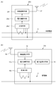
- FIG. 1 It is a schematic block diagram of the charge management apparatus in Embodiment 1 of this invention. It is a schematic block diagram of the charge management apparatus in Embodiment 2 of this invention. It is a schematic block diagram of the parent electric power meter of the charge management apparatus shown in FIG. It is a figure for demonstrating the counter and addition means of the parent power meter shown in FIG. It is a figure for demonstrating the number gear of the counter shown in FIG. 4, a sensor, and identification information. It is a schematic block diagram of the child electric power meter of the charge management apparatus shown in FIG. It is a schematic block diagram of the parent power meter of the charge management apparatus in Embodiment 3 of this invention. It is a figure for demonstrating the charge management apparatus in Embodiment 4 of this invention, (A) is a schematic block diagram of a subpower meter, (B) is a schematic block diagram of a parent power meter.
- FIG. 1 is a schematic configuration diagram of a charge management apparatus according to Embodiment 1 of the present invention.
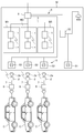
- the charge management device in Embodiment 1 of the present invention is connected between the distribution line 3 and the indoor distribution board 4, and is a parent that measures the power consumption of each house such as a detached house or an apartment house. It includes a power meter 1 and a child power meter 2 provided in the middle of a charging wire 7 wired from a common power source 5 to an outlet 6 of an outdoor parking lot C of an electric vehicle or the like that is a charging position.
- the parent power meter 1 and the child power meter 2 are provided with wireless communication means (not shown) that performs wireless communication with each other by radio waves, light, sound waves, and the like. It transmits to the parent power meter 1 by radio.
- wireless communication means for example, Wi-Fi (registered trademark) standardized by Wi-Fi Alliance, Bluetooth (Bluetooth) specified in IEEE 802.15.1 ) (Registered trademark) or infrared communication can be used. It is also possible to use a mobile communication system such as a third generation mobile communication system (3G).
- the parent electric power meter 1 measures the electric energy used for each door by integrating the electric power used on the indoor distribution board 4 side. The measurement value transmitted by radio from the power meter 2 is received and integrated.
- the child power meter 2 measures the power or the amount of power used for charging the electric vehicle or the like C through the outlet 6, and transmits the measured value to the parent power meter 1 wirelessly.
- the sub power meter 2 measures the amount of power by measuring power or integrating power.
- the child power meter 2 When the child power meter 2 measures power, the child power meter 2 transmits the measured power data to the parent power meter 1 at any time, and integrates this power on the parent power meter 1 side. The amount is added to the power consumption of each door. On the other hand, when the child power meter 2 measures the amount of power, the measured power amount data is transmitted to the parent power meter 1 at a predetermined interval or at a predetermined timing such as after completion of charging. Add this amount of power to the amount of power used by each door.
- the common power source 5 can be a common power source for an apartment house, or a lead-in line from a distribution line such as a distribution line of a utility pole or an underground distribution line. It is of another system. It is desirable to use the common power source 5 as close as possible to the outlet 6 of the outdoor parking lot.
- the electric power or the electric energy used for the charging is measured by the sub power meter 2.
- the measured value is transmitted wirelessly to the parent power meter 1 that measures the amount of power used for each door.
- the parent power meter 1 measures the amount of power used for each door.
- the measured value is received by the parent power meter 1, it is integrated into the used electric energy for each door, so that it is possible to settle the fee as usual based on the used electric energy for each door measured by this parent electric power meter 1. it can.
- this charge management apparatus it is possible to manage each house with a simple configuration without centrally managing how many shared power sources 5 are used by the residents of each house for charging in an apartment house or a detached house. is there.
- no holes are made in the wall, and no external wall is formed, so that the aesthetic appearance is not impaired and the power loss is reduced.
- the parent power meter 1 and the child power meter 2 are configured to include wired communication means (not shown) that perform electrical communication with each other via a communication line such as an electric wire or an optical fiber. It is also possible.
- the wired communication means it is desirable to use, for example, power line communication (PLC; Power Line Communication). In this case, since the parent power meter 1 and the child power meter 2 can perform power line communication using the distribution line 3 and the charging wiring 7, it is not necessary to separately provide a communication line.
- the electric power or the electric energy used for the charging is the child electric power meter 2 as described above.
- the measured value is transmitted by wire to the parent power meter 1 that measures the amount of power used for each door. Then, when the measured value is received by the parent power meter 1, it is integrated into the used electric energy for each door, so that it is possible to settle the fee as usual based on the used electric energy for each door measured by this parent electric power meter 1. it can.
- FIG. 2 is a schematic configuration diagram of the charge management device according to Embodiment 2 of the present invention.
- the same components as those in FIG. 2 are identical components as those in FIG. 2;
- the housing complex M is provided with a power receiving / transforming facility 8 that transforms the power supply from the power company from a high voltage to a low voltage.
- the power receiving / transforming equipment 8 is connected to the parent power meter 1 installed in each of the dwelling units M1 to M3 by the distribution line 3 to each of the dwelling units M1 to M3, and supplies power to each of the dwelling units M1 to M3.
- the power receiving / transforming facility 8 is a shared power source 5 that measures the amount of power of the shared power source 5 to the respective outlets 51 for cleaning the indoor and outdoor lighting and the shared portion of the apartment house M as the shared power source 5. Power is supplied through 52.
- the power receiving / transforming facility 8 supplies power to the outlet 53 connected to a dedicated power line for charging the electric vehicle C or the like as the common power source 5.
- Three child electric power meters 2 are provided so that they can be used in three electric vehicles C owned by the residents of the dwelling units M1 to M3 of the apartment house M.
- the child power meter 2 is connected to a dedicated outlet 53 for charging the common power source 5 by a cable 2a with a plug.
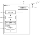
- the parent electric power meter 1 is an induction type watt hour meter that includes a rotating disk 11, a counter driving unit 12, a counter 13, an adding unit 14, and a wireless communication unit 15 for integrating and displaying the electric energy.
- the range of the dotted line surrounding the rotary disk 11, the counter drive means 12, and the counter 13 is the range of the inductive watt hour meter that is generally popular in the home.
- a voltage coil, a current coil, a control magnet, various compensation devices, and the like that rotate the rotating disk 11 are omitted.
- the rotating disk 11 rotates according to the use of electric power.
- the counter driving means 12 forms a screw gear on the rotating shaft of the rotating disk 11, and a helical gear meshes with the screw gear to form a worm gear.
- a gear group for transmitting the rotation is provided.
- the counter 13 is a mechanical counter formed so that the number “0” to “9” is written on the circumferential surface around the rotation axis, and the next digit is carried when the lower digit goes around. is there.
- the adding means 14 calculates the amount of electric power from the measured value notified from the sub power meter 2, and rotates the counter 13 in a state where the used power amount for each door is displayed according to the electric power amount. The amount of power measured by 2 is added.
- the wireless communication means 15 receives the wireless signal from the child power meter 2 via the antenna 16, decodes it, and outputs it to the adding means 14 as a measured value indicating the amount of power.
- the wireless communication unit 15 transmits an answerback indicating that the measurement value has been received to the child power meter 2 or transmits a retransmission request based on a reception error.
- the adding unit 14 includes a pulse generating unit 141, a solenoid 142, and a sensor 143.
- the pulse generating means 141 outputs a number of pulses corresponding to the measured value indicating the amount of power from the child power meter 2 to the solenoid 142 which is a count-up means.
- the solenoid 142 since the solenoid 142 is arranged to count up the second digit gear of the counter 13, one pulse is 1 kWh. Therefore, when the measured value indicating the electric power or the electric energy from the child power meter 2 is an integer value, a pulse is generated based on the value as it is, and when the value includes the decimal part, the decimal part is rounded off.
- a number of pulses based on only the integer value is generated. For example, if there is a notification of the power consumption of 10 kWh as a measurement value from the child power meter 2, the pulse generation means 141 generates 10 pulses. If the position corresponding to the first digit or less of the counter 13 of the measurement value notified from the child power meter 2 (in this case, the value after the decimal point) is added to the measurement value from the next child power meter 2, the fraction The amount of power can be calculated more accurately than processing.
- the solenoid 142 pushes the number gear 131 of the second digit of the counter 13 (1's digit of the electric energy) according to the number of pulses generated by the pulse generating means 141 and protrudes with the movement of the movable iron core (plunger). Is formed by a push-type solenoid that counts up when pressed.
- the sensor 143 notifies the pulse generation unit 141 of the carry of the number gear 132 in the first digit (the first decimal place of the electric energy) of the counter 13.
- a mark (not shown), which is identification information for detecting a carry, is given to the circumferential surface on which the numbers “0” to “9” of the first digit gear 132 of the counter 13 are written. ing. This is because when the counter driving means 12 drives the first digit gear 132 and the number of the first digit gear 132 changes from “9” to “0”, a carry occurs.
- the digit gear 131 is driven by the first digit gear 132 to detect the timing.
- the carry is the number of the first number gear 132. It occurs between “6” (see FIG. 5A) to “8” (see FIG. 5B). Marks that can be detected by the sensor 143 functioning as identification information are assigned to “6” to “8” of the first digit gear 132 of the counter 13.
- the pulse generation means 141 prohibits the output of the drive pulse to the solenoid 142 during the carry period in which the mark is detected. By doing so, it is possible to prevent the carry timing by the first digit gear 132 from overlapping with the addition timing to the second digit gear 131 by the solenoid 142. Therefore, the power amount of the child power meter 2 can be accurately added to the parent power meter 1.
- the carry position is detected by the mark by the sensor 143, but the number may be identified by a paint.
- paint that can be visually recognized and can be detected by the sensor 143 may be applied to “6” to “8” of the first digit gear 132.
- a fluorescent paint can be used as the paint.
- the sensor 143 is arranged right above the counter 13, but can be arranged at any place except the front. For example, when the sensor 143 is disposed on the back surface of the counter 13, the carry identification can be between “4” and ⁇ 6 ”.
- the count-up means includes a gear provided coaxially with the second digit of the counter 13 and the gear is provided with a counter 13 for each pulse. It is also possible to use a stepping motor that rotates one number.
- the parent power meter 1 can reliably add the amount of power notified from the child power meter 2 to the amount of power used for each door.
- the parent electric power meter 1 can be comprised by adding the structure of invention to the existing induction type watt-hour meter.
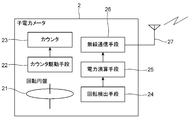
- the child power meter 2 is an inductive watt hour meter including a rotating disk 21, a counter driving unit 22, a counter 23, a rotation detecting unit 24, a power calculating unit 25, and a wireless communication unit 26.
- the rotating disk 21, the counter driving means 22 and the counter 23 can have the same configuration as the rotating disk 11, the counter driving means 12 and the counter 13 of the parent power meter 1.
- the rotation detection means 24 detects the rotation of the rotating disk 21.
- the rotation detecting means 24 receives an LED (Light Emitting Diode) that emits light toward the circumferential surface of the rotating disk 21 and the reflected light from the circumferential surface, and is reduced by a mark applied to the circumferential surface.
- a phototransistor that uses a current signal when light is emitted as a rotation detection signal can be obtained.
- the rotation detecting means 24 can be a rotary encoder that detects a hole provided in the rotating disk 21.
- the power calculation means 25 counts the detection of the rotation of the rotating disk 21 from the rotation detection means 24 and calculates the amount of power.
- the wireless communication unit 26 modulates communication data including a measurement value indicating the amount of power calculated by the power calculation unit 25 and transmits the communication data to the parent power meter 1 through the antenna 27 as a wireless signal. Further, the wireless communication means 26 receives a radio signal from the parent power meter 1 and demodulates it as received data. When the wireless communication means 26 communicates with the wireless communication means 15 of the parent power meter 1, various communication methods can be adopted.
- identification of parent power meter 1 as a communication destination “transmission of a measured value indicating the amount of power”, “reception confirmation of parent power meter 1”, and “confidentiality” are important.
- identification information (ID) for identifying the parent power meter 1 of the dwelling units M1 to M3 is set in advance, so that the transmission destination transmitted by the child power meter 2 can be determined.
- the measurement value is transmitted by being stored in the data portion (data frame) of the packet transmitted by the child power meter 2.
- check data for detecting a communication error on the receiving side is generated and added together with other data.
- the reception confirmation of the parent power meter 1 can be an answerback indicating that the parent power meter 1 has received communication from the child power meter 2.
- the slave power meter 2 assigns a serial number together with the measured value for each communication, and transmits it to the master power meter 1.
- the parent power meter 1 checks whether the serial number is missing, and if the serial number is missing, it can request retransmission by designating the missing serial number. Further, when the slave power meter 2 periodically transmits the measurement value, the transmission time can be used instead of the serial number. If the transmission time interval of the parent power meter 1 is longer than the interval of one time, it can be detected that the transmission of the child power meter 2 is lost. Further, when a communication error is detected in the parent power meter 2, an answer back indicating that a communication error has occurred is returned. In this way, the parent power meter 1 confirms reception, thereby improving communication reliability.
- AES Advanced Encryption Standard
- TKIP Temporal Key Integrity Protocol
- the child power meter 2 notifies the parent power meter 1 of the electric power or the amount of power charged in the electric vehicle C or the like safely and reliably. can do.
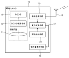
- FIG. 7 is a schematic configuration diagram of a parent power meter of the charge management device according to Embodiment 3 of the present invention.
- the parent power meter 10 shown in FIG. 7 can be used in place of the parent power meter 1 of the charge management apparatus in the second embodiment shown in FIG.
- the parent power meter 10 has the same configuration as the rotating disk 11, counter driving means 12, counter 13, wireless communication means 15, and antenna 16 of the parent power meter 1 shown in FIG. 3, and the child shown in FIG.
- the power meter 2 has the same configuration as the rotation detection means 24 of the power meter 2, a power calculation means 17, and a power amount display means 18.
- the range of the dotted line surrounding the rotating disk 11, the counter driving means 12, and the counter 13 is the range of the inductive watt hour meter that is generally popular in the home.
- the voltage coil and current coil for rotating the rotating disk 11, the control magnet, and various compensation devices are omitted.
- the power calculation means 17 integrates the power amount notified from the child power meter 2 to calculate the power amount used for charging the electric vehicle or the like C, and at the same time the rotation of the rotary disk 21 from the rotation detection means 24. The number of detections is counted, the amount of power used for each door is calculated, these amounts of power are added, and output to the power amount display means 18.
- the power calculation means 17 is preferably stored in a nonvolatile memory so that the added power amount can be maintained even during a power failure.
- the non-volatile memory can be a battery-backed memory or a flash memory.
- the electric energy display means 18 is an electric digital meter such as a liquid crystal panel, an EL (Electro Luminescence) panel, and a 7-segment LED.
- the parent power meter 10 calculates the power amount obtained by calculating the measurement value from the child power meter 2, and the power amount calculated by counting the rotation detected by the rotation detecting means 24, Even if the parent power meter 10 is formed by a mechanical inductive watt hour meter, the power calculation unit 17 adds and displays on the power amount display unit 18 formed by an electric digital meter.
- the electric power used by the electric vehicle or the like C for charging and the electric power used for each door can be integrated and displayed on the electric digital meter.
- the parent electric power meter 10 can be comprised by adding the structure of invention to the existing induction type watt-hour meter.
- FIGS. 8A and 8B are diagrams for explaining the charge management device according to the fourth embodiment of the present invention.
- FIG. 8A is a schematic configuration diagram of a child power meter
- FIG. 8B is a schematic configuration diagram of a parent power meter.
- the same components as those in FIGS. 3, 6, and 7 are given the same reference numerals and description thereof is omitted.
- a child power meter 20x shown in FIG. 8A can be used in place of the child power meter 2 of the charge management device in the third embodiment shown in FIG. 6, and the parent power meter 10x shown in FIG.
- the parent power meter 1 of the charge management apparatus in the second embodiment shown in FIG. 3 and the parent power meter 10 of the charge management apparatus in the third embodiment shown in FIG. 7 can be used.
- the child power meter 20x and the parent power meter 10x according to the fourth embodiment electrically measure power and display it electrically.
- a child power meter 20x shown in FIG. 8A includes a power measuring unit 28x, a power calculating unit 25x, and a wireless communication unit 26.
- the power measuring means 28x measures the current and voltage used for charging the shared power supply and notifies the power calculating means 25x.
- the power calculation means 25x calculates the power or the amount of power from the current and voltage measured by the power measurement means 28x, and transmits it to the parent power meter 10x via the wireless communication means 26.
- a child power meter 20x shown in FIG. 8A includes a measuring unit 28x, a power calculating unit 25x, and a wireless communication unit 26.
- the measuring means 28x measures the current and voltage used for charging the shared power supply 5 and notifies the power calculating means 25x.
- the power calculation means 25x calculates the power or the amount of power from the current and voltage measured by the measurement means 28x, and transmits it to the parent power meter 10x via the wireless communication means 26.
- a parent power meter 10x shown in FIG. 8B includes a measuring unit 19x, a power calculating unit 17x, a wireless communication unit 15, and a power amount display unit 18.
- the measuring unit 19x measures the current and voltage used in each dwelling unit of the distribution line 3 and notifies the power calculating unit 17x of the same as the measuring unit 25x.
- the power calculation unit 17x is configured to calculate the power or the power amount from the current and voltage measured by the measurement unit 28x, and the power from the slave power meter 20x received via the wireless communication unit 15 or The sum of the electric energy is added and displayed by the electric energy display means 18.
- the power calculation means 17x and the power calculation means 25x are preferably stored in a non-volatile memory so that the calculated amount of power can be maintained even during a power failure.
- the non-volatile memory can be a battery-backed memory or a flash memory.
- the measuring unit 28x measures the current and voltage at the shared power source 5
- the power calculating unit 25x calculates the amount of power from the current and voltage at the shared power source
- the wireless communication unit 26 By adopting a configuration in which the amount of electric power is transmitted to the parent electric power meter 10x, even if the child electric power meter 20x is an electric type, the electric amount used for charging by the electric vehicle or the like C can be notified to the parent electric meter 10x. .
- the measuring means 19x measures the current and voltage in the distribution line 3
- the power calculation means 17x calculates the amount of power calculated from the current and voltage in the distribution line 3
- the child power meter 20x By adding the electric energy and displaying the electric energy on the electric energy display means 18 formed by an electric digital meter, even if the parent electric power meter 10x is electric, the electric vehicle or the like C is charged. The amount of power used and the amount of power used for each door can be integrated and displayed on an electric digital meter.
- the charge management device is not limited to the mechanical type such as the inductive watt hour meter and the electronic type of the parent power meter 10x and the child power meter 20x. It is possible to manage each shared power supply 5 with a simple configuration without centralized management.
- the slave power meter wirelessly communicates the measured value to the parent power meter between the slave power meter and the master power meter by wireless communication means.
- wired communication may be performed by wired communication means. If there is a one-to-one wired communication between the child power meter and the parent power meter, there is no need to designate the parent power meter by an address. In this case, the child power meter has a predetermined integrated power. This may be notified by one pulse, and the parent power meter may count the pulse and integrate the amount of power used for charging. By doing so, it is possible to provide a simple interface for wired communication.
- the power meter 20x can be combined with each other by combining communication interfaces.
- the charge management device of the present invention is useful as a device for managing the amount of charge power of an electric vehicle, a plug-in hybrid vehicle, or the like.
Landscapes
- Engineering & Computer Science (AREA)
- Physics & Mathematics (AREA)
- General Physics & Mathematics (AREA)
- Power Engineering (AREA)
- Transportation (AREA)
- Mechanical Engineering (AREA)
- Remote Monitoring And Control Of Power-Distribution Networks (AREA)
- Charge And Discharge Circuits For Batteries Or The Like (AREA)
Abstract
L'invention concerne un appareil de gestion de la charge avec lequel, lorsque la charge d'une automobile électrique ou similaire est réalisée en utilisant une source d'énergie partagée non seulement dans le cas d'une résidence collective, mais également dans le cas d'une résidence individuelle, la gestion du niveau auquel la source d'énergie partagée a été utilisée pour la charge par les occupants de chaque résidence est effectuée pour chaque résidence individuelle au moyen d'une construction simple sans gestion centralisée. Un appareil de gestion de la charge comprend : un appareil de mesure de puissance secondaire (2) qui se trouve à mi-chemin sur un câble de charge (7) posé entre une source d'énergie partagée (5) et l'emplacement de la charge, mesure l'énergie ou la quantité d'énergie utilisée dans la charge et transmet la valeur mesurée sans fil ou au moyen de fils ; et un appareil de mesure de puissance principal (1) qui mesure la quantité d'énergie utilisée par chaque résidence, reçoit la valeur mesurée transmise par l'appareil de mesure de puissance secondaire (2) et intègre celle-ci avec la quantité d'énergie utilisée pour chaque résidence.
Priority Applications (1)
| Application Number | Priority Date | Filing Date | Title |
|---|---|---|---|
| JP2012557975A JP5859465B2 (ja) | 2011-02-18 | 2012-02-14 | 充電管理装置 |
Applications Claiming Priority (2)
| Application Number | Priority Date | Filing Date | Title |
|---|---|---|---|
| JP2011033753 | 2011-02-18 | ||
| JP2011-033753 | 2011-02-18 |
Publications (1)
| Publication Number | Publication Date |
|---|---|
| WO2012111668A1 true WO2012111668A1 (fr) | 2012-08-23 |
Family
ID=46672586
Family Applications (1)
| Application Number | Title | Priority Date | Filing Date |
|---|---|---|---|
| PCT/JP2012/053400 Ceased WO2012111668A1 (fr) | 2011-02-18 | 2012-02-14 | Appareil de gestion de la charge |
Country Status (2)
| Country | Link |
|---|---|
| JP (1) | JP5859465B2 (fr) |
| WO (1) | WO2012111668A1 (fr) |
Families Citing this family (1)
| Publication number | Priority date | Publication date | Assignee | Title |
|---|---|---|---|---|
| US11794603B2 (en) * | 2021-11-15 | 2023-10-24 | Iotecha Corp. | Methods, devices, and systems for submetering of an electric vehicle (EV) charging session |
Citations (2)
| Publication number | Priority date | Publication date | Assignee | Title |
|---|---|---|---|---|
| JPH11144177A (ja) * | 1997-11-06 | 1999-05-28 | Matsushita Electric Ind Co Ltd | 機器別検針システム |
| JP2010200521A (ja) * | 2009-02-26 | 2010-09-09 | Chugoku Electric Power Co Inc:The | 電力使用量加算システム |
Family Cites Families (3)
| Publication number | Priority date | Publication date | Assignee | Title |
|---|---|---|---|---|
| JP2010110044A (ja) * | 2008-10-28 | 2010-05-13 | Shikoku Electric Power Co Inc | 電動車両用充電装置 |
| JP4821833B2 (ja) * | 2008-10-28 | 2011-11-24 | パナソニック電工株式会社 | 充電ケーブルユニット及びそれを用いた充電システム |
| JP2010187451A (ja) * | 2009-02-11 | 2010-08-26 | Chubu Electric Power Co Inc | 集合住宅用の車両充電システム及び充電用端末 |
-
2012
- 2012-02-14 JP JP2012557975A patent/JP5859465B2/ja active Active
- 2012-02-14 WO PCT/JP2012/053400 patent/WO2012111668A1/fr not_active Ceased
Patent Citations (2)
| Publication number | Priority date | Publication date | Assignee | Title |
|---|---|---|---|---|
| JPH11144177A (ja) * | 1997-11-06 | 1999-05-28 | Matsushita Electric Ind Co Ltd | 機器別検針システム |
| JP2010200521A (ja) * | 2009-02-26 | 2010-09-09 | Chugoku Electric Power Co Inc:The | 電力使用量加算システム |
Non-Patent Citations (1)
| Title |
|---|
| "Denryokuryokei", 9 February 2011 (2011-02-09), Retrieved from the Internet <URL:http://ja.wikipedia.org/w/index.php?title=Denryokuryokei&oldid=36270632> [retrieved on 20120511] * |
Also Published As
| Publication number | Publication date |
|---|---|
| JPWO2012111668A1 (ja) | 2014-07-07 |
| JP5859465B2 (ja) | 2016-02-10 |
Similar Documents
| Publication | Publication Date | Title |
|---|---|---|
| JP5026530B2 (ja) | ユーティリティ監視装置、その監視システム及びその監視方法 | |
| KR101448612B1 (ko) | 전기자동차 충전에 따른 과금시스템 | |
| TWI633023B (zh) | 基於位置的電力仲介用模組、電動車及仲介伺服器 | |
| KR101208320B1 (ko) | 공동주택용 전기자동차 충전 시스템 및 이 시스템을 이용한 전기자동차 충전 방법 | |
| CN102387191B (zh) | 电动车辆远程管理系统 | |
| JP5868179B2 (ja) | 電気エネルギーの計測・測定用メータリングポイントシステム及び方法 | |
| KR101261200B1 (ko) | 능동형 원격검침시스템 | |
| JP2011010547A5 (fr) | ||
| JP2010146568A (ja) | 車両用電力計測システム及び方法 | |
| EP2408639A2 (fr) | Procédé, système et appareil permettant de contrôler et de réguler une distribution d'électricité à des véhicules électriques | |
| JP2013003032A (ja) | 水道メータ検知装置 | |
| KR101828593B1 (ko) | 사용자 휴대단말기를 이용한 전기자동차용 모바일충전기의 충전시스템 | |
| KR20160088135A (ko) | 휴대용 단말기를 이용한 검침시스템 및 그 검침방법 | |
| JP5859465B2 (ja) | 充電管理装置 | |
| JP2012243424A (ja) | 電気自動車またはプラグインハイブリッド車用の充電システム | |
| JP6187922B2 (ja) | 充電システム、情報端末 | |
| KR20190021596A (ko) | 지능형 전력계량 인프라와 연계하여 전기차량의 가정용 ac 전원 충전 시 과금 서비스를 제공하는 완속충전 케이블 및 이를 이용한 과금 서비스 제공방법 | |
| JP2011180738A (ja) | 電力計測装置並びに電力計測システム | |
| KR101067299B1 (ko) | 원격계량용 모뎀 | |
| US20130174249A1 (en) | Secure lock function for an endpoint | |
| GB2452072A (en) | Wireless communications enabled metering for Energy Monitoring, Control and home management | |
| KR20200005029A (ko) | 전류 패턴 기반 전력량계 식별방법 | |
| KR20050092617A (ko) | 원격 검침 장치 및 상기 원격 검침 장치를 이용한 원격검침 시스템 | |
| KR100799071B1 (ko) | 오결선 검침 기능을 갖는 원격검침 시스템 | |
| KR20110133729A (ko) | 근거리 무선통신을 이용한 스마트 스위치 방법 및 시스템 |
Legal Events
| Date | Code | Title | Description |
|---|---|---|---|
| 121 | Ep: the epo has been informed by wipo that ep was designated in this application |
Ref document number: 12747747 Country of ref document: EP Kind code of ref document: A1 |
|
| DPE1 | Request for preliminary examination filed after expiration of 19th month from priority date (pct application filed from 20040101) | ||
| ENP | Entry into the national phase |
Ref document number: 2012557975 Country of ref document: JP Kind code of ref document: A |
|
| NENP | Non-entry into the national phase |
Ref country code: DE |
|
| 122 | Ep: pct application non-entry in european phase |
Ref document number: 12747747 Country of ref document: EP Kind code of ref document: A1 |