WO2012114371A1 - Dispositif de transmission de message et procédé de transmission de message - Google Patents
Dispositif de transmission de message et procédé de transmission de message Download PDFInfo
- Publication number
- WO2012114371A1 WO2012114371A1 PCT/JP2011/000998 JP2011000998W WO2012114371A1 WO 2012114371 A1 WO2012114371 A1 WO 2012114371A1 JP 2011000998 W JP2011000998 W JP 2011000998W WO 2012114371 A1 WO2012114371 A1 WO 2012114371A1
- Authority
- WO
- WIPO (PCT)
- Prior art keywords
- message
- protocol
- network
- data
- transmitting
- Prior art date
- Legal status (The legal status is an assumption and is not a legal conclusion. Google has not performed a legal analysis and makes no representation as to the accuracy of the status listed.)
- Ceased
Links
Images


Classifications
-
- H—ELECTRICITY
- H04—ELECTRIC COMMUNICATION TECHNIQUE
- H04L—TRANSMISSION OF DIGITAL INFORMATION, e.g. TELEGRAPHIC COMMUNICATION
- H04L69/00—Network arrangements, protocols or services independent of the application payload and not provided for in the other groups of this subclass
- H04L69/18—Multiprotocol handlers, e.g. single devices capable of handling multiple protocols
Definitions
- the present invention relates to an apparatus and a method for transmitting data to a message receiving apparatus.
- a technology called smart grid which introduces IT technology in the field of power control and promotes efficient use of power, is attracting attention.
- network communication technology is used to transmit and receive information between devices constituting the smart grid.
- the data center device may directly send a command to the device via this network.
- private information such as the amount of power used and the usage time of power equipment may be transmitted and received. For example, if information on the usage time of an air conditioner is leaked in summer, the user's staying time becomes clear, and it can be misused for crimes such as vacant nests. In order to transmit and receive these pieces of information, a stable communication operation is required.
- Patent Document 1 discloses a technique for monitoring a network state between devices and controlling the protocol in the same protocol according to the network state. Specifically, when a link abnormality such as congestion is detected by monitoring the network by SNMP, a network traffic control is performed by transmitting a signal such as congestion control.
- the present invention relates to a message transmission device that transmits data to a message reception device, based on the reception unit that receives data including information about the state of the message reception device with respect to the network, and the received information about the state of the network.
- a determination unit that determines a state of the message reception device with the network, a protocol selection unit that selects a protocol based on the determined network state, and a transmission unit that transmits data to the message reception device using the protocol It is characterized by.
- data can be transmitted between devices even in a situation where communication is unstable.
- FIG. 2 is a diagram illustrating an example of the configuration of a data center apparatus 100.
- FIG. 3 is a diagram illustrating an example of the configuration of a home server 101.
- FIG. 3 is an exemplary diagram of a configuration of a power device 103.
- FIG. 4 is a diagram illustrating an example of the configuration of a display terminal 104.
- FIG. 6 is a diagram showing an example of the configuration of a message transmission policy DB 207.
- FIG. 4 is a diagram illustrating an example of the configuration of a use protocol determination policy DB 208.
- FIG. 4 is a diagram illustrating an example of the configuration of a network status DB 210.
- FIG. 1 The figure of an example of a structure of network status determination DB211.
- FIG. The flowchart which is an example of the flow of a process of the electric energy transmission program 507.
- FIG. 1 is a diagram showing an entire system for carrying out the present invention.
- the data center apparatus 100 is a computer for transmitting / receiving information to / from the home server 101, the adapter 102, the power device 103, the display terminal 104, and the like connected to the data center apparatus 100.
- the data center device 100 is connected to a plurality of houses (house 1000, house 1001) via a network 105.
- the home server 101 is a computer that exists between the data center apparatus 101, the power device 103, and the display apparatus 104 and transmits and receives data.
- the home server 101 is connected to the data center apparatus 100 via the network 105.
- the network 105 is a network that exchanges packets such as TCP and UDP, for example, like the Internet.
- the home server 101 is also connected to the adapter 102 via the network 106.
- the network 106 is a local network in a home, for example, and packets such as TCP and UDP are exchanged in a LAN environment.
- the adapter 102 is a computer that receives data from the power device 103 and the display terminal 104 and transmits data to the data center device 100 via the home server 101.
- the adapter 102 is connected to the power device 103 and the display terminal 104 through the communication path 107.
- the communication path 107 is, for example, an IP network, a PLC (power line communication) network, or a wireless communication network that communicates using TCP, which is a protocol with a high network load, or UDP, which is a protocol with a low network load.
- the IP network is a network that communicates using the Internet protocol
- TCP and UDP are names of protocols that perform communication in an upper layer of the Internet protocol.
- UDP only sends a packet from one device participating in the network to another device, whereas TCP checks the arrival of packets and the order of arrival at the protocol level. . Therefore, when the two protocols are compared, communication with a higher security level is guaranteed with TCP. Also, because TCP has more data than UDP, network congestion is likely to occur.
- the power device 103 is a device that consumes power.
- the power device 103 is a home device such as an air conditioner or a blind, for example. However, it is assumed here that the blind has a power unit that can be opened and closed by an instruction from the outside.
- the display terminal 104 is a terminal for displaying information acquired through the communication path 107.
- the display terminal 104 is a television, for example.
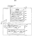
- FIG. 2 is a diagram showing the configuration of the data center apparatus 100.
- the data center apparatus 100 is a computer including a CPU 201, a storage device 202, a memory 203, and an interface 204 (hereinafter, the interface is referred to as IF in the figure) input / output device 205, which are connected via a communication path 206. ing.
- the storage device 202 includes data processed by the CPU 206. It is a storage device such as a hard disk device, and stores the following data processed by the data center device 100.
- DB means database.
- the message transmission policy DB 207 is a database that defines a correspondence between a network state and a message to be transmitted in that state.
- the used protocol determination policy DB 208 is a database that defines which protocol is used depending on the network state.
- the transmission message DB 209 is a database that stores the contents of messages to be transmitted according to the network status.
- the network status DB 210 is a database for storing data such as the network execution transfer rate and the packet loss rate.
- the network status determination DB 211 is a database that defines conditions relating to the network status and the rank of the network status under the conditions.
- the memory 203 is a storage medium that includes a program processed by the CPU 201, and includes the following programs.
- Network property collection program 212 collects information such as packet loss and transfer rate from the network to determine the network status, and the message transmission program 213 selects an appropriate protocol message according to the network status and transmits it. It is a program to do. There may be an implementation in which the program is temporarily recorded in the storage device 202 and read into the memory 203 and executed when the CPU 201 executes the program.
- the network property collection program 212 stores a reception unit 220 and a network determination unit 221.
- the receiving unit 220 acquires data received by the data center device 100.
- the network determination unit 221 determines the status of the network.
- the message transmission program 213 stores a message selection unit 222, a protocol selection unit 223, and a transmission unit 224.
- the message selection unit 222 selects a message transmitted by the data center device 100.
- the protocol selection unit 223 selects a protocol transmitted by the data center device 100.
- the transmission unit 224 transmits the message generated by the data center device 100.
- the interface 204 is a communication interface for performing external communication with the data center apparatus 100.
- the interface 204 is connected to the external network 105.
- the input / output device 205 is a device for inputting / outputting data to / from the data center device 100, and is, for example, a display, a keyboard, or a mouse.
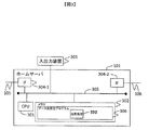
- FIG. 3 is a diagram showing the configuration of the home server 101.
- the home server 101 is a computer including a CPU 301, a memory 302, an input / output device 303, and an interface 304, which are connected via a communication path 305.
- the memory 302 is a storage medium that includes a program processed by the CPU 301, and includes a data transmission / reception program 306.
- the data transmission / reception program 306 stores a transmission / reception unit 320.
- the transmission / reception unit 320 acquires data received by the home server 101 and transmits a message generated by the home server 101.
- the input / output device 303 is a device for inputting / outputting data to / from the home server, such as a display, a keyboard, and a mouse.
- An interface 304 is a communication interface for performing external communication with the data center apparatus 100.
- the interfaces 304-1 and 304-2 are connected to different networks, and connect the two networks.
- the interface 304-1 is connected to the external network 105, and the interface 304-2 is connected to the home network 106.
- FIG. 4 is a diagram illustrating the configuration of the adapter 102.
- An adapter is a device that converts data media.
- the adapter 102 is a computer including a CPU 401, a memory 402, an input / output device 403, and an interface 404, which are connected via a communication path 405.
- the memory 402 is a storage medium that includes a program processed by the CPU 401, and includes a data transmission / reception program 406.
- the data transmission / reception program 406 stores a transmission / reception unit 420.
- the transmission / reception unit 420 acquires data received by the adapter 102 and transmits a message generated by the adapter 102.
- the input / output device 403 is a device for inputting / outputting data to / from the adapter, such as a display, a keyboard, and a mouse.
- the interface 404 is a communication interface for performing external communication with the data center apparatus 100.
- the interfaces 404-1 and 404-2 are connected to different networks and connect the two networks.
- the interface 404-1 is connected to the home network 106, and the interface 404-2 is connected to the communication path 107 with the electrical equipment.
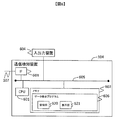
- FIG. 5 is a diagram showing the configuration of the power device 103.
- the power device 103 is a computer including a CPU 501, a memory 502, an interface 503, an input / output device 504, and a control device 505, which are connected via a communication path 506.
- the memory 502 is a storage medium that includes a program processed by the CPU 401, and includes the following programs.
- the power amount transmission program 507 is a program for transmitting the power consumption amount of the electric device.
- the operation control program 508 is a program that controls the operation of the power device 103.
- the power amount transmission program 507 stores a transmission unit 520.
- the transmission unit 520 transmits a message generated by the electric device 103.
- the operation control program 508 stores a receiving unit 521 and a control unit 522.
- the receiving unit 521 receives a control message.
- the control unit executes control of the power device 103 based on the received control message.
- the control message is a command transmitted to execute control of the power device 103, and the state of the power device 103 is changed by inputting this command.
- the power device 103 is an air conditioner
- the power supply of the air conditioner is turned on or off, or the set temperature is changed.
- An interface 503 is a communication interface for performing external communication with the data center apparatus 100.
- the interface 503 is connected to the communication path 107.
- the input / output device 504 is a device for inputting / outputting data to / from the adapter, such as a display or a remote controller.
- the control device 505 is a device for controlling a device such as a home appliance to which the power device 103 is connected. For example, assume that the home appliance is an air conditioner. When a switch ON control message is sent from the power device 103 to the control device 505, the air conditioner switch is turned ON.
- the measuring device 509 is a device that measures the amount of electricity used by the power device 103.
- FIG. 6 is a diagram showing the configuration of the display terminal 104.
- the display terminal 104 is a computer including a CPU 601, a memory 602, an interface 603, and an input / output device 604, which are connected via a communication path 605.
- the memory 602 is a storage medium that includes a program processed by the CPU 601 and includes the following programs.
- the data display program 606 is a program that displays received data.
- the data display program 606 stores a receiving unit 620 and a display unit 621.
- the receiving unit 620 receives data.
- the display unit 621 displays received data.
- An interface 603 is a communication interface for performing external communication with the display terminal 104.
- the interface 603 is connected to the communication path 107.
- the input / output device 604 is a device for inputting / outputting data to / from the display terminal, and is, for example, a display or a remote controller.
- FIG. 7 is a diagram showing the configuration of the message transmission policy DB 207.
- the message transmission policy DB 207 is a database that defines a correspondence between a network state and a message to be transmitted in that state.
- ID 701 is a unique identifier for identifying data.
- the message type 702 is a character string that describes the category of the message. For example, a message is related to “control information”.
- the transmission / reception type 703 is data indicating whether the message included in the message type is a transmission message or a reception message.
- the network state 704 is a matrix in which a flag indicating whether or not a message of a certain message type should be sent when the network state is of a certain type.
- the message type “control information” defines a policy such that it is transmitted when the network state is A, or is not transmitted when the network status is B or C (or an alternative message is transmitted). Which ID 701 is to be transmitted may be determined by a person.
- FIG. 8 is a diagram showing the configuration of the use protocol determination policy DB 208.
- the used protocol determination policy DB 208 is a database that defines which protocol is used depending on the network state.
- ID 801 is a unique identifier for identifying data.
- the network status 802 is an identifier when the network status is classified into categories.
- the used protocol 803 is a type of protocol used corresponding to the network state 802.
- the protocol used in addition to protocol types such as TCP and UDP, the protocol type in the application layer such as HTTP, the type of authentication / encryption protocol used at the time of communication, and the like are defined as necessary.
- selection of whether to use PKI authentication or ID and password authentication is specified according to the communication environment. In the following, the embodiment will be described using an example of selecting TCP and UDP on IP as an example of protocol selection.
- FIG. 9 is a diagram showing a configuration of the transmission message DB 209.
- the transmission message DB 209 is a database that stores the contents of messages to be transmitted according to the network status.
- ID 901 is a unique identifier for identifying data.
- the ID 901 corresponds to the ID 701 in the message transmission policy DB 207, and represents the same data when the identifier of the ID 901 and the identifier of the ID 701 are the same.
- the regular message 902 is a character string indicating the content of the message.
- the regular message is a message that has a significant influence on the device, such as controlling the device.
- the alternative message 903 is a character string of an alternative message to be transmitted when it is selected not to transmit the message 902.
- the substitute message is a message that has a slight influence on the device, such as sending a control request to the device.
- the reliability such as the ON / OFF control of the air conditioner switch such as using a protocol such as TCP is used. If this is not the case, use a protocol with a lighter network load than TCP, such as UDP.
- TCP Transmission Control Protocol
- UDP User Datagram Protocol
- the person who manages the air conditioner sees the message and can send a message.
- a protocol suitable for more complicated communications such as TCP is used, and sending and receiving messages that do not require much reliability.
- implementation is often performed in which communication is performed using a protocol with a lighter network load such as UDP and a light security corresponding to the protocol.
- FIG. 10 is a diagram showing the configuration of the network status DB 210.
- the network status DB 210 is a database for storing data such as the network execution transfer rate and the packet loss rate.
- the execution transfer rate is calculated from the number of packets transmitted / received per unit time by the data center device 100.
- the response time is calculated by the data center device 100 by measuring how long it takes a response (ACK response or the like) to the transmitted packet.
- ID 1001 is a unique identifier for identifying data.
- the communication destination IP address 1002 is an IP address for specifying a communication destination device that communicates with the data center apparatus 100.
- the network status 1003 is an identifier that categorizes the network status.
- the effective transfer rate 1004 is a transfer rate when the data center device 100 and the device having the communication destination IP address 1002 communicate with each other.
- the packet loss rate 1005 is a ratio of packets lost when performing the communication.
- the response time 1006 is an average response time when performing the communication.
- FIG. 11 is a diagram showing the configuration of the network status determination DB 211.
- the network status determination DB 211 is a matrix that defines conditions relating to the network status and the ranks of the network status under those conditions.
- ID 1101 is a unique identifier for identifying data.
- the network status 1102 is an identifier indicating the rank of the network status.
- the transfer speed 1103 is a condition regarding the transfer speed.
- the packet loss rate 1104 is a condition regarding the packet loss rate.
- Response time 1105 is a condition related to response time.
- the network state 1102 is defined as a rank corresponding to the condition. For example, if the item 1103 satisfies the network state A, the item 1104 satisfies the network state B, and the item 1105 satisfies the network state C, the network state C is determined as a whole.
- FIG. 12 is a flowchart showing the flow of processing of the network property collection program 212.
- the network property acquisition process 1201 is a process in which the receiving unit 220 acquires a property of communication between the data center apparatus 100 and a communication destination IP address.
- the properties here are the transfer rate, packet loss rate, and response time of communication between the data center apparatus 100 and the communication destination IP address.
- the network determination unit 221 inquires the conditions of the network status determination DB 211 from the data received, determines the network status 1102, and writes the result to the network status DB 210.
- FIG. 13 is a flowchart showing a processing flow of the message transmission program 213.
- the transmission unit 224 acquires the network state at the time when this process is executed from the network status DB 210.
- the message selection unit 222 and the protocol selection unit 223 refer to the transmission destination IP address 1002 and the network status 1003, and the protocol used when communicating with the device having the communication destination IP address 1002. Determine the message.
- the network determination unit determines a network congestion state.
- determining the network congestion state means, for example, determining whether the network state is free or congested. If it is determined that the network is free, a protocol with a high network load is selected.
- a protocol with a low network load is selected.
- communication reliability is ensured, so a regular message that is a message with a large amount of data is selected.
- a protocol with a low network load is selected, the reliability of communication is not ensured, so an alternative message that is a message with a small amount of data is selected.
- the message transmission policy DB 207 and the use protocol determination policy DB 208 are used as criteria for determination.
- the message is transmitted to the destination IP address.
- a control message is a message that directly accompanies a physical operation of an air conditioner or the like, and therefore a secure communication path with high security encryption and authentication is secured and transmitted over TCP, but the communication environment is poor.
- a control message is not a control message that directly controls, but a control recommendation message that includes only information that prompts control.
- FIG. 14 is a flowchart showing a processing flow of the data transmission / reception program 306.
- the data transmission / reception program 306 is a data reception process 1401, and the transmission / reception unit 320 outputs data received from one of the two interfaces 204 in the home server from the other interface by the data transmission process 1402. For example, the data received from the interface 204-1 is output from the interface 204-2.
- the media at the time of reception and the media at the time of transmission are different, the header information and the like are added so that the media is converted at the time of transmission.
- the media refers to the type of communication path such as Ethernet (registered trademark) connection, serial connection, or connection using a wireless protocol. That is, the data transmission / reception program 306 plays a role of relaying data. When the reception and transmission protocols are the same, the input data is simply output as it is.
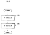
- FIG. 15 is a flowchart showing a processing flow of the data transmission / reception program 406.
- the data transmission / reception program 406 outputs the data received by the transmission / reception unit 420 from one of the two interfaces 204 in the home server in the data reception process 1501 from the other interface of the data transmission process 1502. At this time, if the protocol at the time of reception and the protocol at the time of transmission are different, the header information is added so as to comply with the protocol used at the time of transmission.
- the transmission / reception unit 421 has the same protocol at the time of reception and transmission, it simply transmits the input data.
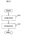
- FIG. 16 is a flowchart showing a processing flow of the electric energy transmission program 507.
- the power amount transmission program 507 calculates a power usage amount at the time when the measurement device 509 executes the program in the power amount measurement processing 1601 and transmits the power amount acquired by the processing 1601 in the power amount transmission processing 1602 to the transmission unit. 520 transmits to the data center apparatus 100.
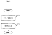
- FIG. 17 is a flowchart showing the flow of processing of the data reception program 508.
- the receiving unit 521 receives a control message input from the interface 503, analyzes the control message in a control message receiving process 1701, and transmits the control message to the control device 505 in a control execution process 1702. 522 controls the electric power device 103.
- the power device 103 is an air conditioner and a control message “switch ON” is input from the outside, this control message is interpreted by the device operation control program 507 and the switch of the air conditioner is turned “ON”.
- FIG. 18 is a flowchart showing the flow of processing of the data display program 606.
- the receiving unit 620 receives data input from the interface 603 by the data receiving process 1601.
- the display unit 621 displays the data on the input / output device 604 by the data display processing 1602.
- An example of a display destination input / output device is, for example, a television screen.
- the data center apparatus 100 and each device can be changed so as to periodically transmit and receive data. It is.
- the data in this case is set to a level that does not place a heavy load on the processing capacity of the network and each device.
- the meaning of the data content itself is not particularly limited here. As an example, data such as PING in a TCP / IP network can be considered. With this change, more accurate values can be calculated when calculating network properties.
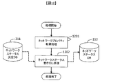
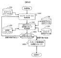
- FIG. 19 is a flowchart showing the processing flow of the message transmission program 213, which is the second embodiment of FIG. 1303 in FIG. 13 corresponds to 1903 and 1904 in FIG.
- step 1903 of FIG. 19 when it is determined that the information transmitted / received between the data center apparatus 100 and each device is the alternative message 903, the message 902 that should have been originally transmitted is temporarily stored in the memory of the transmission source. Saved in the storage device (202 or 203) (the structure of this saved data will be described later in FIG. 20), and when the network property becomes capable of sending the message 902 later, the saved messages are sent together.
- the unit 224 can also transmit.
- processes 1301 and 1302 in FIG. 19 are the same as the processes having the same numbers in FIG.
- the message transmission process 1904 is equivalent to the message transmission process 1303 in FIG. 13, but only regular messages are sent in FIG. 19.
- a message once transmitted is illustrated. Note that the data is deleted from the database described later.
- the alternative message is, for example, a control recommendation message. If the message is an alternative message in 1903, it may return to the network status acquisition process (1301) after transmitting the alternative message.
- FIG. 20 shows the configuration of the database used in the processing of FIG.
- This database stores message data to be transmitted, and once transmitted, the data is deleted. This change makes it possible to transmit a message to be sent without loss even if the network condition temporarily deteriorates.
- an embodiment in which the user sleeps for a certain period of time without sending a message and returns to the network status 1301 is possible. This change makes it possible to send the message 902 after the network state is recovered without performing an operation to load the network when the network state is bad.
Landscapes
- Engineering & Computer Science (AREA)
- Computer Security & Cryptography (AREA)
- Computer Networks & Wireless Communication (AREA)
- Signal Processing (AREA)
- Data Exchanges In Wide-Area Networks (AREA)
Abstract
Si l'environnement d'un réseau varie sensiblement en résultat d'un changement des conditions météorologiques, des communications deviennent instables. La vitesse de communication chute, et en conséquence, des communications dans le même protocole deviennent instables. Selon la présente invention, un dispositif de transmission de message servant à transmettre des données à un dispositif de réception de message est caractérisé en ce qu'il comprend une unité de réception pour recevoir des données qui comprennent des informations relatives à l'état du dispositif de réception de message relativement à un réseau, une unité d'évaluation pour évaluer l'état du dispositif de réception de message par rapport à un réseau sur la base des informations reçues relatives à l'état du réseau, une unité de sélection de protocole pour sélectionner un protocole sur la base de l'état évalué du réseau, et une unité de transmission pour transmettre les données au dispositif de réception de message avec le protocole.
Priority Applications (1)
| Application Number | Priority Date | Filing Date | Title |
|---|---|---|---|
| PCT/JP2011/000998 WO2012114371A1 (fr) | 2011-02-23 | 2011-02-23 | Dispositif de transmission de message et procédé de transmission de message |
Applications Claiming Priority (1)
| Application Number | Priority Date | Filing Date | Title |
|---|---|---|---|
| PCT/JP2011/000998 WO2012114371A1 (fr) | 2011-02-23 | 2011-02-23 | Dispositif de transmission de message et procédé de transmission de message |
Publications (1)
| Publication Number | Publication Date |
|---|---|
| WO2012114371A1 true WO2012114371A1 (fr) | 2012-08-30 |
Family
ID=46720200
Family Applications (1)
| Application Number | Title | Priority Date | Filing Date |
|---|---|---|---|
| PCT/JP2011/000998 Ceased WO2012114371A1 (fr) | 2011-02-23 | 2011-02-23 | Dispositif de transmission de message et procédé de transmission de message |
Country Status (1)
| Country | Link |
|---|---|
| WO (1) | WO2012114371A1 (fr) |
Cited By (2)
| Publication number | Priority date | Publication date | Assignee | Title |
|---|---|---|---|---|
| WO2022173020A1 (fr) * | 2021-02-12 | 2022-08-18 | 株式会社富士通ゼネラル | Climatiseur, dispositif de commande de climatisation, système de climatisation |
| CN116783431A (zh) * | 2021-02-12 | 2023-09-19 | 富士通将军股份有限公司 | 空调机、空调控制装置以及空调系统 |
Citations (2)
| Publication number | Priority date | Publication date | Assignee | Title |
|---|---|---|---|---|
| JPH0936877A (ja) * | 1995-07-21 | 1997-02-07 | Hitachi Ltd | データ通信システム |
| JP2005348262A (ja) * | 2004-06-04 | 2005-12-15 | Ricoh Co Ltd | データ通信方式、電子会議システム、データ通信方法、データ通信プログラム及び記憶媒体 |
-
2011
- 2011-02-23 WO PCT/JP2011/000998 patent/WO2012114371A1/fr not_active Ceased
Patent Citations (2)
| Publication number | Priority date | Publication date | Assignee | Title |
|---|---|---|---|---|
| JPH0936877A (ja) * | 1995-07-21 | 1997-02-07 | Hitachi Ltd | データ通信システム |
| JP2005348262A (ja) * | 2004-06-04 | 2005-12-15 | Ricoh Co Ltd | データ通信方式、電子会議システム、データ通信方法、データ通信プログラム及び記憶媒体 |
Cited By (2)
| Publication number | Priority date | Publication date | Assignee | Title |
|---|---|---|---|---|
| WO2022173020A1 (fr) * | 2021-02-12 | 2022-08-18 | 株式会社富士通ゼネラル | Climatiseur, dispositif de commande de climatisation, système de climatisation |
| CN116783431A (zh) * | 2021-02-12 | 2023-09-19 | 富士通将军股份有限公司 | 空调机、空调控制装置以及空调系统 |
Similar Documents
| Publication | Publication Date | Title |
|---|---|---|
| CN109314919B (zh) | 多接口功率感知网络 | |
| JP5865221B2 (ja) | センサデータ収集システム及びゲートウェイ制御方法 | |
| US10237807B2 (en) | System and method for mixed-mesh wireless networking | |
| CN108173938B (zh) | 服务器负载分流方法及装置 | |
| US8502640B2 (en) | System and method for transmitting and receiving information on a neighborhood area network | |
| US7941530B2 (en) | Thermostat status notification through a network | |
| Bennett et al. | Decreased time delay and security enhancement recommendations for AMI smart meter networks | |
| JP5238829B2 (ja) | データ収集装置、データ収集プログラム、およびデータ収集システム | |
| RU2013141073A (ru) | Способ и устройство для реализации дистанционного управления жилищем | |
| US20150148961A1 (en) | Building data managing apparatus and building management system comprising thereof | |
| JP5974931B2 (ja) | 通信装置 | |
| JP2016019179A (ja) | 通信装置、端末装置およびプログラム | |
| KR101926367B1 (ko) | 상이한 통신 방식의 호환성 처리를 수행하고 우선 순위에 따라 디바이스를 제어하는 IoT 브로커 서버 | |
| US11388631B2 (en) | Data reduction in a system | |
| CN107925630B (zh) | 机器对机器通信系统中的通信策略控制 | |
| US20130080994A1 (en) | Program generating apparatus, program generation method and computer readable medium | |
| WO2012114371A1 (fr) | Dispositif de transmission de message et procédé de transmission de message | |
| JP6813110B1 (ja) | 通信装置、プログラム、通信方法、及び通信システム | |
| JP6029064B2 (ja) | 通信システム、親機、サーバ | |
| JP5404943B2 (ja) | データ収集装置、データ収集プログラム、およびデータ収集システム | |
| JP6390483B2 (ja) | 制御装置、制御システムおよび制御方法 | |
| JP5135422B2 (ja) | ゲートウェイ装置 | |
| JP5915755B2 (ja) | 情報処理装置 | |
| KR101241736B1 (ko) | 포트 포워딩 설정 방법, 이를 이용한 네트워크 단말장치 및 네트워크 시스템 | |
| Begović et al. | MQTT Protocol in Smart Home Environments: Principles of Operation and Application |
Legal Events
| Date | Code | Title | Description |
|---|---|---|---|
| 121 | Ep: the epo has been informed by wipo that ep was designated in this application |
Ref document number: 11859051 Country of ref document: EP Kind code of ref document: A1 |
|
| NENP | Non-entry into the national phase |
Ref country code: DE |
|
| 122 | Ep: pct application non-entry in european phase |
Ref document number: 11859051 Country of ref document: EP Kind code of ref document: A1 |
|
| NENP | Non-entry into the national phase |
Ref country code: JP |