WO2012114377A1 - Unité de vibration - Google Patents
Unité de vibration Download PDFInfo
- Publication number
- WO2012114377A1 WO2012114377A1 PCT/JP2011/001011 JP2011001011W WO2012114377A1 WO 2012114377 A1 WO2012114377 A1 WO 2012114377A1 JP 2011001011 W JP2011001011 W JP 2011001011W WO 2012114377 A1 WO2012114377 A1 WO 2012114377A1
- Authority
- WO
- WIPO (PCT)
- Prior art keywords
- support member
- yoke
- vibration unit
- vibration
- outer peripheral
- Prior art date
- Legal status (The legal status is an assumption and is not a legal conclusion. Google has not performed a legal analysis and makes no representation as to the accuracy of the status listed.)
- Ceased
Links
Images


Classifications
-
- H—ELECTRICITY
- H04—ELECTRIC COMMUNICATION TECHNIQUE
- H04R—LOUDSPEAKERS, MICROPHONES, GRAMOPHONE PICK-UPS OR LIKE ACOUSTIC ELECTROMECHANICAL TRANSDUCERS; ELECTRIC HEARING AIDS; PUBLIC ADDRESS SYSTEMS
- H04R9/00—Transducers of moving-coil, moving-strip, or moving-wire type
- H04R9/06—Loudspeakers
-
- H—ELECTRICITY
- H04—ELECTRIC COMMUNICATION TECHNIQUE
- H04R—LOUDSPEAKERS, MICROPHONES, GRAMOPHONE PICK-UPS OR LIKE ACOUSTIC ELECTROMECHANICAL TRANSDUCERS; ELECTRIC HEARING AIDS; PUBLIC ADDRESS SYSTEMS
- H04R2400/00—Loudspeakers
- H04R2400/03—Transducers capable of generating both sound as well as tactile vibration, e.g. as used in cellular phones
-
- H—ELECTRICITY
- H04—ELECTRIC COMMUNICATION TECHNIQUE
- H04R—LOUDSPEAKERS, MICROPHONES, GRAMOPHONE PICK-UPS OR LIKE ACOUSTIC ELECTROMECHANICAL TRANSDUCERS; ELECTRIC HEARING AIDS; PUBLIC ADDRESS SYSTEMS
- H04R2460/00—Details of hearing devices, i.e. of ear- or headphones covered by H04R1/10 or H04R5/033 but not provided for in any of their subgroups, or of hearing aids covered by H04R25/00 but not provided for in any of its subgroups
- H04R2460/13—Hearing devices using bone conduction transducers
-
- H—ELECTRICITY
- H04—ELECTRIC COMMUNICATION TECHNIQUE
- H04R—LOUDSPEAKERS, MICROPHONES, GRAMOPHONE PICK-UPS OR LIKE ACOUSTIC ELECTROMECHANICAL TRANSDUCERS; ELECTRIC HEARING AIDS; PUBLIC ADDRESS SYSTEMS
- H04R5/00—Stereophonic arrangements
- H04R5/02—Spatial or constructional arrangements of loudspeakers
- H04R5/023—Spatial or constructional arrangements of loudspeakers in a chair, pillow
-
- H—ELECTRICITY
- H04—ELECTRIC COMMUNICATION TECHNIQUE
- H04R—LOUDSPEAKERS, MICROPHONES, GRAMOPHONE PICK-UPS OR LIKE ACOUSTIC ELECTROMECHANICAL TRANSDUCERS; ELECTRIC HEARING AIDS; PUBLIC ADDRESS SYSTEMS
- H04R9/00—Transducers of moving-coil, moving-strip, or moving-wire type
- H04R9/02—Details
- H04R9/025—Magnetic circuit
Definitions
- the present invention relates to a vibration unit that converts an electrical signal into mechanical vibration.
- a vibration unit for making a human feel a vibration is used as a device for obtaining a bodily sensation vibration in a low sound range.
- a vibration unit built in a chair or cushion converts an electric signal that drives a speaker that has passed through a low-pass filter into mechanical vibration and vibrates to reproduce the low-frequency body vibration.
- By driving a speaker that outputs high to low sounds together with a vibration unit it is possible to reproduce an acoustic environment where you can feel the low range richly.
- a magnetic circuit component is supported in a case by a support member, and the magnetic circuit component is vibrated by a framing law between a current of a coil attached to the case and a magnetic flux of the magnetic circuit component.
- This vibration unit is composed of a cylindrical casing connected to a built-in voice coil, a magnet, a plate that forms a magnetic gap for the voice coil, and a pole yoke that are opposed to each other with the magnet interposed therebetween.
- the magnetic circuit is arranged in a state of floating in the body, and one supporting member for supporting the magnetic circuit inside the housing is provided.
- the vibration unit needs to widen the output frequency band of the vibration unit in the low sound range in order to realize a low-frequency feel vibration. Since this type of vibration unit has one support member for the magnetic circuit, the support member must be made of a low elastic and hard material in order to maintain the magnetic gap between the coil and the magnetic circuit structure during driving. Don't be. However, if the support member is made of a hard material, the resonance frequency due to the mass and elasticity increases, and the sharpness of resonance also increases. When the resonance frequency is increased, the vibration amount of the vibration unit itself below the resonance frequency is decreased, and sufficient body vibration cannot be obtained. Further, when the resonance sharpness is high, there is a problem that the vibration increases only at the resonance frequency and the function as the vibration unit is lowered. Further, as in the vibration unit described in Patent Document 1, the operation is stabilized by providing two hard support members made of the same material on both the upper and lower sides, but this problem becomes more prominent.
- an object of the present invention is to provide a vibration unit that can extract vibrations in a wide frequency band of output.
- the vibration unit of the present invention is composed of a casing connected to the voice coil, a magnet, a plate and a yoke that confront each other with the magnet interposed therebetween, and forms a magnetic gap for the voice coil.
- a magnetic circuit disposed on the top plate side of the housing, a first support member that supports the magnetic circuit on the inner surface of the housing, and a magnetic circuit disposed on the bottom plate side of the housing.
- a second support member supported on the inner surface of the body, wherein the first support member and the second support member have different elastic and vibration transmission loss characteristics.
- vibrations in a desired wide output frequency band can be extracted while maintaining the coupling strength between the magnetic circuit and the housing. It is possible to provide a vibration unit that can perform the above operation. That is, since the vibration transmission characteristics of the two supporting members that transmit the relative vibration generated between the voice coil and the magnetic circuit to the housing are different, vibrations in a desired wide output frequency band can be taken out. .
- the above-described vibration unit is characterized in that the first support member and the second support member are formed of different materials.
- the resonance sharpness of the resonance frequency can be kept low. Further, by providing the first support member and the second support member in parallel, it is possible to prevent the vibration axis of the magnetic circuit from shaking, rolling, and excessive vibration.
- the first support member has a low elasticity and a hard characteristic that determines the resonance frequency of relative vibration generated between the voice coil and the magnetic circuit, compared to the second support member.
- the two support members are characterized by having elasticity that does not affect the resonance frequency of relative vibration generated between the voice coil and the magnetic circuit.
- This configuration eliminates the need to increase the resonance frequency so much that the frequency band of vibration to be reproduced is not narrowed.
- the above-described vibration unit is characterized in that the first support member is made of a material having lower vibration transmission loss characteristics than the second support member.
- the first support member uses a material that is hard in elasticity but has low vibration transmission loss characteristics, so that a resonance frequency of relative vibration generated between the voice coil and the magnetic circuit is mainly determined.
- the magnetic circuit can be supported while maintaining a gap with the voice coil in the magnetic gap.
- the function of the second support member serves to suppress the resonance sharpness of the resonance frequency of the magnetic circuit and stabilize the operation of the magnetic circuit.
- the above-mentioned vibration unit is characterized in that the second support member is made of an independently foamed porous resin.
- the independently foamed porous resin generates heat due to the increase in the air pressure in the bubbles accompanying the compression of the bubbles due to the bending and elongation of the second support member during vibration of the magnetic circuit (first thermodynamics). law). From this, the independently foamed porous resin can efficiently convert vibration energy into heat energy. That is, the resonance sharpness can be suppressed.
- the first support member is configured such that the outer edge portion is sandwiched between the annular first case step portion formed in the housing and the flange connecting the voice coil and the housing. It is fixed.
- the first support member and the second support member can be provided apart along the axial direction, it is possible to prevent axial blurring of the magnetic circuit and the like.
- the second support member is fixed so that the outer edge portion is sandwiched between the annular second case step portion formed in the housing and the bottom plate of the housing.
- the support member since a part of the housing is processed, it is easy to attach the support member. Furthermore, the attachment strength with respect to the movement of the magnetic circuit in the vibration direction can be increased. In addition, it is preferable that attachment of a supporting member is fixation by the adhesive agent applied to the at least outer peripheral surface of the supporting member. According to this, the peeling force to the layer of the adhesive does not work, and an attachment form that takes into account the strength of the adhesive can be obtained.
- a magnetic pole gap is formed between the inner peripheral end of the plate and the outer peripheral portion of the yoke
- the first support member includes an annular plate step portion having an inner edge portion formed on the plate, a magnet
- the second support member is fixed so that the inner edge is sandwiched between the annular yoke step formed on the yoke and the magnet.
- the support member is preferably fixed by an adhesive applied to at least the outer circumferential surface of the support member.
- a magnetic pole gap is formed between the inner peripheral end of the plate and the outer peripheral portion of the yoke, and the first support member has a first sandwiching of the inner edge portion fixed to the magnet and the outer peripheral surface of the plate.
- the second support member is fixed so that the inner edge portion is clamped between the magnet and the second clamping ring fixed to the outer peripheral surface of the yoke. It is characterized by.
- the mounting strength of the magnetic circuit against movement in the vibration direction can be increased, and the support member is clamped and fixed by the clamp ring independent of the magnetic circuit. It can be changed to one having a different thickness. Thereby, the vibration transmission characteristic of the support member can be adjusted.
- the fixing of the supporting member is preferably fixing with an adhesive applied to at least the outer peripheral surfaces of the supporting member and the holding ring.
- a magnetic pole gap is formed between the inner peripheral end of the plate and the outer peripheral portion of the yoke, the first support member is formed of resin, and the plate is a part of a molding die.
- the second support member is formed of a resin, and the yoke is a part of the mold, and is formed so as to be integrated with the yoke.
- each support member is integrated with the plate and the yoke, the magnetic circuit can be fixed with higher strength against movement in the vibration direction. Further, the first support member and the second support member can be easily formed.
- a magnetic pole gap is formed between the outer peripheral end of the plate and the inner peripheral wall portion of the yoke
- the first support member is an annular first yoke having an inner edge portion formed on the outer peripheral wall portion of the yoke.
- the second support member is fixed so as to be clamped between the stepped portion and the first clamping ring fixed to the first yoke stepped portion, and the second support member has an annular first shape formed on the outer peripheral wall portion of the yoke. It is fixed so that it may be clamped between the 2 yoke step part and the 2nd clamping ring fixed to the 2nd yoke step part.
- the vibration unit can be reduced in size in the extending direction of the support member.
- the mounting strength of the magnetic circuit with respect to movement in the vibration direction can be increased.
- the fixing of the supporting member is preferably an adhesive fixing with an adhesive applied to at least the inner peripheral surfaces of the supporting member and the holding ring.
- the support member since the support member is clamped and fixed by a clamp ring independent of the magnetic circuit, the support member can be changed to one having a different thickness. Thereby, the vibration transmission characteristic of the support member can be adjusted.
- a magnetic pole gap is formed between the outer peripheral end of the plate and the inner peripheral wall portion of the yoke
- the first support member is an annular yoke step portion in which the inner edge portion is formed at the upper portion of the outer peripheral wall of the yoke.
- the spacer ring fixed to the outer peripheral wall portion of the yoke, and the second support member includes the spacer ring and the holding ring fixed to the outer peripheral wall portion of the yoke. It is fixed so that it may be pinched
- the attachment of the support member is preferably fixed by an adhesive applied to the inner peripheral surfaces of the support member, the spacer ring, and the holding ring.
- the above-described vibration unit is characterized in that the first support member and the spacer ring are made of resin, and the yoke is part of a molding die and is integrally formed with the yoke.
- the above-described vibration unit is characterized in that the second support member has a plurality of communication holes that communicate the space on the outer peripheral side of the magnet and the space on the bottom plate side.
- the side surface and the bottom surface of the magnetic circuit are cooled by the high-speed inflow of air between the space on the magnet outer periphery side and the space on the bottom plate side due to the vibration of the magnetic circuit, and the magnetic circuit can be cooled.
- the input tolerance of a voice coil can be enlarged.
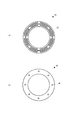
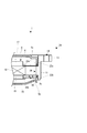
- FIG. 10 is an enlarged side view around a support member of a vibration unit according to a third embodiment. It is the top view (a) and sectional drawing (b) of the vibration unit concerning 4th Embodiment. It is an enlarged side view around the support member of the vibration unit concerning 4th Embodiment.
- FIG. 10 is an enlarged side view around a support member of a vibration unit according to a fifth embodiment. It is an enlarged side view around a support member of a vibration unit concerning a 6th embodiment.
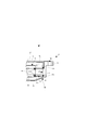
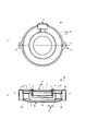
- the vibration unit 1 includes a shallow cylindrical case 2 (housing) composed of an upper case 2a and a lower case 2b, and an annular voice coil connected to the upper case 2a in the case 2 3, a magnetic circuit 4 on a disc built in the case 2, and a pair of annular support members 5 that support the magnetic circuit 4 in a floating state in the case 2.
- the upper case 2 a is composed of a disk-shaped flange 8 and an annular side wall 11. As shown in FIG. 1A, the flange 8 is formed with a conducting wire passage 12 through which a conducting wire for allowing a signal current to flow through the voice coil 3 is passed.
- the side wall 11 has an annular mounting piece 13 provided on the same surface as the flange 8 so as to protrude to the outer peripheral side.
- the attachment piece 13 has an attachment hole 14 through which a plurality of screws for attaching the vibration unit 1 are inserted into a vibration transmission object to which vibration is transmitted from the vibration unit 1.
- the lower case 2 b has a bottom plate 15 and is formed in a gentle mortar shape so that a space exists between the bottom surface of the magnetic circuit 4 and the bottom plate 15.
- the magnetic circuit 4 includes a pole yoke 16 disposed on the lower case 2b side and a disc annular plate disposed on the upper case 2a side on the same axis as the case 2. 17 and a disc yoke 18 and a disc-shaped magnet 18 sandwiched between the plate 17 and the plate 17.
- an outer magnet type vibration unit will be described.
- the yoke becomes the pole yoke 16.
- the pole yoke 16 is made of a magnetic material, and has a disc-shaped flange-shaped portion 16a that faces the plate 17 with the magnet 18 interposed therebetween, and projects from the center of the flange-shaped portion 16a. And a columnar pole portion 16b penetrating therethrough.
- the hook-shaped portion 16a has a first pole yoke step portion 21a that engages with the inner edge portion of the magnet 18, and a second pole yoke step portion 21b that engages with an inner edge portion of the second support member 5b described later.
- the magnet 18 may be composed of a neo-geo magnet or a ferrite magnet.
- a lower portion of the inner diameter of the magnet 18 is engaged with the first pole yoke step portion 21 a of the pole yoke 16.
- the inner diameter of the magnet 18 is configured to be larger than the outer shape of the pole portion 16b.
- the plate 17 is made of a magnetic material and has an inner diameter that is larger than the outer shape of the pole portion 16b.
- a magnetic gap 6 is formed between the inner peripheral surface of the plate 17 and the outer peripheral surface of the pole portion 16b.
- a center cap 7 is disposed on the upper coaxial side of the pole portion 16b so that dust does not enter the case 2.
- the voice coil 3 is wound in a floating state around a magnetic gap 6 formed by a pole portion 16b and a plate 17, and has an annular portion provided along the inner side of the side wall 11 of the upper case 2a and a flange having a top plate portion at the center thereof. 8 is connected to the upper case 2a.
- the support member 5 includes a first support member 5a that supports the magnetic circuit 4 on the flange 8 side, and a second support member 5b that supports the magnetic circuit on the bottom plate 15 side.
- the vibration unit 1 can transmit vibration according to the signal current transmitted to the voice coil 3 to the vibration transmission object.
- the first support member 5 a has an outer edge portion fixed between an annular first case step portion 22 a formed on the inner surface of the side wall 11 of the upper case 2 a and an end portion of the flange 8.
- the inner edge portion is sandwiched and fixed between the upper surface of the magnet 18 and the plate step portion 23 formed on the outer peripheral side of the bottom surface of the plate 17.
- the second support member 5b has an outer edge portion sandwiched and fixed between an annular second case step portion 22b formed on the inner surface of the side wall 11 of the lower case 2b and the end portion of the bottom plate 15, and has an inner edge.
- the portion is sandwiched and fixed between the lower surface of the magnet 18 and the second pole yoke step portion 21 b formed on the flange-shaped portion 16 a of the pole yoke 16. That is, the first support member 5a and the second support member 5b have the thickness of the case protrusion 24 constituted by the first case step 22a and the second case step 22b at the outer edge, and the thickness of the magnet 18 at the inner edge.
- the case 2 is disposed at a position separated in the thickness direction of the case 2.
- the case protrusion 24 and the magnet 18 are formed to have the same thickness, and the first support member 5a and the second support member 5b are arranged in parallel.
- each support member 5 is sandwiched and attached to each member so that the outer edge portion is inserted into the case 2 and the inner edge portion is inserted into the magnetic circuit 4, the attachment strength against the force in the vibration direction. Can be increased. Moreover, the damage by the deformation
- the first support member 5a and the second support member 5b are fixed by an adhesive applied to the inner peripheral surface, the outer peripheral surface, the inner peripheral side of the upper surface and the lower surface, and the outer peripheral side.
- the adhesive applied to the inner peripheral surface and the outer peripheral surface is not peeled off in the vibration direction applied to each support member when the vibration unit 1 is driven, and attachment with higher strength in the vibration direction can be performed. it can.
- the vibration characteristics of the magnetic circuit 4 can be adjusted by the shape, material and thickness of each support member 5.
- the first support member 5a is formed by punching a metal plate into an annular shape.
- the first support member 5a has a plurality of buffer holes 25 for adjusting the elasticity thereof.
- the first support member 5 a is attached to the flange 8 side of the case 2 and holds the center of the magnetic circuit 4 in order to always maintain a gap with the voice coil 3 in the magnetic gap 6.
- the material constituting the first support member 5a is preferably a hard material with little vibration loss. You may comprise hard resin other than a metal.
- the first support member 5a functions as a main elastic suspension of resonance generated by the relative vibration generated between the voice coil 3 and the magnetic circuit 4, but is more than necessary due to the function of the pair of support members. Therefore, it is not necessary to use a hard elastic material, so that the resonance frequency can be lowered.
- the second support member 5b is made of a sheet-like resin.
- the loss of the second support member 5b is adjusted by its thickness and material. Since the second support member 5b is attached to the bottom plate 15 side of the case 2 and is mainly intended to prevent the lateral blur of the magnetic circuit 4, the constituent material does not need to be as hard as the first support member 5a, and the loss is reduced. Consists of a large soft resin.
- the second support member 5b is made of an independently foamed porous resin in order to prevent fluctuations in transmission loss due to the temperature of the soft resin.
- the bubbles are compressed by the bending and extension of the second support member 5b when the magnetic circuit 4 vibrates, and the pressure inside the bubbles increases to generate heat (the first law of thermodynamics). Since it can be efficiently converted into energy, fluctuations in the amount of transmission loss due to temperature can be suppressed.
- the second support member 5b can be made of a soft elastic material, the resonance frequency of the vibration unit 1 is not increased so much. As a result, it is possible to obtain vibrations in the vibration transmission object in a wide frequency band. Moreover, the resonance sharpness of the vibration unit 1 can be lowered by configuring the second support member 5b with a soft material having a high loss. As a result, excessive vibration at the resonance frequency is suppressed, and vibration in a wide output frequency band can be extracted.
- the second support member 5b has a plurality of communication holes 40 that allow the space on the outer peripheral side of the magnet 18 to communicate with the space on the bottom plate 15 side.
- the vibration unit 1 when the vibration unit 1 is driven, heat generated in the case 2 is caused by vibration of the magnetic circuit 4, and high-speed air flows into the space on the outer peripheral side of the magnet 18 and the space on the bottom plate 15 side through the communication hole 40. Since the side and bottom surfaces are cooled and the magnetic circuit 4 can be cooled, the input resistance of the voice coil 3 can be increased.
- the communication holes 40 are desirably formed with the minimum number and size that do not affect the elasticity of the second support member 5b but obtain a high-speed air flow.
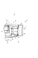
- the vibration unit 1 according to the second embodiment of the present invention is formed such that the outer diameter of the plate 17 and the outer diameter of the flange-shaped portion 16 a of the pole yoke 16 are smaller than the outer diameter of the magnet 18. Yes.
- the inner edge portion of the first support member 5 a is sandwiched and fixed between the upper surface of the magnet 18 and the first sandwiching ring 26 a bonded to the outer peripheral surface of the plate 17.
- the inner edge portion of the second support member 5b is sandwiched and fixed between the lower surface of the magnet 18 and the second sandwiching ring 26b that is bonded and fixed to the outer peripheral surface of the flange-shaped portion 16a of the pole yoke 16.
- each clamping ring 26 is independent of the component of the magnetic circuit 4, it becomes possible to change the thickness of each support member 5 and to adjust to a desired vibration transmission characteristic.
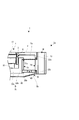
- the vibration unit 1 As shown in FIG. 5, the vibration unit 1 according to the third embodiment of the present invention is formed such that the outer diameter of the plate 17 and the outer diameter of the hook-shaped portion 16 a of the pole yoke 16 are smaller than the outer diameter of the magnet 18.
- the plate 17 is provided with a plate retaining member 27 and the pole yoke 16 is provided with a pole yoke retaining member 28 on the outer surface of the flange 16a.
- the first support member 5a includes a first retaining protrusion 30a that is integrally fixed to the plate retaining member 27, and a first outer ring portion that is sandwiched and fixed between the first case step portion 22a and the end of the flange 8.
- the second support member 5b includes a second retaining protrusion 30b that is integrally fixed to the pole yoke retaining member 28, a second outer periphery that is sandwiched and fixed between the second case step 22b and the end of the bottom plate 15. It has the ring part 31b and the 2nd arm part 32b which connects the 2nd prevention protrusion part 30b and the 2nd outer periphery ring part 31b.
- the first support member 5a of the present embodiment is made of a hard resin, and the first retaining protrusion 30a and the plate retaining member 27 are integrated with the plate retaining member 27 of the plate 17 as a part of the mold. Formed as follows.
- the second support member 5b is made of a soft resin, and the pole yoke retaining portion 28 is formed as a part of the forming mold so that the second retaining protrusion 30b and the pole yoke retaining portion 28 are integrated. Is done.
- the magnetic circuit 4 and each support member 5 can be fixed with high strength. Further, because of the integral formation, the support member 5 can be easily fixed with fewer work steps.
- first retaining protrusion 30a and the first outer ring part 31a are formed to be thicker than the first arm part 32a.
- second retaining protrusion 30b and the second outer peripheral ring portion 31b are formed thicker than the second arm portion 32b. Since the first arm portion 32 a and the second arm portion 32 b are portions that bear the elastic characteristics of the support members 5, the adhesive that has flowed out from the ring portions 31 fixed by the adhesive material is applied to the arm portions 32. Thus, it is possible to prevent the elastic characteristics of the arm portion 32 from changing.
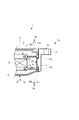
- the vibration unit 1 according to the fourth embodiment of the present invention is different from the first to third embodiments of the outer magnet type in which the magnet 18 is exposed on the outer periphery of the magnetic circuit 4.
- the yoke 16 formed in a shape is an inner magnet type that covers the outer periphery of the magnet 18.
- the vibration unit 1 according to the first to third embodiments shows an example of an outer magnet type and is expressed as a pole yoke 16.
- the fourth embodiment shows an example of an inner magnet type and is expressed as a yoke 16. Use the same symbols to describe the text.
- the magnetic circuit 4 includes a plate-shaped yoke 16 disposed on the lower case 2b side, a disk-shaped plate 17 disposed on the upper case 2a side, a yoke 16 and a plate 17 on the same axis as the case 2. And a disk-shaped magnet 18 sandwiched between the two.
- the yoke 16 has a disk-shaped bottom surface portion 33a facing the plate 17 with the magnet 18 interposed therebetween, and an annular outer peripheral wall portion 33b provided continuously from the outer periphery of the bottom surface portion 33a.
- the outer peripheral wall portion 33b includes a first yoke step portion 21a that engages with the inner edge portion of the first support member 5a, and a second yoke step portion 21b that engages with the inner edge portion of the second support member 5b.
- the magnet 18 is configured so that the outer diameter is smaller than the inner diameter of the outer peripheral wall portion 33 b of the yoke body 16.
- the plate 17 is configured such that the outer diameter is smaller than the inner diameter of the outer peripheral wall portion 33b of the yoke body 16, and a magnetic gap 6 is formed between the outer peripheral surface of the plate 17 and the inner peripheral surface of the outer peripheral wall portion 33b of the yoke 16. Is formed.
- a center cap 7 is disposed on the upper coaxial side of the plate 17 so that dust does not enter the case 2.
- the first support member 5a has its inner edge portion sandwiched and fixed between the first yoke step portion 21a and the first holding ring 26a fixed to the first yoke step portion 21a.
- the second support member 5b is sandwiched and fixed between the second yoke step portion 21b and the second holding ring 26b fixed to the second yoke step portion 21b. That is, the first support member 5a and the second support member 5b are separated from each other in the thickness direction of the case 2 by the thickness of the yoke protrusion 34 formed by the first yoke step 21a and the second yoke step 21b at the inner edge. Arranged at different positions.
- the vibration unit 1 can be downsized as a whole.
- the attachment strength in the vibration direction is increased, and each clamping ring 26 is independent of the components of the magnetic circuit 4, so that the thickness of each support member 5 is changed and adjusted to a desired vibration transmission characteristic. Is possible.
- the first yoke step portion 21 a that engages with the inner edge portion of the first support member 5 a is formed on the outer peripheral wall portion 33 b of the yoke 16.
- a spacer ring 35 is provided on the outer periphery of the outer peripheral wall portion 33 b of the yoke 16.
- the first support member 5 a has an inner edge portion fixed between the first yoke step portion 21 a and the spacer ring 35.
- the second support member 5b is clamped and fixed at the inner edge between the spacer ring 35 and the second clamping ring 26b fixed to the outer peripheral wall 33b of the yoke 16.
- the vibration unit 1 has a yoke retaining member 28 on the outer peripheral wall 33 b of the yoke 16.
- the first support member 5 a includes a first retaining protrusion 30 a that is integrally fixed to the yoke retaining portion 28, and an annular first spacer portion 36 a that extends from the first retaining protrusion 30 a to the outer peripheral wall portion 33 b of the yoke 16.
- an annular second spacer portion 36b that extends from the first case step portion 22a along the inner peripheral surface of the case 2, and an arm portion 37 that connects the upper ends of the first retaining protrusion 30a and the second spacer portion 36b.
- the first support member 5a of the present embodiment is made of a hard resin, and the first retaining protrusion 30a and the yoke retaining member 28 are integrated with the yoke retaining member 28 of the yoke 16 as a part of the mold. Formed as follows. At this time, the first spacer portion 36a and the second spacer portion 36b are also formed at a time. Thus, by forming the first support member 5a integrally with the yoke 16, the magnetic circuit 4 and the support member 5a can be fixed with high strength. In addition, because of the integral formation, the supporting member 5a can be easily fixed with fewer work steps.
- the second support member 5 b is sandwiched between the first spacer portion 36 a and the sandwiching ring 26 b that is fixed to the outer peripheral wall portion 33 b of the yoke 16.
- the second support member 5b is made of a soft material having a vibration loss higher than that of the first support member 5a, and the elasticity of the first support member does not become harder than necessary. Therefore, the resonance frequency of the vibration unit 1 can be lowered and the resonance sharpness can be suppressed. Thereby, it is possible to extract sufficient vibrations and to extract vibrations in a wide output frequency band.
- the vibration unit 1 of the present invention includes a pillow, a chair, a cushion, and the like.
- a sensory sound drive unit a vibration drive unit, a massage drive unit, and a sound generation vibration drive unit.
- a vibration drive unit a vibration drive unit
- a massage drive unit a sound generation vibration drive unit.
- a sound generation vibration drive unit by supplementing the bodily sensation with vibration, it is possible to realize an acoustic unit that can feel the bass richly at a low volume. According to this, it can contribute to a noise problem.
- Vibration unit 2 Case 2a: Upper case 2b: Lower case 3: Voice coil 4: Magnetic circuit 5a: First support member 5b: Second support member 6: Magnetic gap 8: Flange 15: Bottom plate 16: Yoke 17: Plate 18: Magnet 21a: First yoke step 21b: Second yoke step 22a: First case step 22b: Second case step 23: Plate step 26a: First holding ring 26b: Second holding ring 27 : Plate retaining part 28: Yoke retaining part 30a: First retaining protrusion 30b: Second retaining protrusion 35: Spacer ring 40: Communication hole
Landscapes
- Physics & Mathematics (AREA)
- Engineering & Computer Science (AREA)
- Acoustics & Sound (AREA)
- Signal Processing (AREA)
- Apparatuses For Generation Of Mechanical Vibrations (AREA)
Abstract
La présente invention vise à fournir une unité de vibration capable de produire une vibration ayant une large plage de fréquences de sortie. Cette unité de vibration (1) est configurée à partir d'un boîtier cylindrique (2) connecté à une bobine acoustique (3), et à partir d'une plaque (17) et d'une culasse (16) se faisant face pour enserrer les aimants (18) et constituant un entrefer magnétique annulaire (6) pour la bobine acoustique (3). En outre, l'unité de vibration (1) est caractérisée en ce qu'elle est équipée d'un circuit magnétique (4) agencée pour être élevée à l'intérieur du boîtier selon le même axe, d'un premier élément de support (5a) disposé sur le côté de la plaque supérieure du boîtier et pour assurer le support du circuit magnétique sur la face interne du boîtier, et d'un second élément de support (5b) disposé sur le côté de la plaque inférieure du boîtier et pour assurer le support du circuit magnétique sur la face interne du boîtier, le premier élément de support (5a) et le second élément de support (5b) étant caractérisés en ce qu'ils présentent une élasticité différente et une propriété différente pour la perte de transfert de vibration.
Priority Applications (1)
| Application Number | Priority Date | Filing Date | Title |
|---|---|---|---|
| PCT/JP2011/001011 WO2012114377A1 (fr) | 2011-02-23 | 2011-02-23 | Unité de vibration |
Applications Claiming Priority (1)
| Application Number | Priority Date | Filing Date | Title |
|---|---|---|---|
| PCT/JP2011/001011 WO2012114377A1 (fr) | 2011-02-23 | 2011-02-23 | Unité de vibration |
Publications (1)
| Publication Number | Publication Date |
|---|---|
| WO2012114377A1 true WO2012114377A1 (fr) | 2012-08-30 |
Family
ID=46720204
Family Applications (1)
| Application Number | Title | Priority Date | Filing Date |
|---|---|---|---|
| PCT/JP2011/001011 Ceased WO2012114377A1 (fr) | 2011-02-23 | 2011-02-23 | Unité de vibration |
Country Status (1)
| Country | Link |
|---|---|
| WO (1) | WO2012114377A1 (fr) |
Cited By (1)
| Publication number | Priority date | Publication date | Assignee | Title |
|---|---|---|---|---|
| JP2020014076A (ja) * | 2018-07-17 | 2020-01-23 | ヤマハ株式会社 | 電気音響変換装置 |
Citations (2)
| Publication number | Priority date | Publication date | Assignee | Title |
|---|---|---|---|---|
| JPS6121699A (ja) * | 1984-07-10 | 1986-01-30 | Pioneer Electronic Corp | 体感音響振動装置 |
| WO2002069669A1 (fr) * | 2001-02-26 | 2002-09-06 | Uetax Corporation | Microphone |
-
2011
- 2011-02-23 WO PCT/JP2011/001011 patent/WO2012114377A1/fr not_active Ceased
Patent Citations (2)
| Publication number | Priority date | Publication date | Assignee | Title |
|---|---|---|---|---|
| JPS6121699A (ja) * | 1984-07-10 | 1986-01-30 | Pioneer Electronic Corp | 体感音響振動装置 |
| WO2002069669A1 (fr) * | 2001-02-26 | 2002-09-06 | Uetax Corporation | Microphone |
Cited By (2)
| Publication number | Priority date | Publication date | Assignee | Title |
|---|---|---|---|---|
| JP2020014076A (ja) * | 2018-07-17 | 2020-01-23 | ヤマハ株式会社 | 電気音響変換装置 |
| JP7091900B2 (ja) | 2018-07-17 | 2022-06-28 | ヤマハ株式会社 | 電気音響変換装置 |
Similar Documents
| Publication | Publication Date | Title |
|---|---|---|
| US10206027B2 (en) | Speakers and headphones related to vibrations in an audio system, and methods for operating same | |
| CN112840674B (zh) | 与音频转换器相关的系统方法和设备 | |
| CN109862486B (zh) | 一种扬声组件 | |
| US20110243364A1 (en) | Structure of loudspeaker for reducing thickness and mounting depth | |
| WO2015040832A1 (fr) | Haut-parleur à conduction osseuse et dispositif de récepteur à conduction osseuse | |
| JPWO2004006620A1 (ja) | 電気音響変換器 | |
| EP2512153B1 (fr) | Ensemble d'aimant de haut-parleur | |
| JP6363792B2 (ja) | 電気音響変換装置 | |
| EP2512154B1 (fr) | Aimant de haut-parleur doté d'un canal | |
| WO2013114872A1 (fr) | Haut-parleur, casque d'écoute de l'oreille interne fourni avec un haut-parleur et une prothèse auditive | |
| JP5700704B2 (ja) | スピーカ装置 | |
| JP4580025B1 (ja) | 骨伝導トランスデューサ | |
| CN207369288U (zh) | 一种一体化设计的骨传导驱动器 | |
| US10484788B1 (en) | Acoustic transducer with passive diaphragm spatially integrated with active diaphragm | |
| US20100092011A1 (en) | Membrane for an electroacoustic transducer and acoustic device | |
| CN110178383A (zh) | 桥型边缘方式的高分辨率电磁扬声器 | |
| JP2011119913A (ja) | ハイブリッド型スピーカーユニットおよびハイブリッド型スピーカー | |
| WO2018003394A1 (fr) | Excitateur de vibrations | |
| JP5618420B2 (ja) | 電気音響変換器 | |
| JP4792137B1 (ja) | 振動ユニット | |
| US12375857B2 (en) | Highly compliant miniature transducer | |
| KR100769885B1 (ko) | 전자음향변환기 | |
| EP1133894A1 (fr) | Haut-parleur acoustique haute fidelite a large bande | |
| JP2007243659A (ja) | ボイスコイルボビン、およびスピーカ装置 | |
| JP6436530B2 (ja) | 動電型電気音響変換器及びその製造方法 |
Legal Events
| Date | Code | Title | Description |
|---|---|---|---|
| 121 | Ep: the epo has been informed by wipo that ep was designated in this application |
Ref document number: 11859086 Country of ref document: EP Kind code of ref document: A1 |
|
| NENP | Non-entry into the national phase |
Ref country code: DE |
|
| 122 | Ep: pct application non-entry in european phase |
Ref document number: 11859086 Country of ref document: EP Kind code of ref document: A1 |
|
| NENP | Non-entry into the national phase |
Ref country code: JP |