WO2012114380A1 - Capteur de cliquetis - Google Patents
Capteur de cliquetis Download PDFInfo
- Publication number
- WO2012114380A1 WO2012114380A1 PCT/JP2011/001056 JP2011001056W WO2012114380A1 WO 2012114380 A1 WO2012114380 A1 WO 2012114380A1 JP 2011001056 W JP2011001056 W JP 2011001056W WO 2012114380 A1 WO2012114380 A1 WO 2012114380A1
- Authority
- WO
- WIPO (PCT)
- Prior art keywords
- insulating plate
- knocking sensor
- electrode plate
- sensor
- piezoelectric element
- Prior art date
- Legal status (The legal status is an assumption and is not a legal conclusion. Google has not performed a legal analysis and makes no representation as to the accuracy of the status listed.)
- Ceased
Links
Images


Classifications
-
- G—PHYSICS
- G01—MEASURING; TESTING
- G01L—MEASURING FORCE, STRESS, TORQUE, WORK, MECHANICAL POWER, MECHANICAL EFFICIENCY, OR FLUID PRESSURE
- G01L23/00—Devices or apparatus for measuring or indicating or recording rapid changes, such as oscillations, in the pressure of steam, gas, or liquid; Indicators for determining work or energy of steam, internal-combustion, or other fluid-pressure engines from the condition of the working fluid
- G01L23/22—Devices or apparatus for measuring or indicating or recording rapid changes, such as oscillations, in the pressure of steam, gas, or liquid; Indicators for determining work or energy of steam, internal-combustion, or other fluid-pressure engines from the condition of the working fluid for detecting or indicating knocks in internal-combustion engines; Units comprising pressure-sensitive members combined with ignitors for firing internal-combustion engines
- G01L23/221—Devices or apparatus for measuring or indicating or recording rapid changes, such as oscillations, in the pressure of steam, gas, or liquid; Indicators for determining work or energy of steam, internal-combustion, or other fluid-pressure engines from the condition of the working fluid for detecting or indicating knocks in internal-combustion engines; Units comprising pressure-sensitive members combined with ignitors for firing internal-combustion engines for detecting or indicating knocks in internal combustion engines
- G01L23/222—Devices or apparatus for measuring or indicating or recording rapid changes, such as oscillations, in the pressure of steam, gas, or liquid; Indicators for determining work or energy of steam, internal-combustion, or other fluid-pressure engines from the condition of the working fluid for detecting or indicating knocks in internal-combustion engines; Units comprising pressure-sensitive members combined with ignitors for firing internal-combustion engines for detecting or indicating knocks in internal combustion engines using piezoelectric devices
-
- G—PHYSICS
- G01—MEASURING; TESTING
- G01L—MEASURING FORCE, STRESS, TORQUE, WORK, MECHANICAL POWER, MECHANICAL EFFICIENCY, OR FLUID PRESSURE
- G01L19/00—Details of, or accessories for, apparatus for measuring steady or quasi-steady pressure of a fluent medium insofar as such details or accessories are not special to particular types of pressure gauges
- G01L19/06—Means for preventing overload or deleterious influence of the measured medium on the measuring device or vice versa
- G01L19/0681—Protection against excessive heat
-
- G—PHYSICS
- G01—MEASURING; TESTING
- G01L—MEASURING FORCE, STRESS, TORQUE, WORK, MECHANICAL POWER, MECHANICAL EFFICIENCY, OR FLUID PRESSURE
- G01L19/00—Details of, or accessories for, apparatus for measuring steady or quasi-steady pressure of a fluent medium insofar as such details or accessories are not special to particular types of pressure gauges
- G01L19/14—Housings
- G01L19/141—Monolithic housings, e.g. molded or one-piece housings
Definitions
- the present invention relates to a knocking sensor using a piezoelectric element.
- a knocking sensor that detects a knocking phenomenon of an internal combustion engine such as an automobile is known, and retarding control of the ignition timing of the spark plug is performed according to the detection of the knocking sensor.
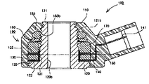
- This knocking sensor 100 is a so-called center-hole type non-resonant knocking sensor having a mounting hole 120b for mounting to a cylinder block of an internal combustion engine at the center.
- the knocking sensor 100 includes a metal shell 120 having a cylindrical part 121 and a flange part 122 positioned at the lower end of the cylindrical part 121.
- a metal shell 120 having a cylindrical part 121 and a flange part 122 positioned at the lower end of the cylindrical part 121.
- an annular lower insulating plate 130, lower electrode plate 140, piezoelectric element 150, upper electrode plate 160, upper insulating plate 135, weight 170, and A disc spring 180 is fitted.
- upper and lower terminals 141 and 161 for taking out voltages respectively extend in a piece shape.
- a male screw part 121 b is formed on the upper outer peripheral surface of the cylindrical part 121, while a female screw part 185 b is formed on the inner surface of the nut 185. Then, by screwing the nut 185 into the male screw portion 121b, the laminated body from the lower insulating plate 130 to the disc spring 180 is sandwiched and fixed between the flange portion 122 and the nut 185, and the sensor body 190 is fixed. (See FIG. 5). And as shown in FIG. 5, the sensor main body 190 is coat
- the knocking sensor 100 having such a configuration, the lower surface of the flange portion 122 of the metal shell 120 is attached so as to be in contact with the cylinder block, so that the metal shell 120 is electrically connected to the cylinder block ( The weight 170 that is electrically connected to the metal shell 120 is also electrically connected (contacted) to the cylinder block as a result. Therefore, in the knocking sensor 100, the lower insulating plate 140, the upper electrode plate 160, and the weight 170 that electrically insulate the flange portion 122 of the metal shell 120 and the lower electrode plate 140 are used as components of the sensor body 190.
- the upper insulating plate 135 that is electrically insulated is used to secure insulation of the piezoelectric element 150 with respect to the metal shell 120 and the weight 170.
- a cylindrical insulating sleeve 131 is fitted on the outer peripheral surface of the cylindrical portion 121 to prevent the lower electrode 140, the piezoelectric element 150, and the upper electrode 160 from being electrically connected to the cylindrical portion 121. ing.
- the operating temperature of the knocking sensor is about 130 ° C.
- the operating temperature of the knocking sensor is required to be 150 ° C. or higher.
- the insulation resistance of the knocking sensor is determined by the surface resistance of the resin molded body 110 and the thickness of the lower insulating plate 130 and the upper insulating plate 135 (in other words, volume resistance). There was found. That is, the phenomenon in which the insulation resistance of the knocking sensor 100 decreases as the temperature rises is viewed between the flange 122 of the metal shell 120 and the lower electrode plate 140 in the thickness direction of the lower insulating plate 130 (lower insulating plate).
- the surface is not a thickness direction, but a surface becomes a conduction path, and the surface resistance is an object that influences the insulation characteristics.
- the resin molded body 110 is required to be moldable and has a size restriction as a knocking sensor, it is necessary to select a resin material and set dimensions in consideration of the size, and the surface of the resin molded body 110 is required. It is not easy to increase resistance. Therefore, in order to increase the insulation resistance of the knocking sensor as a whole and enable use at a high temperature of 150 ° C., the surface resistivity of the resin molded body 110 itself at a high temperature is increased, It is important to increase the surface resistance.
- an object of the present invention is to provide a knocking sensor that has good insulation characteristics even at a use temperature of 150 ° C. or higher and excellent knocking detection characteristics.
- the knocking sensor of the present invention is fitted to the outer periphery of the cylindrical part, a metal shell including a cylindrical part and a flange part that is located at one end of the cylindrical part and protrudes radially outward.
- a knocking sensor comprising: a sensor main body having an upper insulating plate that electrically insulates the upper electrode plate and the weight; and a resin-made resin body that covers the sensor main body, wherein the upper insulating plate And the lower insulating plate has a thickness.
- the resin molded body, polyphenylene sulfide, or a knock sensor comprising a copolymer of tetrafluoroethylene and ethylene.
- the resin molded body covering the sensor main body is made of polyphenylene sulfide or a copolymer of tetrafluoroethylene and ethylene having good moldability and heat resistance.
- These polyphenylene sulfides and copolymers of tetrafluoroethylene and ethylene have a high surface resistivity at room temperature, and a surface resistivity at 150 ° C. of 1.0 ⁇ 10 10 ⁇ (or ⁇ / q) or more. .
- the insulation resistance of the knocking sensor can be increased as a whole.
- the resin molded body is made of the specific material, it is not necessary to excessively increase the thickness of the upper insulating plate and the lower insulating plate as described above.
- the thickness can be suppressed to 0.50 mm or less. Therefore, according to the present invention, a knocking sensor excellent in knocking detection accuracy can be obtained without deteriorating the frequency characteristics of the knocking sensor while being highly insulated.
- the thickness of the upper insulating plate and the lower insulating plate is 0.05 mm or more. This is because even if the surface resistivity of the resin molded body itself is increased, the insulation resistance of the knocking sensor cannot be maintained high as a whole if the volume resistance of the insulating plate itself decreases.
- a general-purpose resin material for example, PET
- FIG. 1 is a cross-sectional view of a knocking sensor 10 according to an embodiment of the present invention.
- a knocking sensor 10 is a so-called center-hole type non-resonant knocking sensor having a mounting hole 12f for mounting on a cylinder block of an internal combustion engine at the center.
- the knocking sensor 10 is configured by covering a sensor body 20 to be described later in detail with a resin molded body 11, and is formed into a short cylindrical shape as a whole, and the connector portion 11b is radially outward from a part of the outer periphery of the cylinder. It protrudes.
- a first terminal 14a and a second terminal 16a extending from the lower electrode 14 and the upper electrode 16 respectively project from the inner side of the connector portion 11b (only the first terminal 14a is shown in FIG. 1) and are connected to an external connector (not shown). It is like that.
- the knocking sensor 10 includes a metallic metal shell 12 having a cylindrical portion 12a and a flange portion 12b positioned at the lower end of the cylindrical portion 12a. .
- a metallic metal shell 12 having a cylindrical portion 12a and a flange portion 12b positioned at the lower end of the cylindrical portion 12a.
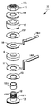
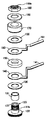
- an annular lower insulating plate 13, a lower electrode 14, a piezoelectric element 15, an upper electrode 16, an upper insulating plate 13t, a weight 17 and a disc spring are sequentially provided from the flange 12b side. 18 is fitted, and the lower insulating plate 13 is placed on the flange 12b.
- a male screw portion 12 x is formed on the upper outer peripheral surface of the cylindrical portion 12 a, while a female screw portion 19 y is formed on the inner surface of the nut 19.
- the laminated body from the lower insulating plate 13 to the disc spring 18 is sandwiched and fixed between the flange portion 12b and the nut 19, and the sensor body 20 is fixed. It is composed.
- a cylindrical insulating sleeve 13s is fitted on the outer peripheral surface of the cylindrical portion 12a to prevent the lower electrode 14, the piezoelectric element 15 and the upper electrode 16 from being electrically connected (contacted) to the cylindrical portion 12a. is doing.
- the lower insulating plate 13 is a member for preventing electrical connection (contact) between the upper surface of the flange 12b of the metal shell 12 and the lower electrode plate 14, and the upper insulating plate 13t This is a member for preventing electrical connection (contact) between the electrode plate 16 and the weight 170.
- the thickness of each of the upper insulating plate 13t and the lower insulating plate 13 is set within a range of 0.05 mm to 0.50 mm or less, and sufficient volume resistance can be obtained if this thickness range is satisfied.
- 13t and the lower insulating plate 13 are made of a general-purpose resin material.
- the upper insulating plate 13t and the lower insulating plate 13 are made of PET (polyethylene terephthalate), each having a thickness of 0.35 mm and a volume resistance of 50 G ⁇ or more.
- the resin molded body 11 covering the sensor body 20 is composed of polyphenylene sulfide (PPS) having excellent moldability or a copolymer of tetrafluoroethylene and ethylene (ETFE).
- PPS polyphenylene sulfide
- ETFE is the following formula 1 -(CF 2 -CF 2 ) m- (CH 2 -CH 2 ) n (1) (M and n are natural numbers), and has moldability (extrusion molding, injection molding, etc.) while having the characteristics of a fluororesin.
- ETFE is commercially available, for example, as a fluororesin ETFE from Asahi Glass Co., Ltd.
- the PPS or ETFE that is a resin material constituting the resin molded body 11 has a surface resistivity at 150 ° C. of 1.0 ⁇ 10 10 ⁇ or more and a surface resistivity at 180 ° C. of 1.0 ⁇ 10 10 ⁇ .
- the above values are shown (see FIG. 4 described later). Therefore, by forming the resin molded body 11 with this material, even when the knocking sensor is exposed to a high temperature of 150 ° C. or higher, the upper insulating plate and the lower insulating plate are as thin as 0.50 mm or less. However, the insulation resistance of the knocking sensor 10 can be increased as a whole.
- FIG. 3 shows the results of manufacturing the knocking sensor 10 having the resin molded body 11 made of various resin materials and measuring the insulation resistance.
- the upper insulating plate 13t and the upper insulating plate 13 were made of PET having a thickness of 0.35 mm, an inner diameter of 14.72 mm, and an outer diameter of 23.10 mm.
- the insulation resistance is less than 10 M ⁇ at 150 ° C.
- the polyphenylene sulfide (PPS in FIG. 3) of the present invention is used as the resin molding. In the case of using, the insulation resistance became 10 M ⁇ or more at 150 ° C.
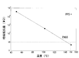
- FIG. 4 shows the surface resistivity of various resins.
- a nylon resin PA66 in FIG. 4
- the surface resistivity at 150 ° C. was less than 1.0 ⁇ 10 10 ⁇ .
- PPS in FIG. 4 polyphenylene sulfide having an insulation resistance of 10 M ⁇ or more
- the surface resistivity at 150 ° C. was 1.0 ⁇ 10 10 ⁇ or more. This shows that a knock sensor can be used at 150 ° C. or higher by using a resin molded body having a surface resistivity at 150 ° C. of 1.0 ⁇ 10 10 ⁇ or higher.
- the surface resistivity at 150 ° C. is 1.0 ⁇ 10 10 ⁇ or more, and it can be seen that it can be used in the present invention.
- This surface resistivity is obtained in accordance with JIS K6911. A sample in which a bulk body is formed from the material constituting the resin molded body 110 and a plurality of annular electrodes are provided on the surface of the bulk body. Prepared body and asked.
- the insulation resistance of the knocking sensor is the insulation resistance between the metal shell 12 and the upper electrode 16, the insulation resistance between the metal shell 12 and the lower electrode 14, and between the upper electrode 16 and the lower electrode 14. And the insulation resistance between the upper electrode 16 and the weight 17 were measured and adopted as the lowest resistance value.
- the present invention is not limited to the above-described embodiment, but extends to various modifications and equivalents included in the spirit and scope of the present invention.
- the weight 17 is held by the nut 19 which is a separate member via the disc spring 18.
- the disc spring 18 may be omitted, and the weight and the nut may be attached. You may comprise by the integrated one member.
- the nut 19 does not need to be fixed to the metal shell 12 by screwing, and may be fixed to the upper portion of the metal shell 12 by welding.
- the structure which integrated the connector part 11b in the resin molding 11 was employ
- the output of the piezoelectric element 15 may be taken out of the output.
- PET having a thickness of 0.35 mm, an inner diameter of 14.72 mm and an outer diameter of 23.10 mm is used as the upper insulating plate 13 t and the lower insulating plate 13, PZT (lead zirconate titanate) is used as the piezoelectric element 15, and iron is used as the weight 17.
- PZT lead zirconate titanate
- iron is used as the weight 17.
- Two knocking sensors 10 were produced using materials, using an iron material as the metal shell 12, and using a nylon resin and polyphenylene sulfide (PPS) as the resin molded body 11, respectively. The insulation resistance value of the obtained knocking sensor 10 at 150 ° C. was measured.
- the measurement is performed by measuring the insulation resistance between the metal shell 12 and the upper electrode 16, the insulation resistance between the metal shell 12 and the lower electrode 14, the insulation resistance between the upper electrode 16 and the lower electrode 14, and the upper electrode.
- the insulation resistance between 16 and the weight 17 was measured, and the lowest resistance value was adopted.
- the insulation resistance (insulation resistance value) was measured by applying a voltage of 500 V between the above members using an insulation resistance meter WT-8653 (manufactured by Hioki Electric Co., Ltd.).
- the insulation resistance value is less than 10 M ⁇ at 150 ° C.
- polyphenylene sulfide PPS in FIG. 3
- the insulation resistance value was 10 M ⁇ or more at 150 ° C.
- the insulation resistance value at 50 ° C. when nylon resin is used as the resin molding, and the insulation resistance value at 50 ° C. and 100 ° C. when polyphenylene sulfide is used as the resin molding are the upper limit of measurement of the insulation resistance meter. Since the values are shown, the upper limit value is shown in FIG. As described above, it was confirmed that the knocking sensor of the present invention using polyphenylene sulfide as the resin molding exhibits good insulating properties at high temperatures.
Landscapes
- Physics & Mathematics (AREA)
- General Physics & Mathematics (AREA)
- Chemical & Material Sciences (AREA)
- Engineering & Computer Science (AREA)
- Combustion & Propulsion (AREA)
- Measurement Of Mechanical Vibrations Or Ultrasonic Waves (AREA)
Abstract
Priority Applications (3)
| Application Number | Priority Date | Filing Date | Title |
|---|---|---|---|
| PCT/JP2011/001056 WO2012114380A1 (fr) | 2011-02-24 | 2011-02-24 | Capteur de cliquetis |
| US13/583,944 US9182309B2 (en) | 2011-02-24 | 2011-02-24 | Knocking sensor |
| CN201180065709.4A CN103328944B (zh) | 2011-02-24 | 2011-02-24 | 爆震传感器 |
Applications Claiming Priority (1)
| Application Number | Priority Date | Filing Date | Title |
|---|---|---|---|
| PCT/JP2011/001056 WO2012114380A1 (fr) | 2011-02-24 | 2011-02-24 | Capteur de cliquetis |
Publications (1)
| Publication Number | Publication Date |
|---|---|
| WO2012114380A1 true WO2012114380A1 (fr) | 2012-08-30 |
Family
ID=46720205
Family Applications (1)
| Application Number | Title | Priority Date | Filing Date |
|---|---|---|---|
| PCT/JP2011/001056 Ceased WO2012114380A1 (fr) | 2011-02-24 | 2011-02-24 | Capteur de cliquetis |
Country Status (3)
| Country | Link |
|---|---|
| US (1) | US9182309B2 (fr) |
| CN (1) | CN103328944B (fr) |
| WO (1) | WO2012114380A1 (fr) |
Families Citing this family (3)
| Publication number | Priority date | Publication date | Assignee | Title |
|---|---|---|---|---|
| FR3064071B1 (fr) * | 2017-03-20 | 2019-07-26 | Continental Automotive France | Capteur accelerometre avec au moins une rondelle isolante a ailettes |
| CN111896171A (zh) * | 2019-05-06 | 2020-11-06 | 纬湃汽车电子(长春)有限公司 | 爆震传感器 |
| CN112444341B (zh) * | 2019-08-30 | 2022-10-28 | 纬湃汽车电子(长春)有限公司 | 爆震传感器 |
Citations (5)
| Publication number | Priority date | Publication date | Assignee | Title |
|---|---|---|---|---|
| JPH01262336A (ja) * | 1988-04-13 | 1989-10-19 | Mitsubishi Electric Corp | 振動検出器 |
| JPH10267747A (ja) * | 1997-03-26 | 1998-10-09 | Unisia Jecs Corp | ノックセンサ |
| JP2003065998A (ja) * | 2001-08-24 | 2003-03-05 | Daikin Ind Ltd | ブッシュ、リード線ユニット及び自動車用酸素センサー |
| JP2005292123A (ja) * | 2004-03-12 | 2005-10-20 | Ngk Spark Plug Co Ltd | 非共振型ノッキングセンサ |
| JP2006010624A (ja) * | 2004-06-29 | 2006-01-12 | Denso Corp | 圧力検出装置 |
Family Cites Families (29)
| Publication number | Priority date | Publication date | Assignee | Title |
|---|---|---|---|---|
| JPH03143958A (ja) | 1989-10-31 | 1991-06-19 | Tosoh Corp | ポリフェニレンスルフィド樹脂組成物 |
| US5258442A (en) | 1989-10-31 | 1993-11-02 | Tosoh Corporation | Polyphenylene sulfide resin composition |
| JPH0512740A (ja) | 1991-07-01 | 1993-01-22 | Ricoh Co Ltd | 光磁気記録方式 |
| JPH11105097A (ja) | 1997-10-06 | 1999-04-20 | Kurabe Ind Co Ltd | チューブ及びそれを用いた自動車用コントロールケーブル |
| JP4062779B2 (ja) | 1998-07-01 | 2008-03-19 | 株式会社村田製作所 | 超音波センサ |
| JP3657166B2 (ja) | 2000-02-23 | 2005-06-08 | 日本特殊陶業株式会社 | 圧電ノックセンサ |
| JP3823292B2 (ja) | 2001-11-27 | 2006-09-20 | 日帝無線株式会社 | 常閉式小型振動センサ |
| JP4153213B2 (ja) | 2002-02-05 | 2008-09-24 | 日帝無線株式会社 | 常閉式小型振動センサ |
| US6752005B2 (en) | 2002-04-26 | 2004-06-22 | Ngk Spark Plug Co., Ltd. | Nonresonant type knock sensor |
| JP3692092B2 (ja) | 2002-04-26 | 2005-09-07 | 日本特殊陶業株式会社 | ノッキングセンサ |
| JP3660653B2 (ja) | 2002-08-23 | 2005-06-15 | 日本特殊陶業株式会社 | 非共振型ノッキングセンサ |
| JP2004117045A (ja) | 2002-09-24 | 2004-04-15 | Honda Elesys Co Ltd | シャント抵抗器 |
| JP3888314B2 (ja) | 2003-02-20 | 2007-02-28 | 株式会社デンソー | ノックセンサ |
| JP3996542B2 (ja) | 2003-05-08 | 2007-10-24 | アルプス電気株式会社 | 電極間の接続構造及び前記接続構造を用いたセンサ |
| JP4068580B2 (ja) | 2004-03-04 | 2008-03-26 | 日本特殊陶業株式会社 | 非共振型ノッキングセンサ |
| US7191658B2 (en) | 2004-06-11 | 2007-03-20 | Denso Corporation | Pressure-detecting device and method of manufacturing the same |
| JP2005351789A (ja) | 2004-06-11 | 2005-12-22 | Denso Corp | 圧力検出装置の製造方法 |
| JP2006151442A (ja) | 2004-11-29 | 2006-06-15 | Asahi Glass Co Ltd | 燃料用タンク又は燃料輸送用ホース用の含フッ素重合体成形体及び積層体 |
| WO2007004583A1 (fr) | 2005-07-01 | 2007-01-11 | Ngk Spark Plug Co., Ltd. | Capteur d’état de liquide |
| GB2436395A (en) | 2006-03-24 | 2007-09-26 | Tyco Electronics | A heat resistant cable |
| DE102006033638A1 (de) | 2006-07-20 | 2008-01-24 | Robert Bosch Gmbh | Druckmesseinrichtung |
| JP2008039571A (ja) | 2006-08-04 | 2008-02-21 | Denso Corp | 電流センサ |
| JP2008128917A (ja) | 2006-11-23 | 2008-06-05 | Ngk Spark Plug Co Ltd | 非共振型ノッキングセンサの取付け構造 |
| JP4691006B2 (ja) | 2006-12-11 | 2011-06-01 | 日本特殊陶業株式会社 | ノッキングセンサ |
| JP2008163222A (ja) | 2006-12-28 | 2008-07-17 | Toray Ind Inc | ポリフェニレンサルファイド樹脂組成物 |
| US8040024B2 (en) * | 2008-03-05 | 2011-10-18 | Ngk Spark Plug Co., Ltd. | Piezoceramic material, piezoelectric element and non-resonance knock sensor |
| JP4962361B2 (ja) | 2008-03-12 | 2012-06-27 | 東レ株式会社 | ポリフェニレンサルファイド繊維の製造方法およびポリフェニレンサルファイド繊維 |
| JP2009263640A (ja) | 2008-04-04 | 2009-11-12 | Sumitomo Chemical Co Ltd | 熱伝導性樹脂組成物及びその用途 |
| JP5647120B2 (ja) * | 2010-01-29 | 2014-12-24 | 日本特殊陶業株式会社 | 無鉛圧電磁器組成物、それを用いた圧電素子、ノックセンサ、及び、無鉛圧電磁器組成物の製造方法 |
-
2011
- 2011-02-24 WO PCT/JP2011/001056 patent/WO2012114380A1/fr not_active Ceased
- 2011-02-24 CN CN201180065709.4A patent/CN103328944B/zh active Active
- 2011-02-24 US US13/583,944 patent/US9182309B2/en active Active
Patent Citations (5)
| Publication number | Priority date | Publication date | Assignee | Title |
|---|---|---|---|---|
| JPH01262336A (ja) * | 1988-04-13 | 1989-10-19 | Mitsubishi Electric Corp | 振動検出器 |
| JPH10267747A (ja) * | 1997-03-26 | 1998-10-09 | Unisia Jecs Corp | ノックセンサ |
| JP2003065998A (ja) * | 2001-08-24 | 2003-03-05 | Daikin Ind Ltd | ブッシュ、リード線ユニット及び自動車用酸素センサー |
| JP2005292123A (ja) * | 2004-03-12 | 2005-10-20 | Ngk Spark Plug Co Ltd | 非共振型ノッキングセンサ |
| JP2006010624A (ja) * | 2004-06-29 | 2006-01-12 | Denso Corp | 圧力検出装置 |
Also Published As
| Publication number | Publication date |
|---|---|
| US9182309B2 (en) | 2015-11-10 |
| US20130000387A1 (en) | 2013-01-03 |
| CN103328944B (zh) | 2016-04-13 |
| CN103328944A (zh) | 2013-09-25 |
Similar Documents
| Publication | Publication Date | Title |
|---|---|---|
| US9182309B2 (en) | Knocking sensor | |
| JP5731747B2 (ja) | ノッキングセンサ | |
| JP5778476B2 (ja) | ノッキングセンサ | |
| US9709454B2 (en) | Non-resonant knock sensor | |
| CN105339768B (zh) | 爆震传感器 | |
| JP5670378B2 (ja) | 非共振型ノッキングセンサおよび非共振型ノッキングセンサの製造方法 | |
| KR20070098470A (ko) | 노크 센서 | |
| CN1755340A (zh) | 爆震传感器 | |
| JP6602740B2 (ja) | 圧力センサ | |
| JP4068580B2 (ja) | 非共振型ノッキングセンサ | |
| JP2008185414A (ja) | ノックセンサ | |
| JP6113366B2 (ja) | 圧力測定グロープラグ用のセンサモジュール | |
| WO2012137395A1 (fr) | Capuchon de bougie | |
| US9957873B2 (en) | Sensor | |
| JP4242850B2 (ja) | 非共振型ノッキングセンサ | |
| JP5129070B2 (ja) | ノッキングセンサ | |
| JP2006112858A (ja) | 圧電式加速度センサ | |
| CN111896171A (zh) | 爆震传感器 | |
| JP2017223475A (ja) | 非共振型ノッキングセンサ | |
| JPS6230790Y2 (fr) | ||
| JP2013007612A (ja) | 非共振型ノッキングセンサ | |
| JP2014119411A (ja) | 非共振型ノッキングセンサ | |
| JP2016151478A (ja) | センサ |
Legal Events
| Date | Code | Title | Description |
|---|---|---|---|
| WWE | Wipo information: entry into national phase |
Ref document number: 13583944 Country of ref document: US |
|
| 121 | Ep: the epo has been informed by wipo that ep was designated in this application |
Ref document number: 11859286 Country of ref document: EP Kind code of ref document: A1 |
|
| WWE | Wipo information: entry into national phase |
Ref document number: 1301004029 Country of ref document: TH |
|
| NENP | Non-entry into the national phase |
Ref country code: DE |
|
| 122 | Ep: pct application non-entry in european phase |
Ref document number: 11859286 Country of ref document: EP Kind code of ref document: A1 |
|
| NENP | Non-entry into the national phase |
Ref country code: JP |