WO2012114412A1 - Dispositif sans fil - Google Patents
Dispositif sans fil Download PDFInfo
- Publication number
- WO2012114412A1 WO2012114412A1 PCT/JP2011/007083 JP2011007083W WO2012114412A1 WO 2012114412 A1 WO2012114412 A1 WO 2012114412A1 JP 2011007083 W JP2011007083 W JP 2011007083W WO 2012114412 A1 WO2012114412 A1 WO 2012114412A1
- Authority
- WO
- WIPO (PCT)
- Prior art keywords
- unit
- vehicle
- notification
- terminal device
- received power
- Prior art date
- Legal status (The legal status is an assumption and is not a legal conclusion. Google has not performed a legal analysis and makes no representation as to the accuracy of the status listed.)
- Ceased
Links
Images






Classifications
-
- G—PHYSICS
- G08—SIGNALLING
- G08G—TRAFFIC CONTROL SYSTEMS
- G08G1/00—Traffic control systems for road vehicles
- G08G1/09—Arrangements for giving variable traffic instructions
- G08G1/0962—Arrangements for giving variable traffic instructions having an indicator mounted inside the vehicle, e.g. giving voice messages
- G08G1/0967—Systems involving transmission of highway information, e.g. weather, speed limits
- G08G1/096766—Systems involving transmission of highway information, e.g. weather, speed limits where the system is characterised by the origin of the information transmission
- G08G1/096791—Systems involving transmission of highway information, e.g. weather, speed limits where the system is characterised by the origin of the information transmission where the origin of the information is another vehicle
-
- G—PHYSICS
- G08—SIGNALLING
- G08G—TRAFFIC CONTROL SYSTEMS
- G08G1/00—Traffic control systems for road vehicles
- G08G1/16—Anti-collision systems
- G08G1/161—Decentralised systems, e.g. inter-vehicle communication
-
- G—PHYSICS
- G08—SIGNALLING
- G08G—TRAFFIC CONTROL SYSTEMS
- G08G1/00—Traffic control systems for road vehicles
- G08G1/09—Arrangements for giving variable traffic instructions
- G08G1/0962—Arrangements for giving variable traffic instructions having an indicator mounted inside the vehicle, e.g. giving voice messages
- G08G1/0967—Systems involving transmission of highway information, e.g. weather, speed limits
- G08G1/096708—Systems involving transmission of highway information, e.g. weather, speed limits where the received information might be used to generate an automatic action on the vehicle control
- G08G1/096716—Systems involving transmission of highway information, e.g. weather, speed limits where the received information might be used to generate an automatic action on the vehicle control where the received information does not generate an automatic action on the vehicle control
-
- G—PHYSICS
- G08—SIGNALLING
- G08G—TRAFFIC CONTROL SYSTEMS
- G08G1/00—Traffic control systems for road vehicles
- G08G1/09—Arrangements for giving variable traffic instructions
- G08G1/0962—Arrangements for giving variable traffic instructions having an indicator mounted inside the vehicle, e.g. giving voice messages
- G08G1/0967—Systems involving transmission of highway information, e.g. weather, speed limits
- G08G1/096766—Systems involving transmission of highway information, e.g. weather, speed limits where the system is characterised by the origin of the information transmission
- G08G1/096783—Systems involving transmission of highway information, e.g. weather, speed limits where the system is characterised by the origin of the information transmission where the origin of the information is a roadside individual element
-
- H—ELECTRICITY
- H04—ELECTRIC COMMUNICATION TECHNIQUE
- H04B—TRANSMISSION
- H04B17/00—Monitoring; Testing
- H04B17/30—Monitoring; Testing of propagation channels
- H04B17/309—Measuring or estimating channel quality parameters
- H04B17/318—Received signal strength
-
- H—ELECTRICITY
- H04—ELECTRIC COMMUNICATION TECHNIQUE
- H04B—TRANSMISSION
- H04B17/00—Monitoring; Testing
- H04B17/20—Monitoring; Testing of receivers
- H04B17/24—Monitoring; Testing of receivers with feedback of measurements to the transmitter
-
- H—ELECTRICITY
- H04—ELECTRIC COMMUNICATION TECHNIQUE
- H04B—TRANSMISSION
- H04B17/00—Monitoring; Testing
- H04B17/20—Monitoring; Testing of receivers
- H04B17/26—Monitoring; Testing of receivers using historical data, averaging values or statistics
Definitions
- the present invention relates to communication technology, and more particularly to a wireless device that receives a signal including predetermined information.
- Road-to-vehicle communication is being studied to prevent collisions at intersections.
- information on the situation of the intersection is communicated between the roadside device and the vehicle-mounted device.
- Road-to-vehicle communication requires the installation of roadside equipment, which increases labor and cost.
- installation of a roadside machine will become unnecessary.
- the current position information is detected in real time by GPS (Global Positioning System), etc., and the position information is exchanged between the vehicle-mounted devices so that the own vehicle and the other vehicle each enter the intersection. (See, for example, Patent Document 1).
- a signal transmitted from the mobile body is received by the mobile terminal.
- the mobile terminal detects the presence from the moving body from the received signal, or estimates the distance from the received intensity to the moving body (see, for example, Patent Document 2).
- CSMA / CA Carrier Sense Multiple Access Avoidance
- ITS Intelligent Transport Systems
- the terminal device is carried by a pedestrian in addition to being mounted on the vehicle.
- the terminal device carried by the pedestrian notifies the in-vehicle terminal device of the existing position.
- the frequency of warnings at the terminal devices mounted on the vehicle increases and the alerting effect decreases.
- a terminal device mounted on the vehicle outputs a warning only when the received power is large. This is based on the idea that nearby pedestrians are more dangerous. However, even when the received power is small, the risk may be high. For example, this is a case where a pedestrian who is out of line of sight enters the line of sight. In such situations, early warning is desired.
- the present invention has been made in view of such circumstances, and an object of the present invention is to provide a technique for notifying the existence of a terminal device with high risk.
- a wireless device includes a receiving unit that receives a packet signal from another wireless device, a processing unit that processes the packet signal received by the receiving unit, and a receiving unit.
- a measurement unit that measures received power for a received packet signal, a monitoring unit that monitors fluctuations in received power measured by the measurement unit, and received power so that fluctuations monitored by the monitoring unit are larger than a threshold value.
- a notification unit that starts notification according to the content of the packet signal processed by the processing unit.
- the presence of a terminal device with high risk can be notified.
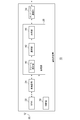
- FIGS. 3A to 3D are diagrams showing frame formats defined in the communication system of FIG.
- FIGS. 4 (a)-(b) are diagrams showing the configuration of the subframes of FIGS. 3 (a)-(d).
- FIGS. 5A and 5B are diagrams showing a format of a MAC frame stored in a packet signal defined in the communication system of FIG.
- It is a flowchart which shows the notification procedure by the terminal device of FIG.
- FIG. is a figure which shows the structure of the terminal device which concerns on the modification of this invention.
- Embodiments of the present invention relate to a communication system that performs vehicle-to-vehicle communication between terminal devices mounted on a vehicle, and also executes road-to-vehicle communication from a base station device installed at an intersection or the like to a terminal device.
- the terminal device broadcasts and transmits a packet signal storing information such as the speed and position of the vehicle (hereinafter referred to as “data”).
- the other terminal device receives the packet signal and recognizes the approach of the vehicle based on the data. The driver is alerted by notifying the driver of the approach of the vehicle.
- the base station apparatus In order to reduce interference between vehicle-to-vehicle communication and road-to-vehicle communication, the base station apparatus repeatedly defines a frame including a plurality of subframes.
- the base station apparatus selects any of a plurality of subframes for road-to-vehicle communication, and broadcasts a packet signal in which control information and the like are stored during the period of the head portion of the selected subframe.
- the control information includes information related to a period for the base station apparatus to broadcast the packet signal (hereinafter referred to as “road vehicle transmission period”).
- the terminal device specifies a road and vehicle transmission period based on the control information, and transmits a packet signal in a period other than the road and vehicle transmission period.
- the inter-vehicle communication is performed by the CSMA method in a period for performing inter-vehicle communication other than the road-vehicle transmission period (hereinafter referred to as “vehicle transmission period”).
- vehicle transmission period Such a terminal device is also carried by a pedestrian.
- a terminal device carried by a pedestrian is battery-driven and requires low power consumption. Therefore, the terminal device carried by the pedestrian only broadcasts a packet signal storing data, and does not notify the pedestrian of the approach of the vehicle. As the number of pedestrians increases, warnings continue to be output, so the alerting power is reduced.
- the terminal device mounted on the vehicle warns the presence of a terminal device having a reception power equal to or higher than a threshold value among terminal devices carried by pedestrians. Under such circumstances, a pedestrian who is out of sight may enter the sight. At that time, an early warning is desired even if the received power is smaller than the threshold value. Therefore, the following processing is executed when the terminal device according to the present embodiment, particularly mounted in a vehicle. In the following, even terminal devices carried by pedestrians are referred to as inter-vehicle communication and road-to-vehicle communication.
- the terminal device receives the packet signal.
- the terminal device measures the received power of the packet signal and monitors the fluctuation of the received power.
- the terminal device outputs a warning when the reception power increases so that the fluctuation becomes larger than the threshold value.
- FIG. 1 shows a configuration of a communication system 100 according to an embodiment of the present invention. This corresponds to a case where one intersection is viewed from above.
- the communication system 100 includes a base station device 10, a first vehicle 12a, a second vehicle 12b, a third vehicle 12c, a fourth vehicle 12d, a fifth vehicle 12e, a sixth vehicle 12f, and a seventh vehicle 12g, collectively referred to as a vehicle 12. , The eighth vehicle 12h, and the network 202.
- Each vehicle 12 is equipped with a terminal device (not shown).
- the area 212 is formed around the base station apparatus 10, and the outside area 214 is formed outside the area 212.
- the road that goes in the horizontal direction of the drawing that is, the left and right direction
- intersects the vertical direction of the drawing that is, the road that goes in the up and down direction, at the central portion.
- the upper side of the drawing corresponds to the direction “north”
- the left side corresponds to the direction “west”
- the lower side corresponds to the direction “south”
- the right side corresponds to the direction “east”.
- the intersection of the two roads is an “intersection”.
- the first vehicle 12a and the second vehicle 12b are traveling from left to right
- the third vehicle 12c and the fourth vehicle 12d are traveling from right to left
- the fifth vehicle 12e and the sixth vehicle 12f are traveling from the top to the bottom
- the seventh vehicle 12g and the eighth vehicle 12h are traveling from the bottom to the top.
- the communication system 100 arranges the base station apparatus 10 at the intersection.
- the base station device 10 controls communication between terminal devices.
- the base station device 10 repeatedly generates a frame including a plurality of subframes based on a signal received from a GPS satellite (not shown) and a frame formed by another base station device 10 (not shown).
- the road vehicle transmission period can be set at the head of each subframe.
- the base station apparatus 10 selects a subframe in which the road and vehicle transmission period is not set by another base station apparatus 10 from among the plurality of subframes.
- the base station apparatus 10 sets a road and vehicle transmission period at the beginning of the selected subframe.
- the base station apparatus 10 notifies the packet signal in the set road and vehicle transmission period.
- a plurality of types of data are assumed as data to be included in the packet signal.
- One is control information and the other is traffic jam information.
- the base station apparatus 10 receives the traffic jam information from the outside, which will be described later.
- the vehicle 12 is driven by an engine and is equipped with a terminal device (not shown).
- the terminal device generates a frame based on the control information included in the received packet signal.
- the frame generated in each of the plurality of terminal devices is synchronized with the frame generated in the base station device 10.
- reports a packet signal by performing CSMA / CA in a vehicle transmission period.
- the terminal device stores information on the location in the packet signal.
- the terminal device also stores control information in the packet signal. That is, the control information transmitted from the base station device 10 is transferred by the terminal device.
- a terminal device that cannot receive a packet signal from the base station device 10 that is, a terminal device existing outside the area 214 broadcasts the packet signal by executing CSMA / CA regardless of the frame configuration. Furthermore, the terminal device notifies the driver of the approach of the vehicle on which the other terminal device is mounted by receiving a packet signal from the other terminal device.
- the terminal device is also carried by a pedestrian (not shown).
- a pedestrian does not have a function for notifying the contents of the received packet signal as compared with the terminal device mounted on the vehicle 12. Therefore, the terminal device carried by the pedestrian stores information on the presence position in the packet signal and notifies the user.
- the packet signal notified from the terminal device carried by the pedestrian is received by the terminal device mounted on the vehicle 12.
- the terminal device mounted on the vehicle 12 measures the received power of the packet signal. If the received power is equal to or higher than a predetermined threshold (hereinafter referred to as “first threshold”), the terminal device mounted on the vehicle 12 warns the presence of a pedestrian. Further, the terminal device mounted on the vehicle 12 monitors the fluctuation of the received power of the packet signal.
- first threshold a predetermined threshold
- the terminal device mounted on the vehicle 12 warns the presence of a pedestrian.
- the former warning is made to call attention to a pedestrian existing in the vicinity of the vehicle 12, and the latter warning is made to call attention to a pedestrian who tries to enter the line of sight from outside the line of sight of the vehicle 12. To be made.
- FIG. 2 shows the configuration of the base station apparatus 10.
- the base station apparatus 10 includes an antenna 20, an RF unit 22, a modem unit 24, a processing unit 26, a control unit 30, and a network communication unit 34.
- the processing unit 26 includes a frame definition unit 40, a selection unit 42, and a generation unit 46.
- the RF unit 22 receives a packet signal from a terminal device (not shown) or another base station device 10 by the antenna 20 as a reception process.
- the RF unit 22 performs frequency conversion on the received radio frequency packet signal to generate a baseband packet signal. Further, the RF unit 22 outputs a baseband packet signal to the modem unit 24.
- baseband packet signals are formed by in-phase and quadrature components, so two signal lines should be shown, but here only one signal line is shown for clarity. Shall be shown.
- the RF unit 22 also includes an LNA (Low Noise Amplifier), a mixer, an AGC, and an A / D conversion unit.
- LNA Low Noise Amplifier
- the RF unit 22 performs frequency conversion on the baseband packet signal input from the modem unit 24 as a transmission process, and generates a radio frequency packet signal. Further, the RF unit 22 transmits a radio frequency packet signal from the antenna 20 during the road-vehicle transmission period.
- the RF unit 22 also includes a PA (Power Amplifier), a mixer, and a D / A conversion unit.
- PA Power Amplifier
- the modem unit 24 demodulates the baseband packet signal from the RF unit 22 as a reception process. Further, the modem unit 24 outputs the demodulated result to the processing unit 26. The modem unit 24 also modulates the data from the processing unit 26 as a transmission process. Further, the modem unit 24 outputs the modulated result to the RF unit 22 as a baseband packet signal.
- the modem unit 24 since the communication system 100 corresponds to the OFDM (Orthogonal Frequency Division Multiplexing) modulation method, the modem unit 24 also executes FFT (Fast Fourier Transform) as reception processing and IFFT (Inverse TransFastFast) as transmission processing. Also execute.
- the frame defining unit 40 receives a signal from a GPS satellite (not shown), and acquires time information based on the received signal.
- the frame defining unit 40 generates a plurality of frames based on the time information. For example, the frame defining unit 40 generates 10 frames of “100 msec” by dividing the period of “1 sec” into 10 on the basis of the timing indicated by the time information. By repeating such processing, the frame is defined to be repeated.
- the frame defining unit 40 may detect the control information from the demodulation result and generate a frame based on the detected control information.
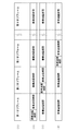
- FIGS. 3A to 3D show frame formats defined in the communication system 100.
- FIG. FIG. 3A shows the structure of the frame.
- the frame is formed of N subframes indicated as the first subframe to the Nth subframe. For example, when the frame length is 100 msec and N is 8, a subframe having a length of 12.5 msec is defined.
- the description of FIGS. 3B to 3D will be described later, and returns to FIG.
- the selection unit 42 selects a subframe in which a road and vehicle transmission period is to be set from among a plurality of subframes included in the frame. More specifically, the selection unit 42 receives a frame defined by the frame defining unit 40. The selection unit 42 inputs a demodulation result from another base station device 10 or a terminal device (not shown) via the RF unit 22 and the modem unit 24. The selection unit 42 extracts a demodulation result from another base station apparatus 10 from the input demodulation results. The selection unit 42 identifies the subframe that has not received the demodulation result by specifying the subframe that has received the demodulation result.
- the selection unit 42 selects one subframe at random.
- the selection unit 42 acquires reception power corresponding to the demodulation result, and gives priority to subframes with low reception power.
- FIG. 3B shows a configuration of a frame generated by the first base station apparatus 10a.
- the first base station apparatus 10a sets a road and vehicle transmission period at the beginning of the first subframe.
- the 1st base station apparatus 10a sets a vehicle transmission period following the road and vehicle transmission period in a 1st sub-frame.
- the vehicle transmission period is a period during which the terminal device can notify the packet signal. That is, in the road and vehicle transmission period which is the head period of the first subframe, the first base station apparatus 10a can notify the packet signal, and in the frame, the terminal apparatus transmits in the vehicle and vehicle transmission period other than the road and vehicle transmission period. It is defined that the packet signal can be broadcast.
- the first base station apparatus 10a sets only the vehicle transmission period from the second subframe to the Nth subframe.
- FIG. 3C shows a configuration of a frame generated by the second base station apparatus 10b.
- the second base station apparatus 10b sets a road and vehicle transmission period at the beginning of the second subframe.
- the second base station apparatus 10b sets the vehicle transmission period from the first stage of the road and vehicle transmission period in the second subframe, from the first subframe and the third subframe to the Nth subframe.
- FIG. 3D shows a configuration of a frame generated by the third base station apparatus 10c.
- the third base station apparatus 10c sets a road and vehicle transmission period at the beginning of the third subframe.
- the third base station apparatus 10c sets the vehicle transmission period from the first stage of the road and vehicle transmission period in the third subframe, the first subframe, the second subframe, and the fourth subframe to the Nth subframe.
- the plurality of base station apparatuses 10 select different subframes, and set the road and vehicle transmission period at the head portion of the selected subframe.
- the selection unit 42 outputs the selected subframe number to the generation unit 46.
- the generation unit 46 sets a road and vehicle transmission period in the subframe of the subframe number received from the selection unit 42, and generates an RSU packet signal to be notified during the road and vehicle transmission period.
- the RSU packet signal and the packet signal are used without distinction.
- FIGS. 4A to 4B show subframe configurations.
- FIG. 4A shows a subframe in which a road and vehicle transmission period is set. As illustrated, one subframe is configured in the order of a road and vehicle transmission period and a vehicle and vehicle transmission period.
- FIG. 4B shows the arrangement of packet signals during the road and vehicle transmission period.
- a plurality of RSU packet signals are arranged in the road and vehicle transmission period.
- the front and rear packet signals are separated by SIFS (Short Interframe Space).
- FIG. 5A and 5B show the format of a MAC frame stored in a packet signal defined in the communication system 100.
- FIG. FIG. 5A shows the format of the MAC frame.
- “MAC header”, “LLC header”, “message header”, “data payload”, and “FCS” are arranged in order from the top. Information included in the data payload will be described later.
- FIG. 5B is a diagram illustrating a configuration of a message header generated by the generation unit 46.
- the message header includes a basic part.
- the basic part includes “protocol version”, “transmission node type”, “number of reuses”, “TSF timer”, and “RSU transmission period length”.
- the protocol version indicates the version of the corresponding protocol.
- the transmission node type indicates the transmission source of the packet signal including the MAC frame. For example, “0” indicates a terminal device, and “1” indicates the base station device 10.
- the selection unit 42 uses the value of the transmission node type.
- the reuse count indicates an index of validity when the message header is transferred by the terminal device, and the TSF timer indicates the transmission time.
- the RSU transmission period length indicates the length of the road and vehicle transmission period, and can be said to be information relating to the road and vehicle transmission period.
- the network communication unit 34 is connected to a network 202 (not shown).
- the network communication unit 34 receives traffic jam information from the network 202.
- the generation unit 46 acquires the traffic jam information from the network communication unit 34 and stores it in the data payload, thereby generating the RSU packet signal described above.
- the control unit 30 controls processing of the entire base station apparatus 10.
- This configuration can be realized in terms of hardware by a CPU, memory, or other LSI of any computer, and in terms of software, it can be realized by a program loaded in the memory, but here it is realized by their cooperation.
- Draw functional blocks Accordingly, those skilled in the art will understand that these functional blocks can be realized in various forms only by hardware, or by a combination of hardware and software.
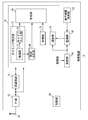
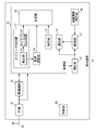
- FIG. 6 shows the configuration of the terminal device 14 mounted on the vehicle 12.
- the terminal device 14 includes an antenna 50, an RF unit 52, a modem unit 54, a processing unit 56, a control unit 58, a measurement unit 80, and a monitoring unit 82.
- the processing unit 56 includes a generation unit 64, a timing identification unit 60, a transfer determination unit 68, a notification unit 70, and an acquisition unit 72.
- the timing specifying unit 60 includes an extraction unit 66 and a carrier sense unit 62.
- the antenna 50, the RF unit 52, and the modem unit 54 execute the same processing as the antenna 20, the RF unit 22, and the modem unit 24 in FIG. Therefore, here, the difference will be mainly described.
- the modem unit 54 and the processing unit 56 receive packet signals from other terminal devices 14 and the base station device 10 (not shown). As described above, the modem unit 54 and the processing unit 56 receive the packet signal from the base station apparatus 10 during the road and vehicle transmission period. As described above, the modem unit 54 and the processing unit 56 receive packet signals from other terminal devices 14 during the vehicle transmission period.
- the extraction unit 66 specifies the timing of the subframe in which the road-vehicle transmission period is arranged. At that time, the extraction unit 66 estimates that it exists in the area 212 of FIG. The extraction unit 66 generates a frame based on the timing of the subframe and the content of the message header of the packet signal, specifically, the content of the RSU transmission period length. Note that the generation of the frame only needs to be performed in the same manner as the frame defining unit 40 described above, and thus the description thereof is omitted here. As a result, the extraction unit 66 generates a frame synchronized with the frame formed in the base station apparatus 10.
- the extraction unit 66 estimates that the extraction unit 66 exists outside the area 214 in FIG. When it is estimated that the extraction unit 66 exists in the area 212, the extraction unit 66 selects the vehicle transmission period. When it is estimated that the extraction unit 66 exists outside the area 214, the extraction unit 66 selects a timing unrelated to the frame configuration. When the vehicle transmission period is selected, the extraction unit 66 outputs information on the frame and subframe timing and the vehicle transmission period to the carrier sense unit 62. When selecting the timing irrelevant to the frame configuration, the extraction unit 66 instructs the carrier sense unit 62 to execute carrier sense.
- the carrier sense unit 62 receives information on the timing of frames and subframes and the vehicle transmission period from the extraction unit 66.
- the carrier sense unit 62 measures the interference power by performing carrier sense during the vehicle transmission period.
- the carrier sense part 62 determines the transmission timing in a vehicle transmission period based on interference power. More specifically, the carrier sense unit 62 stores a predetermined threshold value in advance, and compares the interference power with the threshold value. If the interference power is smaller than the threshold value, the carrier sense unit 62 determines the transmission timing.
- the carrier sense unit 62 determines the transmission timing by executing CSMA without considering the frame configuration.
- the carrier sense unit 62 notifies the generation unit 64 of the determined transmission timing.
- the acquisition unit 72 includes a GPS receiver, a gyro sensor, a vehicle speed sensor, and the like (not shown). Based on data supplied from these, the location of the vehicle 12 (not shown), that is, the position of the vehicle 12 on which the terminal device 14 is mounted, the progress The direction, the moving speed, etc. (hereinafter collectively referred to as “position information”) are acquired. The existence position is indicated by latitude and longitude. Since a known technique may be used for these acquisitions, description thereof is omitted here. The acquisition unit 72 outputs the position information to the generation unit 64.
- the transfer determination unit 68 controls the transfer of the message header.
- the transfer determining unit 68 extracts a message header from the packet signal.
- the reuse count is set to “0”.
- the transfer determination unit 68 selects a message header to be transferred from the extracted message header.
- the transfer determination unit 68 may generate a new message header by combining the contents included in the plurality of message headers.
- the transfer determination unit 68 outputs the message header to be selected to the generation unit 64. At that time, the transfer determining unit 68 increases the number of reuses by “1”.
- the generation unit 64 receives position information from the acquisition unit 72 and receives a message header from the transfer determination unit 68.
- the generation unit 64 stores the position information in the data payload using the MAC frame shown in FIGS.
- the generation unit 64 generates a packet signal including a MAC frame, and broadcasts the generated packet signal via the modem unit 54, the RF unit 52, and the antenna 50 at the transmission timing determined by the carrier sense unit 62. Send.
- the transmission timing is included in the vehicle transmission period.
- the measuring unit 80 measures the received power for the packet signal received by the RF unit 52 and the modem unit 54. Since a known technique may be used for the measurement of the received power, the description thereof is omitted here. For example, the measurement of the received power is performed in units of OFDM symbols.
- the measurement results are sequentially output to the monitoring unit 82 and the notification unit 70.
- the monitoring unit 82 receives the measurement result of the received power from the measurement unit 80.
- the monitoring unit 82 monitors fluctuations in the measured received power. Specifically, the monitoring unit 82 sequentially calculates the difference in received power at adjacent measurement timings. At that time, filtering may be performed in order to smooth the fluctuation of the received power.
- the monitoring unit 82 outputs the calculated difference to the notification unit 70.
- the notification unit 70 acquires a packet signal from the base station apparatus 10 (not shown) in the road and vehicle transmission period, and acquires a packet signal from another terminal apparatus 14 (not shown) in the vehicle and vehicle transmission period.
- the packet signal includes information related to a transmission source device.
- the base station device 10, the terminal device 14 mounted on the vehicle 12, or the terminal device 14 carried by a pedestrian is indicated by the information regarding the device that is the transmission source.
- the notification unit 70 approaches the other vehicle 12 (not shown) according to the content of the data stored in the packet signal. To the driver via a monitor or speaker.
- the notification unit 70 receives the measurement result of the received power from the measurement unit 80 and also receives the difference from the monitoring unit 82. If the transmission source of the acquired packet signal is the terminal device 14 carried by the pedestrian, the notification unit 70 stores the packet signal if the received power measurement result is equal to or greater than the first threshold value. In accordance with the contents of the data, the driver is notified of the approach of a pedestrian (not shown) by display on the monitor. If the measurement result of the received power is smaller than the first threshold value, the notification unit 70 stores in the packet signal when the received power increases so that the difference from the monitoring unit 82 becomes larger than the second threshold value. Notification according to the contents of the received data is started. This notification is also made by display on the screen. For example, an icon is displayed on a part of the navigation screen, or a map near the intersection is enlarged. The control unit 58 controls the operation of the entire terminal device 14.
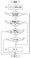
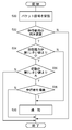
- FIG. 7 is a flowchart illustrating a notification procedure performed by the terminal device 14.
- the RF unit 52 and the modem unit 54 receive the packet signal (S10). If the terminal device 14 is for a pedestrian (Y at S12), the received power is smaller than the first threshold (Y at S14), and the fluctuation is larger than the second threshold (Y at S16), the notification unit 70 Performs notification (S18). If the received power is not smaller than the first threshold value (N in S14), the notification unit 70 performs notification (S18). If it is not the terminal device 14 for pedestrians (N in S12) or if the fluctuation is not larger than the second threshold value (N in S16), the process is terminated.
- This modification also relates to a communication system that performs vehicle-to-vehicle communication and road-to-vehicle communication.
- the present modification aims to provide an early warning and improve the alerting ability even if the received power is smaller than the threshold value.
- the terminal device according to the present modification outputs a warning when the received power increases so that the fluctuation of the received power becomes larger than the threshold value even if the received power is small.
- the terminal device limits the warning output when the risk is high. Therefore, the terminal device according to this modification outputs a warning only when the lighting device mounted on the vehicle is lit. This is because it is easy to overlook pedestrians.
- FIG. 8 shows the configuration of the terminal device 14 according to a modification of the present invention.
- the terminal device 14 has a lighting information acquisition unit 84 added to the terminal device 14 of FIG.
- the vehicle 12 (not shown) is provided with a lighting device, for example, a headlight.
- the lighting information acquisition unit 84 is connected to the lighting device and acquires information regarding the lighting state of the lighting device.
- the information regarding the lighting state of the lighting device indicates whether the lighting device is turned on or off.
- the lighting information acquisition part 84 may acquire the information regarding the lighting state of an illuminating device by the input from a driver
- the monitoring unit 82 receives information on the lighting state of the lighting device from the lighting information acquisition unit 84.
- the monitoring unit 82 outputs information regarding the lighting state of the lighting device to the notification unit 70 together with the calculated difference.
- the transmission source of the acquired packet signal is the terminal device 14 carried by the pedestrian and the measurement result of the received power is smaller than the first threshold value
- the notification unit 70 has a difference from the monitoring unit 82. If the received power increases so as to be larger than the second threshold and the information acquired in the lighting information acquisition unit 84 indicates a lighting state, notification is started.
- FIG. 9 is a flowchart illustrating a notification procedure performed by the terminal device 14.
- the RF unit 52 and the modem unit 54 receive the packet signal (S20). It is a terminal device 14 for pedestrians (Y in S22), the received power is smaller than the first threshold value (Y in S24), the fluctuation is larger than the second threshold value (Y in S26), and it is in the lighting state. If this is the case (Y in S28), the notification unit 70 performs notification (S30). If the received power is not smaller than the first threshold value (N in S24), the notification unit 70 performs notification (S30). If it is not the terminal device 14 for pedestrians (N in S22), or the fluctuation is not larger than the second threshold value (N in S26) or is not in the lighting state (N in S28), the process is terminated.
- Another modified example also relates to a communication system that executes vehicle-to-vehicle communication and road-to-vehicle communication.
- Another modification aims to warn early and suppress unnecessary warning even if the received power is smaller than the threshold value.
- the terminal device according to another modification outputs a warning when the received power increases so that the fluctuation of the received power becomes larger than the threshold even if the received power is small.
- the terminal device does not output a warning if the vehicle is stopped in order to suppress a useless warning. This is because there is no risk of collision with a pedestrian.
- FIG. 10 shows a configuration of a terminal device 14 according to another modification of the present invention.
- the terminal device 14 has a travel information acquisition unit 86 added to the terminal device 14 of FIG.
- the vehicle 12 (not shown) is provided with a speed sensor.
- the traveling information acquisition unit 86 is mounted on the vehicle 12 and acquires information related to the traveling state of the vehicle 12.
- the information regarding the traveling state indicates the traveling speed of the vehicle 12.
- the monitoring unit 82 receives information related to the traveling state from the traveling information acquisition unit 86.
- the monitoring unit 82 outputs information related to the traveling state to the notification unit 70 together with the calculated difference.
- the notification unit 70 When the transmission source of the acquired packet signal is the terminal device 14 carried by the pedestrian and the measurement result of the received power is smaller than the first threshold value, the notification unit 70 has a difference from the monitoring unit 82. If the received power increases so as to be larger than the second threshold value and the information acquired by the travel information acquisition unit 86 does not indicate a stop, notification is started. In addition, if the information acquired in the travel information acquisition unit 86 indicates stop, the notification unit 70 does not start notification.
- FIG. 11 is a flowchart illustrating a notification procedure performed by the terminal device 14.
- the RF unit 52 and the modem unit 54 receive the packet signal (S40).
- the terminal device 14 for pedestrians is not being stopped (N in S41) (Y in S42), the received power is smaller than the first threshold (Y in S44), and the fluctuation is larger than the second threshold. If this is the case (Y in S46), the notification unit 70 performs notification (S50). If the received power is not smaller than the first threshold value (N in S44), the notification unit 70 performs notification (S50). If it is in the stop state (Y in S41), not the pedestrian terminal device 14 (N in S42), or if the fluctuation is not greater than the second threshold (N in S46), the process is terminated.
- Still another modified example relates to a communication system that performs vehicle-to-vehicle communication and road-to-vehicle communication.
- Yet another modification is intended to provide an early warning even when the received power is smaller than a threshold value and to improve the alerting ability.
- the terminal device according to another modification outputs a warning when the received power increases so that the fluctuation of the received power becomes larger than the threshold even if the received power is small. .
- the terminal device limits the warning output when the risk is high. Therefore, the terminal device according to the present modification outputs a warning only when the width of the running road is narrow. This is because the danger of the pedestrian who has jumped out is higher.
- FIG. 12 shows a configuration of a terminal device 14 according to still another modification of the present invention.
- the terminal device 14 has a road information acquisition unit 88 added to the terminal device 14 of FIG.
- the vehicle 12 (not shown) is provided with a car navigation system.
- the car navigation system stores information on roads, for example, information on the width of roads.
- the road information acquisition unit 88 acquires information about the road on which the vehicle 12 is traveling from the car navigation system. In the case of a narrow road, information on the width of the road may not be stored. In that case, the road information acquisition part 88 acquires the information that there is no width information as information regarding a road.
- the monitoring unit 82 receives information on the road from the road information acquisition unit 88.
- the monitoring unit 82 outputs road information to the notification unit 70 together with the calculated difference.
- the transmission source of the acquired packet signal is the terminal device 14 carried by the pedestrian and the measurement result of the received power is smaller than the first threshold value
- the notification unit 70 has a difference from the monitoring unit 82. If the received power increases so as to be larger than the second threshold and the road information indicates a road with a width shorter than a predetermined length, notification is started.
- the notification unit 70 estimates that the road has a width shorter than a predetermined length.
- FIG. 13 is a flowchart illustrating a notification procedure performed by the terminal device 14.
- the RF unit 52 and the modem unit 54 receive the packet signal (S60). If the width is short (Y in S61), the terminal device 14 is for pedestrians (Y in S62), the received power is smaller than the first threshold (Y in S64), and the fluctuation is larger than the second threshold (Y of S66), the notification unit 70 executes notification (S70). If the received power is not smaller than the first threshold value (N in S64), the notification unit 70 performs notification (S70). If the width is not short (N in S61), is not the terminal device 14 for pedestrians (N in S62), or the variation is not greater than the second threshold (N in S66), the process is terminated.
- Still another modified example relates to a communication system that performs vehicle-to-vehicle communication and road-to-vehicle communication.
- Yet another modification is intended to provide an early warning even when the received power is smaller than a threshold value and to improve the alerting ability.
- the terminal device according to another modification outputs a warning when the received power increases so that the fluctuation of the received power becomes larger than the threshold even if the received power is small. .
- the terminal device limits the warning output when the risk is high. Therefore, the terminal device according to the present modification generates image data in the traveling direction by the imaging device, and outputs a warning only when a pedestrian is included in the image data.
- FIG. 14 shows a configuration of a terminal device 14 according to still another modified example of the present invention.
- the terminal device 14 has an image data acquisition unit 90 added to the terminal device 14 of FIG.
- the vehicle 12 (not shown) is provided with an imaging device for imaging the traveling direction of the vehicle 12.
- the imaging device generates image data by imaging.
- the image data may be a moving image, or may be a plurality of still images captured continuously.
- the image data acquisition unit 90 acquires image data obtained by imaging the traveling direction of the vehicle 12 from the imaging device.
- the monitoring unit 82 receives image data from the image data acquisition unit 90.
- the monitoring unit 82 outputs the image data to the notification unit 70 together with the calculated difference.
- the notification unit 70 includes an analysis unit (not shown).
- the analysis unit specifies whether or not a pedestrian is included in the image data by analyzing the content of the image data acquired by the image data acquisition unit 90. Since a known technique may be used for the analysis of the image data, the description is omitted here.
- the transmission source of the acquired packet signal is the terminal device 14 carried by the pedestrian and the measurement result of the received power is smaller than the first threshold value
- the notification unit 70 has a difference from the monitoring unit 82.
- the received power increases so as to be larger than the second threshold, and the pedestrian is included in the image data analyzed by the analysis unit, notification is started.
- FIG. 15 is a flowchart showing a notification procedure by the terminal device 14.
- the RF unit 52 and the modem unit 54 receive the packet signal (S80).
- the terminal device 14 for pedestrians (Y in S82), the received power is smaller than the first threshold (Y in S84), the fluctuation is larger than the second threshold (Y in S86), and the pedestrian is imaged. If it does (Y of S88), the notification part 70 will perform notification (S90). If the received power is not smaller than the first threshold value (N in S84), the notification unit 70 performs notification (S90). If it is not the terminal device 14 for pedestrians (N in S82), the fluctuation is not larger than the second threshold value (N in S86), or the pedestrian is not imaged (N in S88), the process is ended. Is done.
- the notification according to the content of the packet signal is started, so that the pedestrian enters the line of sight from outside the line of sight. It is possible to quickly detect the situation. Moreover, since the situation where the pedestrian enters the line of sight from outside the line of sight is quickly detected, it is possible to notify the existence of the pedestrian who possesses the terminal device with high risk. In addition, since the start of notification is limited when the lighting device is lit, it is possible to limit the warning notification opportunity. Moreover, since the notification opportunity of a warning is limited, the alerting ability of a warning can be maintained. Further, since the notification is not started when it is stopped, unnecessary warnings can be suppressed.
- the start of notification is limited when the vehicle is traveling on a road with a width shorter than a predetermined length, it is possible to limit a warning notification opportunity.
- the start of notification is limited when pedestrians are included in the image data, it is possible to limit warning notification opportunities.
- the notification unit 70 notifies a warning when a packet signal is received from the terminal device 14 mounted on the vehicle 12.
- the present invention is not limited to this.
- the notification unit 70 receives a packet signal from the terminal device 14 carried by a pedestrian even when the packet signal is received from the terminal device 14 mounted on the vehicle 12.
- the notification may be started after the condition determination is executed. According to this modification, even when a packet signal is received from the terminal device 14 mounted on the vehicle 12, the notification opportunity can be limited.
- the road information acquisition unit 88 acquires information about roads from the car navigation system.
- the present invention is not limited to this.
- the road information acquisition unit 88 may acquire information on the road by analyzing image data captured by the imaging device. Since a well-known technique should just be used for the analysis of image data, description is abbreviate
- the notification unit 70 determines whether or not to issue a warning according to the width of the road.
- the present invention is not limited to this, and the notification unit 70 may change the notification method according to the width of the road. More specifically, the notification unit 70 performs notification by display when the width of the road is narrowed, and performs notification by display and sound when the width of the road is further narrowed. According to this modification, the driver can be informed of the risk information.
- the terminal device 14 may include a plurality of antennas and estimate the arrival direction of packet signals from other terminal devices 14.
- the notification unit 70 determines whether to notify a warning according to the arrival direction.
- the terminal device 14 is mounted on the vehicle 12, particularly fixed to the vehicle 12.
- the terminal device 14 may be configured to be detachable from the vehicle 12.
- the lighting information acquisition unit 84 in FIG. 8 the travel information acquisition unit 86 in FIG. 10
- the road information acquisition unit 88 in FIG. 12 is connected to a connection terminal.
- the terminal device 14 can be configured to be portable.
- the presence of a terminal device with high risk can be notified.
Landscapes
- Physics & Mathematics (AREA)
- General Physics & Mathematics (AREA)
- Engineering & Computer Science (AREA)
- Life Sciences & Earth Sciences (AREA)
- Atmospheric Sciences (AREA)
- Quality & Reliability (AREA)
- Electromagnetism (AREA)
- Computer Networks & Wireless Communication (AREA)
- Signal Processing (AREA)
- Traffic Control Systems (AREA)
- Mobile Radio Communication Systems (AREA)
- Circuits Of Receivers In General (AREA)
Abstract
Selon l'invention, une unité RF (52) et une unité de modulation/démodulation (54) reçoivent des signaux en paquets. Une unité de traitement (56) traite les signaux en paquets reçus. Une unité de mesure (80) mesure la puissance reçue relativement aux signaux en paquets reçus. Une unité de surveillance (82) surveille une variation de la puissance reçue mesurée. Une unité de notification (70) démarre une notification correspondant au contenu des signaux en paquets traités si la puissance reçue a augmenté au point d'amener la variation surveillée à dépasser un seuil.
Priority Applications (3)
| Application Number | Priority Date | Filing Date | Title |
|---|---|---|---|
| CN201180066470.2A CN103339866B (zh) | 2011-02-23 | 2011-12-19 | 无线装置 |
| JP2013500716A JP5874020B2 (ja) | 2011-02-23 | 2011-12-19 | 無線装置 |
| US13/954,564 US8890714B2 (en) | 2011-02-23 | 2013-07-30 | Radio apparatus that receives signals containing predetermined information |
Applications Claiming Priority (2)
| Application Number | Priority Date | Filing Date | Title |
|---|---|---|---|
| JP2011037673 | 2011-02-23 | ||
| JP2011-037673 | 2011-02-23 |
Related Child Applications (1)
| Application Number | Title | Priority Date | Filing Date |
|---|---|---|---|
| US13/954,564 Continuation US8890714B2 (en) | 2011-02-23 | 2013-07-30 | Radio apparatus that receives signals containing predetermined information |
Publications (1)
| Publication Number | Publication Date |
|---|---|
| WO2012114412A1 true WO2012114412A1 (fr) | 2012-08-30 |
Family
ID=46720234
Family Applications (1)
| Application Number | Title | Priority Date | Filing Date |
|---|---|---|---|
| PCT/JP2011/007083 Ceased WO2012114412A1 (fr) | 2011-02-23 | 2011-12-19 | Dispositif sans fil |
Country Status (4)
| Country | Link |
|---|---|
| US (1) | US8890714B2 (fr) |
| JP (1) | JP5874020B2 (fr) |
| CN (1) | CN103339866B (fr) |
| WO (1) | WO2012114412A1 (fr) |
Cited By (1)
| Publication number | Priority date | Publication date | Assignee | Title |
|---|---|---|---|---|
| JP2017228284A (ja) * | 2016-05-18 | 2017-12-28 | ザ・ボーイング・カンパニーThe Boeing Company | 衝突回避のためのシステム及び方法 |
Families Citing this family (10)
| Publication number | Priority date | Publication date | Assignee | Title |
|---|---|---|---|---|
| GB2515801A (en) * | 2013-07-04 | 2015-01-07 | Sony Corp | Transmitter and receiver and methods of transmitting and receiving |
| JP6512773B2 (ja) * | 2014-08-25 | 2019-05-15 | Kyb株式会社 | アンテナ監視装置及び車両位置情報通知装置 |
| CN107206901B (zh) * | 2015-02-20 | 2019-06-14 | Jvc 建伍株式会社 | 车辆用显示装置 |
| EP3118836A1 (fr) * | 2015-07-17 | 2017-01-18 | Robert Bosch Gmbh | Procédé et dispositif permettant de fournir des suggestions de conduite |
| CN108028730B (zh) | 2015-09-15 | 2020-12-04 | Lg电子株式会社 | 在无线通信系统中终端的v2x操作的资源选择方法以及使用该方法的终端 |
| JP6567376B2 (ja) * | 2015-09-25 | 2019-08-28 | パナソニック株式会社 | 装置 |
| DE102016203725A1 (de) * | 2016-03-08 | 2017-09-14 | Robert Bosch Gmbh | Informationssystem für ein Kraftfahrzeug |
| KR102335796B1 (ko) * | 2017-07-25 | 2021-12-07 | 삼성전자주식회사 | 외부 장치로부터 수신된 식별 정보에 기반하여 통신 회로를 제어하는 전자 장치 및 그 동작 방법 |
| WO2020113557A1 (fr) * | 2018-12-07 | 2020-06-11 | 陈建铭 | Procédé et système d'avertissement précoce de collision par l'arrière d'un véhicule |
| US12211375B2 (en) * | 2020-08-27 | 2025-01-28 | Blackberry Limited | Method and apparatus for providing road user alerts |
Citations (4)
| Publication number | Priority date | Publication date | Assignee | Title |
|---|---|---|---|---|
| JP2004206624A (ja) * | 2002-12-26 | 2004-07-22 | Toyota Motor Corp | 車両用運転補助装置 |
| JP2004310315A (ja) * | 2003-04-04 | 2004-11-04 | Nissan Motor Co Ltd | 情報提供装置、情報提供システムおよび情報提供用プログラム |
| JP2008070955A (ja) * | 2006-09-12 | 2008-03-27 | Sumitomo Electric Ind Ltd | 移動体を表示するための表示システム、車載装置、画像送信装置及び表示方法 |
| JP2010178231A (ja) * | 2009-01-30 | 2010-08-12 | Sanyo Electric Co Ltd | 報知方法および無線装置 |
Family Cites Families (6)
| Publication number | Priority date | Publication date | Assignee | Title |
|---|---|---|---|---|
| JP2002074593A (ja) | 2000-08-24 | 2002-03-15 | Mitsubishi Heavy Ind Ltd | 接近報知装置および接近報知方法 |
| JP4725036B2 (ja) | 2003-12-16 | 2011-07-13 | 株式会社デンソー | 通信装置、移動体用通信システム及びプログラム |
| JP2005178698A (ja) * | 2003-12-24 | 2005-07-07 | Honda Motor Co Ltd | 安全発進支援装置 |
| JP2008070995A (ja) | 2006-09-13 | 2008-03-27 | Milestone:Kk | 販売促進システム |
| DE112008003633B4 (de) * | 2008-02-25 | 2014-02-13 | Mitsubishi Electric Corp. | Fahrzeugkommunikationsvorrichtung |
| CN103973385A (zh) * | 2009-01-30 | 2014-08-06 | 三洋电机株式会社 | 报知方法以及无线装置 |
-
2011
- 2011-12-19 WO PCT/JP2011/007083 patent/WO2012114412A1/fr not_active Ceased
- 2011-12-19 CN CN201180066470.2A patent/CN103339866B/zh not_active Expired - Fee Related
- 2011-12-19 JP JP2013500716A patent/JP5874020B2/ja not_active Expired - Fee Related
-
2013
- 2013-07-30 US US13/954,564 patent/US8890714B2/en not_active Expired - Fee Related
Patent Citations (4)
| Publication number | Priority date | Publication date | Assignee | Title |
|---|---|---|---|---|
| JP2004206624A (ja) * | 2002-12-26 | 2004-07-22 | Toyota Motor Corp | 車両用運転補助装置 |
| JP2004310315A (ja) * | 2003-04-04 | 2004-11-04 | Nissan Motor Co Ltd | 情報提供装置、情報提供システムおよび情報提供用プログラム |
| JP2008070955A (ja) * | 2006-09-12 | 2008-03-27 | Sumitomo Electric Ind Ltd | 移動体を表示するための表示システム、車載装置、画像送信装置及び表示方法 |
| JP2010178231A (ja) * | 2009-01-30 | 2010-08-12 | Sanyo Electric Co Ltd | 報知方法および無線装置 |
Cited By (1)
| Publication number | Priority date | Publication date | Assignee | Title |
|---|---|---|---|---|
| JP2017228284A (ja) * | 2016-05-18 | 2017-12-28 | ザ・ボーイング・カンパニーThe Boeing Company | 衝突回避のためのシステム及び方法 |
Also Published As
| Publication number | Publication date |
|---|---|
| CN103339866A (zh) | 2013-10-02 |
| US8890714B2 (en) | 2014-11-18 |
| US20130314253A1 (en) | 2013-11-28 |
| JPWO2012114412A1 (ja) | 2014-07-07 |
| CN103339866B (zh) | 2015-02-25 |
| JP5874020B2 (ja) | 2016-03-01 |
Similar Documents
| Publication | Publication Date | Title |
|---|---|---|
| JP5874020B2 (ja) | 無線装置 | |
| JP5919541B2 (ja) | 端末装置および通信システム | |
| JP5895199B2 (ja) | 無線装置 | |
| JP5442885B2 (ja) | 無線装置 | |
| WO2011037161A1 (fr) | Appareil de radio | |
| JP5754998B2 (ja) | 端末装置 | |
| WO2014049987A1 (fr) | Dispositif de notification et véhicule l'utilisant | |
| JP5579511B2 (ja) | 端末装置 | |
| JP2015045949A (ja) | 端末装置および車載用無線装置 | |
| JP2012174216A (ja) | 基地局装置 | |
| WO2011158484A1 (fr) | Dispositif de terminal | |
| JP6028978B2 (ja) | 端末装置 | |
| JPWO2012131830A1 (ja) | 端末装置 | |
| JP6090631B2 (ja) | 無線装置 | |
| JP2012118726A (ja) | 無線装置 | |
| JP5935176B2 (ja) | 無線装置 | |
| JP2015043477A (ja) | 無線装置 | |
| JP2012199860A (ja) | 端末装置 | |
| JP2016189038A (ja) | 端末装置 | |
| JP2012003354A (ja) | 基地局装置 | |
| JP2017174330A (ja) | 端末装置および基地局装置 | |
| JP2015038663A (ja) | ナビゲーション装置 | |
| JP2010178232A (ja) | 報知方法および無線装置 |
Legal Events
| Date | Code | Title | Description |
|---|---|---|---|
| 121 | Ep: the epo has been informed by wipo that ep was designated in this application |
Ref document number: 11859276 Country of ref document: EP Kind code of ref document: A1 |
|
| ENP | Entry into the national phase |
Ref document number: 2013500716 Country of ref document: JP Kind code of ref document: A |
|
| NENP | Non-entry into the national phase |
Ref country code: DE |
|
| 122 | Ep: pct application non-entry in european phase |
Ref document number: 11859276 Country of ref document: EP Kind code of ref document: A1 |