WO2012114429A1 - ハイブリッド車両の駆動制御装置 - Google Patents
ハイブリッド車両の駆動制御装置 Download PDFInfo
- Publication number
- WO2012114429A1 WO2012114429A1 PCT/JP2011/053689 JP2011053689W WO2012114429A1 WO 2012114429 A1 WO2012114429 A1 WO 2012114429A1 JP 2011053689 W JP2011053689 W JP 2011053689W WO 2012114429 A1 WO2012114429 A1 WO 2012114429A1
- Authority
- WO
- WIPO (PCT)
- Prior art keywords
- power
- target
- target engine
- lower limit
- limit value
- Prior art date
- Legal status (The legal status is an assumption and is not a legal conclusion. Google has not performed a legal analysis and makes no representation as to the accuracy of the status listed.)
- Ceased
Links
Images





Classifications
-
- B—PERFORMING OPERATIONS; TRANSPORTING
- B60—VEHICLES IN GENERAL
- B60K—ARRANGEMENT OR MOUNTING OF PROPULSION UNITS OR OF TRANSMISSIONS IN VEHICLES; ARRANGEMENT OR MOUNTING OF PLURAL DIVERSE PRIME-MOVERS IN VEHICLES; AUXILIARY DRIVES FOR VEHICLES; INSTRUMENTATION OR DASHBOARDS FOR VEHICLES; ARRANGEMENTS IN CONNECTION WITH COOLING, AIR INTAKE, GAS EXHAUST OR FUEL SUPPLY OF PROPULSION UNITS IN VEHICLES
- B60K6/00—Arrangement or mounting of plural diverse prime-movers for mutual or common propulsion, e.g. hybrid propulsion systems comprising electric motors and internal combustion engines
- B60K6/20—Arrangement or mounting of plural diverse prime-movers for mutual or common propulsion, e.g. hybrid propulsion systems comprising electric motors and internal combustion engines the prime-movers consisting of electric motors and internal combustion engines, e.g. HEVs
- B60K6/42—Arrangement or mounting of plural diverse prime-movers for mutual or common propulsion, e.g. hybrid propulsion systems comprising electric motors and internal combustion engines the prime-movers consisting of electric motors and internal combustion engines, e.g. HEVs characterised by the architecture of the hybrid electric vehicle
- B60K6/44—Series-parallel type
- B60K6/445—Differential gearing distribution type
-
- B—PERFORMING OPERATIONS; TRANSPORTING
- B60—VEHICLES IN GENERAL
- B60W—CONJOINT CONTROL OF VEHICLE SUB-UNITS OF DIFFERENT TYPE OR DIFFERENT FUNCTION; CONTROL SYSTEMS SPECIALLY ADAPTED FOR HYBRID VEHICLES; ROAD VEHICLE DRIVE CONTROL SYSTEMS FOR PURPOSES NOT RELATED TO THE CONTROL OF A PARTICULAR SUB-UNIT
- B60W20/00—Control systems specially adapted for hybrid vehicles
- B60W20/10—Controlling the power contribution of each of the prime movers to meet required power demand
- B60W20/13—Controlling the power contribution of each of the prime movers to meet required power demand in order to stay within battery power input or output limits; in order to prevent overcharging or battery depletion
-
- B—PERFORMING OPERATIONS; TRANSPORTING
- B60—VEHICLES IN GENERAL
- B60K—ARRANGEMENT OR MOUNTING OF PROPULSION UNITS OR OF TRANSMISSIONS IN VEHICLES; ARRANGEMENT OR MOUNTING OF PLURAL DIVERSE PRIME-MOVERS IN VEHICLES; AUXILIARY DRIVES FOR VEHICLES; INSTRUMENTATION OR DASHBOARDS FOR VEHICLES; ARRANGEMENTS IN CONNECTION WITH COOLING, AIR INTAKE, GAS EXHAUST OR FUEL SUPPLY OF PROPULSION UNITS IN VEHICLES
- B60K6/00—Arrangement or mounting of plural diverse prime-movers for mutual or common propulsion, e.g. hybrid propulsion systems comprising electric motors and internal combustion engines
- B60K6/20—Arrangement or mounting of plural diverse prime-movers for mutual or common propulsion, e.g. hybrid propulsion systems comprising electric motors and internal combustion engines the prime-movers consisting of electric motors and internal combustion engines, e.g. HEVs
- B60K6/22—Arrangement or mounting of plural diverse prime-movers for mutual or common propulsion, e.g. hybrid propulsion systems comprising electric motors and internal combustion engines the prime-movers consisting of electric motors and internal combustion engines, e.g. HEVs characterised by apparatus, components or means specially adapted for HEVs
- B60K6/36—Arrangement or mounting of plural diverse prime-movers for mutual or common propulsion, e.g. hybrid propulsion systems comprising electric motors and internal combustion engines the prime-movers consisting of electric motors and internal combustion engines, e.g. HEVs characterised by apparatus, components or means specially adapted for HEVs characterised by the transmission gearings
- B60K6/365—Arrangement or mounting of plural diverse prime-movers for mutual or common propulsion, e.g. hybrid propulsion systems comprising electric motors and internal combustion engines the prime-movers consisting of electric motors and internal combustion engines, e.g. HEVs characterised by apparatus, components or means specially adapted for HEVs characterised by the transmission gearings with the gears having orbital motion
-
- B—PERFORMING OPERATIONS; TRANSPORTING
- B60—VEHICLES IN GENERAL
- B60W—CONJOINT CONTROL OF VEHICLE SUB-UNITS OF DIFFERENT TYPE OR DIFFERENT FUNCTION; CONTROL SYSTEMS SPECIALLY ADAPTED FOR HYBRID VEHICLES; ROAD VEHICLE DRIVE CONTROL SYSTEMS FOR PURPOSES NOT RELATED TO THE CONTROL OF A PARTICULAR SUB-UNIT
- B60W10/00—Conjoint control of vehicle sub-units of different type or different function
- B60W10/04—Conjoint control of vehicle sub-units of different type or different function including control of propulsion units
- B60W10/06—Conjoint control of vehicle sub-units of different type or different function including control of propulsion units including control of combustion engines
-
- B—PERFORMING OPERATIONS; TRANSPORTING
- B60—VEHICLES IN GENERAL
- B60W—CONJOINT CONTROL OF VEHICLE SUB-UNITS OF DIFFERENT TYPE OR DIFFERENT FUNCTION; CONTROL SYSTEMS SPECIALLY ADAPTED FOR HYBRID VEHICLES; ROAD VEHICLE DRIVE CONTROL SYSTEMS FOR PURPOSES NOT RELATED TO THE CONTROL OF A PARTICULAR SUB-UNIT
- B60W10/00—Conjoint control of vehicle sub-units of different type or different function
- B60W10/04—Conjoint control of vehicle sub-units of different type or different function including control of propulsion units
- B60W10/08—Conjoint control of vehicle sub-units of different type or different function including control of propulsion units including control of electric propulsion units, e.g. motors or generators
-
- B—PERFORMING OPERATIONS; TRANSPORTING
- B60—VEHICLES IN GENERAL
- B60W—CONJOINT CONTROL OF VEHICLE SUB-UNITS OF DIFFERENT TYPE OR DIFFERENT FUNCTION; CONTROL SYSTEMS SPECIALLY ADAPTED FOR HYBRID VEHICLES; ROAD VEHICLE DRIVE CONTROL SYSTEMS FOR PURPOSES NOT RELATED TO THE CONTROL OF A PARTICULAR SUB-UNIT
- B60W10/00—Conjoint control of vehicle sub-units of different type or different function
- B60W10/24—Conjoint control of vehicle sub-units of different type or different function including control of energy storage means
- B60W10/26—Conjoint control of vehicle sub-units of different type or different function including control of energy storage means for electrical energy, e.g. batteries or capacitors
-
- B—PERFORMING OPERATIONS; TRANSPORTING
- B60—VEHICLES IN GENERAL
- B60W—CONJOINT CONTROL OF VEHICLE SUB-UNITS OF DIFFERENT TYPE OR DIFFERENT FUNCTION; CONTROL SYSTEMS SPECIALLY ADAPTED FOR HYBRID VEHICLES; ROAD VEHICLE DRIVE CONTROL SYSTEMS FOR PURPOSES NOT RELATED TO THE CONTROL OF A PARTICULAR SUB-UNIT
- B60W20/00—Control systems specially adapted for hybrid vehicles
- B60W20/10—Controlling the power contribution of each of the prime movers to meet required power demand
-
- B—PERFORMING OPERATIONS; TRANSPORTING
- B60—VEHICLES IN GENERAL
- B60W—CONJOINT CONTROL OF VEHICLE SUB-UNITS OF DIFFERENT TYPE OR DIFFERENT FUNCTION; CONTROL SYSTEMS SPECIALLY ADAPTED FOR HYBRID VEHICLES; ROAD VEHICLE DRIVE CONTROL SYSTEMS FOR PURPOSES NOT RELATED TO THE CONTROL OF A PARTICULAR SUB-UNIT
- B60W30/00—Purposes of road vehicle drive control systems not related to the control of a particular sub-unit, e.g. of systems using conjoint control of vehicle sub-units
- B60W30/18—Propelling the vehicle
- B60W30/188—Controlling power parameters of the driveline, e.g. determining the required power
- B60W30/1882—Controlling power parameters of the driveline, e.g. determining the required power characterised by the working point of the engine, e.g. by using engine output chart
-
- B—PERFORMING OPERATIONS; TRANSPORTING
- B60—VEHICLES IN GENERAL
- B60W—CONJOINT CONTROL OF VEHICLE SUB-UNITS OF DIFFERENT TYPE OR DIFFERENT FUNCTION; CONTROL SYSTEMS SPECIALLY ADAPTED FOR HYBRID VEHICLES; ROAD VEHICLE DRIVE CONTROL SYSTEMS FOR PURPOSES NOT RELATED TO THE CONTROL OF A PARTICULAR SUB-UNIT
- B60W2510/00—Input parameters relating to a particular sub-units
- B60W2510/24—Energy storage means
- B60W2510/242—Energy storage means for electrical energy
- B60W2510/244—Charge state
-
- B—PERFORMING OPERATIONS; TRANSPORTING
- B60—VEHICLES IN GENERAL
- B60W—CONJOINT CONTROL OF VEHICLE SUB-UNITS OF DIFFERENT TYPE OR DIFFERENT FUNCTION; CONTROL SYSTEMS SPECIALLY ADAPTED FOR HYBRID VEHICLES; ROAD VEHICLE DRIVE CONTROL SYSTEMS FOR PURPOSES NOT RELATED TO THE CONTROL OF A PARTICULAR SUB-UNIT
- B60W2520/00—Input parameters relating to overall vehicle dynamics
- B60W2520/10—Longitudinal speed
-
- B—PERFORMING OPERATIONS; TRANSPORTING
- B60—VEHICLES IN GENERAL
- B60W—CONJOINT CONTROL OF VEHICLE SUB-UNITS OF DIFFERENT TYPE OR DIFFERENT FUNCTION; CONTROL SYSTEMS SPECIALLY ADAPTED FOR HYBRID VEHICLES; ROAD VEHICLE DRIVE CONTROL SYSTEMS FOR PURPOSES NOT RELATED TO THE CONTROL OF A PARTICULAR SUB-UNIT
- B60W2540/00—Input parameters relating to occupants
- B60W2540/10—Accelerator pedal position
-
- B—PERFORMING OPERATIONS; TRANSPORTING
- B60—VEHICLES IN GENERAL
- B60W—CONJOINT CONTROL OF VEHICLE SUB-UNITS OF DIFFERENT TYPE OR DIFFERENT FUNCTION; CONTROL SYSTEMS SPECIALLY ADAPTED FOR HYBRID VEHICLES; ROAD VEHICLE DRIVE CONTROL SYSTEMS FOR PURPOSES NOT RELATED TO THE CONTROL OF A PARTICULAR SUB-UNIT
- B60W2710/00—Output or target parameters relating to a particular sub-units
- B60W2710/06—Combustion engines, Gas turbines
- B60W2710/0677—Engine power
-
- B—PERFORMING OPERATIONS; TRANSPORTING
- B60—VEHICLES IN GENERAL
- B60W—CONJOINT CONTROL OF VEHICLE SUB-UNITS OF DIFFERENT TYPE OR DIFFERENT FUNCTION; CONTROL SYSTEMS SPECIALLY ADAPTED FOR HYBRID VEHICLES; ROAD VEHICLE DRIVE CONTROL SYSTEMS FOR PURPOSES NOT RELATED TO THE CONTROL OF A PARTICULAR SUB-UNIT
- B60W2710/00—Output or target parameters relating to a particular sub-units
- B60W2710/08—Electric propulsion units
- B60W2710/086—Power
-
- Y—GENERAL TAGGING OF NEW TECHNOLOGICAL DEVELOPMENTS; GENERAL TAGGING OF CROSS-SECTIONAL TECHNOLOGIES SPANNING OVER SEVERAL SECTIONS OF THE IPC; TECHNICAL SUBJECTS COVERED BY FORMER USPC CROSS-REFERENCE ART COLLECTIONS [XRACs] AND DIGESTS
- Y02—TECHNOLOGIES OR APPLICATIONS FOR MITIGATION OR ADAPTATION AGAINST CLIMATE CHANGE
- Y02T—CLIMATE CHANGE MITIGATION TECHNOLOGIES RELATED TO TRANSPORTATION
- Y02T10/00—Road transport of goods or passengers
- Y02T10/10—Internal combustion engine [ICE] based vehicles
- Y02T10/40—Engine management systems
-
- Y—GENERAL TAGGING OF NEW TECHNOLOGICAL DEVELOPMENTS; GENERAL TAGGING OF CROSS-SECTIONAL TECHNOLOGIES SPANNING OVER SEVERAL SECTIONS OF THE IPC; TECHNICAL SUBJECTS COVERED BY FORMER USPC CROSS-REFERENCE ART COLLECTIONS [XRACs] AND DIGESTS
- Y02—TECHNOLOGIES OR APPLICATIONS FOR MITIGATION OR ADAPTATION AGAINST CLIMATE CHANGE
- Y02T—CLIMATE CHANGE MITIGATION TECHNOLOGIES RELATED TO TRANSPORTATION
- Y02T10/00—Road transport of goods or passengers
- Y02T10/60—Other road transportation technologies with climate change mitigation effect
- Y02T10/62—Hybrid vehicles
-
- Y—GENERAL TAGGING OF NEW TECHNOLOGICAL DEVELOPMENTS; GENERAL TAGGING OF CROSS-SECTIONAL TECHNOLOGIES SPANNING OVER SEVERAL SECTIONS OF THE IPC; TECHNICAL SUBJECTS COVERED BY FORMER USPC CROSS-REFERENCE ART COLLECTIONS [XRACs] AND DIGESTS
- Y02—TECHNOLOGIES OR APPLICATIONS FOR MITIGATION OR ADAPTATION AGAINST CLIMATE CHANGE
- Y02T—CLIMATE CHANGE MITIGATION TECHNOLOGIES RELATED TO TRANSPORTATION
- Y02T10/00—Road transport of goods or passengers
- Y02T10/60—Other road transportation technologies with climate change mitigation effect
- Y02T10/72—Electric energy management in electromobility
-
- Y—GENERAL TAGGING OF NEW TECHNOLOGICAL DEVELOPMENTS; GENERAL TAGGING OF CROSS-SECTIONAL TECHNOLOGIES SPANNING OVER SEVERAL SECTIONS OF THE IPC; TECHNICAL SUBJECTS COVERED BY FORMER USPC CROSS-REFERENCE ART COLLECTIONS [XRACs] AND DIGESTS
- Y02—TECHNOLOGIES OR APPLICATIONS FOR MITIGATION OR ADAPTATION AGAINST CLIMATE CHANGE
- Y02T—CLIMATE CHANGE MITIGATION TECHNOLOGIES RELATED TO TRANSPORTATION
- Y02T10/00—Road transport of goods or passengers
- Y02T10/80—Technologies aiming to reduce greenhouse gasses emissions common to all road transportation technologies
- Y02T10/84—Data processing systems or methods, management, administration
-
- Y—GENERAL TAGGING OF NEW TECHNOLOGICAL DEVELOPMENTS; GENERAL TAGGING OF CROSS-SECTIONAL TECHNOLOGIES SPANNING OVER SEVERAL SECTIONS OF THE IPC; TECHNICAL SUBJECTS COVERED BY FORMER USPC CROSS-REFERENCE ART COLLECTIONS [XRACs] AND DIGESTS
- Y02—TECHNOLOGIES OR APPLICATIONS FOR MITIGATION OR ADAPTATION AGAINST CLIMATE CHANGE
- Y02T—CLIMATE CHANGE MITIGATION TECHNOLOGIES RELATED TO TRANSPORTATION
- Y02T10/00—Road transport of goods or passengers
- Y02T10/80—Technologies aiming to reduce greenhouse gasses emissions common to all road transportation technologies
- Y02T10/92—Energy efficient charging or discharging systems for batteries, ultracapacitors, supercapacitors or double-layer capacitors specially adapted for vehicles
-
- Y—GENERAL TAGGING OF NEW TECHNOLOGICAL DEVELOPMENTS; GENERAL TAGGING OF CROSS-SECTIONAL TECHNOLOGIES SPANNING OVER SEVERAL SECTIONS OF THE IPC; TECHNICAL SUBJECTS COVERED BY FORMER USPC CROSS-REFERENCE ART COLLECTIONS [XRACs] AND DIGESTS
- Y10—TECHNICAL SUBJECTS COVERED BY FORMER USPC
- Y10S—TECHNICAL SUBJECTS COVERED BY FORMER USPC CROSS-REFERENCE ART COLLECTIONS [XRACs] AND DIGESTS
- Y10S903/00—Hybrid electric vehicles, HEVS
- Y10S903/902—Prime movers comprising electrical and internal combustion motors
- Y10S903/903—Prime movers comprising electrical and internal combustion motors having energy storing means, e.g. battery, capacitor
- Y10S903/93—Conjoint control of different elements
Definitions
- the present invention relates to a drive control device for a hybrid vehicle, and particularly in a case where a high drive force is required at a low vehicle speed in a hybrid vehicle provided with a plurality of power sources and combining power by a power transmission mechanism and inputting / outputting to / from a drive shaft.
- the present invention relates to a drive control device for a hybrid vehicle that controls an operating point (engine operating point) and motor torque of the internal combustion engine.
- hybrid vehicle that drives and controls the vehicle using outputs from an internal combustion engine and a plurality of motor generators (electric motors) as a drive source.
- a series system internal combustion engine is used only for turning a generator and a system is driven by a motor generator: a series system
- a parallel system internal combustion engine and motor generator are arranged in parallel
- a method in which each power is used for driving a parallel method).
- hybrid vehicles as other systems such as the series method and the parallel method, as a three-axis power transmission mechanism, one planetary gear mechanism (differential gear mechanism having three rotating elements) and a motor generator
- the power of the internal combustion engine is divided into the generator and the drive shaft using the two motor generators (first motor generator: MG1, second motor generator: MG2), and the electric power generated by the generator is used.
- the operating point (engine operating point) of the internal combustion engine can be set to an arbitrary point including the stop, and the fuel efficiency is improved.
- the drive control apparatus for a hybrid vehicle increases the engine rotation speed at the target engine operating point as the vehicle speed increases with the same engine power.
- each rotational element of a power transmission mechanism (differential gear mechanism) having four rotational elements includes an output shaft of an internal combustion engine, a first motor generator The second motor generator and the drive shaft connected to the drive wheel are connected, and the power of the internal combustion engine and the power of the first motor generator / second motor generator are combined and output to the drive shaft. is there.
- the output shaft and the drive shaft of the internal combustion engine are arranged on the inner rotation element on the alignment chart, and the first motor generator on the internal combustion engine side and the drive shaft side are arranged on the outer rotation element on the alignment chart.
- the second motor generator By arranging the second motor generator, the proportion of the power transmitted from the internal combustion engine to the drive shaft is reduced by the first motor generator and the second motor generator. Some of the motor generators are reduced in size, and the transmission efficiency as a driving device is improved (Japanese Patent Laid-Open Nos. 2004-15982 and 2002-281607).
- the 4-axis power transmission mechanism has the same method as the above structure, and further includes a fifth rotation element and a brake mechanism for stopping the rotation of the fifth rotation element. There is a structure (Japanese Patent No.
- the driving power required for the vehicle and the power required for charging the battery are added to calculate the power that the internal combustion engine should output.
- the target engine operating point is calculated by calculating a point that is as efficient as possible from the combination of the torque serving as the power and the engine rotational speed. Then, the engine speed is controlled by driving the first motor generator so that the engine operating point becomes the target engine operating point.
- the torque of the second motor generator does not affect the torque balance, so the torque of the first motor generator is fed back so that the engine speed approaches the target value.
- the drive shaft and the second motor generator are separate shafts, and the torque of the second motor generator also affects the torque balance and affects the engine speed control.
- the value is set in advance as the maximum value of the target driving force
- the target driving power is obtained from the target driving force using the accelerator opening and the vehicle speed as parameters
- the vehicle speed is determined based on the state of charge (SOC) of the battery.
- Calculate the charge / discharge power compare the value added to the target drive power with the maximum output that the engine can output, and calculate the smaller value as the target engine power, determine the target engine operating point from this target engine power,
- the target power which is the target value of input / output power from the battery, is obtained from the difference between the drive power and the target engine power, and the target engine torque is calculated.
- How to calculate the torque command value of the first motor generator and second motor generator and a power balance equation including no torque balance equation and the target power is considered.
- the target driving power is calculated based on the driving force required for the vehicle and the vehicle speed. Power will also be reduced. For this reason, the target engine torque also becomes a small value, the driving force is reduced by that amount, and the driving force that can be output originally cannot be output, so there is still room for improvement.
- the object of the present invention is to achieve both the protection of the internal combustion engine with a restriction on the engine operating point and the satisfaction of the driving force required by the driver by the power assist using the electric power of the battery. Ensure that drive power is met when required, correct target engine power to account for battery conditions to prevent overcharging the battery, and power loss for multiple motor generators.
- a drive control device for a hybrid vehicle that improves the control accuracy of the state of charge (SOC) of the battery and protects the battery.
- the present invention relates to a drive control apparatus for a hybrid vehicle that controls the vehicle using outputs from an internal combustion engine and a plurality of motor generators, and includes an accelerator position detector that detects an accelerator position, and detects a vehicle speed.
- Vehicle speed detection means for detecting the state of charge of the battery, and a battery charge state detection means for detecting the state of charge of the battery, and a target based on the accelerator opening detected by the accelerator opening detection means and the vehicle speed detected by the vehicle speed detection means
- Target drive power setting means for setting drive power
- target charge / discharge power setting means for setting target charge / discharge power based on at least the charge state of the battery detected by the battery charge state detection means, and the target drive power
- the target drive power set by the setting means and the eye set by the target charge / discharge power setting means The temporary target engine power calculating means for calculating the temporary target engine power from the charge / discharge power, the temporary target engine power and the temporary target engine torque calculated from the temporary target engine power calculated by the temporary target engine power calculating means
- a temporary target engine operating point setting means for setting a temporary target engine operating point for determining the torque, and a torque command value for each of the plurality of motor generators based on the temporary target engine operating point set by the temporary target engine operating point setting means.
- the control means is based on the accelerator opening or a target driving force calculated from the accelerator opening. Target engine power to calculate the target engine power lower limit value.
- the provisional target engine power calculating means Compares the provisional target engine power calculated from the target drive power set by the target drive power setting means and the target charge / discharge power set by the target charge / discharge power setting means with a target engine power lower limit value.
- the target engine power lower limit value is set as the temporary target engine power, the temporary target engine power is output, and the motor torque command value calculation is performed.
- Means is a target engine determined from the target engine operating point.
- a torque command value for each of the plurality of motor generators is calculated using a torque balance formula including gin torque and a power balance formula including the target power.
- the drive control apparatus for a hybrid vehicle achieves both protection of the internal combustion engine with a restriction on the engine operating point and satisfying the driving force requested by the driver by power assist using battery power.
- the target engine power is corrected in consideration of the battery condition to prevent overcharging of the battery, and a plurality of motor generators In consideration of the power loss, it is possible to improve the control accuracy of the state of charge (SOC) of the battery and protect the battery.
- SOC state of charge
- FIG. 1 is a system configuration diagram of a drive control apparatus for a hybrid vehicle.
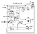
- FIG. 2 is a control block diagram for calculating the target engine operating point and the target power.
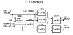
- FIG. 3 is a control block diagram for calculating a torque command value.
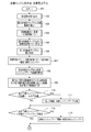
- FIG. 4 is a flowchart for calculating the target engine operating point and the target power.
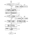
- FIG. 5 is a flowchart for calculating the target engine operating point and the target power following FIG.
- FIG. 6 is a flowchart for calculating a torque command value.
- FIG. 7 is a diagram showing the engine rotation speed for each vehicle speed during the upper limit rotation of the first motor generator. (Example) FIG.
- FIG. 8 is a diagram showing the relationship between the accelerator opening and the target engine power.
- FIG. 9 is a diagram showing a power upper and lower limit limit search table based on battery temperature.
- FIG. 10 is a diagram showing a power upper / lower limit limit search table based on battery voltage.
- FIG. 11 is a diagram showing a power upper and lower limit limit value search table according to the state of charge (SOC).
- FIG. 12 is a diagram showing a power loss search map.
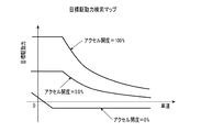
- FIG. 13 is a diagram showing a target driving force search map.
- FIG. 14 shows a target charge / discharge power search table.
- FIG. 9 is a diagram showing a power upper and lower limit limit search table based on battery temperature.
- FIG. 10 is a diagram showing a power upper / lower limit limit search table based on battery voltage.
- FIG. 11 is a diagram showing a power upper and lower limit limit value search table according to the state of charge (SOC).
- SOC state of charge
- FIG. 12 is
- FIG. 15 is a diagram showing a target operating point search map.
- FIG. 16 is a collinear diagram when the vehicle is changed at the same engine operating point.
- FIG. 17 is a diagram showing each efficiency state on the equal power line.
- FIG. 18 is a collinear diagram showing each point (D, E, F) on the equal power line.
- FIG. 19 is a diagram showing the best line for engine efficiency and the best line for overall efficiency.
- FIG. 20 is a collinear diagram of the LOW gear ratio state.
- FIG. 21 is a collinear diagram of the intermediate gear ratio state.
- FIG. 22 is a collinear diagram of the HIGH gear ratio state.
- FIG. 23 is a collinear diagram in a state where power circulation occurs.
- the present invention requires a large driving force while achieving both the protection of the internal combustion engine with restrictions on the engine operating point and satisfying the driving force required by the driver by power assist using battery power.
- To meet the demands of the engine when it is being used to correct the target engine power to account for battery conditions to prevent overcharging of the battery, and to consider the power loss of multiple motor generators
- the lower limit of the target engine power is limited to control a plurality of motor generators. This is achieved by correcting the target power to correct the lower limit, and further correcting the target power based on the power loss to correct the lower limit. It is intended.
- reference numeral 1 denotes a drive control device for a hybrid vehicle as an electric vehicle.
- the drive control device 1 includes an output shaft 3 of an internal combustion engine (denoted as “ENG” in the drawing) 2 that is a driving source that outputs torque, and a first motor generator (in the drawing as a plurality of motor generators (electric motors)).
- ENG internal combustion engine
- MG1 motor generator
- MG2 second motor generator
- OUT a drive shaft
- a one-way clutch 10 is provided in the middle of the output shaft 3 of the internal combustion engine 2 on the internal combustion engine 2 side. This one-way clutch 10 prevents the internal combustion engine 2 from rotating in the reverse direction, and receives the torque reaction force of the second motor generator 5 during EV (electric vehicle) travel.
- the first motor generator 4 includes a first rotor 11 and a first stator 12.
- the second motor generator 5 includes a second rotor 13 and a second stator 14.
- the drive control device 1 also includes a first inverter 15 that controls the operation of the first motor generator 4, a second inverter 16 that controls the operation of the second motor generator 5, a first inverter 15, and a second inverter.
- Control means (drive control unit: ECU) 17 communicated with the inverter 16 is provided.
- the first inverter 15 is connected to the first stator 12 of the first motor generator 4.
- the second inverter 16 is connected to the second stator 14 of the second motor generator 5.
- Each power supply terminal of the first inverter 15 and the second inverter 16 is connected to a battery (driving high voltage battery) 18.
- the battery 18 can exchange power with the first motor generator 4 and the second motor generator 5.
- the hybrid vehicle is driven and controlled using outputs from the internal combustion engine 2, the first motor generator 4, and the second motor generator 5.
- the power transmission mechanism 9 is a so-called four-shaft power input / output device, which includes the output shaft 3 and the drive shaft 8 of the internal combustion engine 2, and the first motor generator 4 and the drive shaft on the internal combustion engine 2 side. 8 side second motor generator 5 is arranged, the power of internal combustion engine 2, the power of first motor generator 4 and the power of second motor generator 5 are combined and output to drive shaft 8. Power is exchanged among the engine 2, the first motor generator 4, the second motor generator 5, and the drive shaft 8. As shown in FIG. 7, the four rotation elements of the power transmission mechanism 9 are a rotation element connected to the first motor generator (MG1) 4, a rotation element connected to the internal combustion engine (ENG) 2, and a drive shaft.
- MG1 first motor generator
- ENG internal combustion engine
- the rotating elements connected to (OUT) 8 and the rotating elements connected to the second motor generator (MG2) 5 are arranged in this order, and the mutual lever ratios between these elements are set in the same order, k1: 1: k2 is provided, the torque correction value of the first motor generator 4 and the torque correction value of the second motor generator 5 are multiplied by the torque correction value of the first motor generator 4 by k1, and the second motor
- the torque correction value of the generator 5 is set so as to maintain a relationship equal to a value obtained by multiplying (1 + k2).
- k1 Lever ratio between the first motor generator (MG1) and the internal combustion engine (ENG) when “1” is set between the internal combustion engine (ENG) and the drive shaft (OUT)
- k2 Internal combustion engine (ENG)-drive shaft The lever ratio between the drive shaft (OUT) and the second motor generator (MG2) when the distance between (OUT) is “1”.
- the power transmission mechanism 9 is configured by arranging a first planetary gear mechanism 19 and a second planetary gear mechanism 20 in which two rotation elements are connected to each other.
- the first planetary gear mechanism 19 includes a first sun gear 21, a first pinion gear 22 meshed with the first sun gear 21, and a first ring gear 23 meshed with the first pinion gear 22.
- the first carrier 24 connected to the first pinion gear 22 and the output gear 25 connected to the first ring gear 23 are provided.
- the second planetary gear mechanism 20 includes a second sun gear 26, a second pinion gear 27 meshed with the second sun gear 26, and a second ring gear 28 meshed with the second pinion gear 27. And a second carrier 29 connected to the second pinion gear 27.
- the first carrier 24 of the first planetary gear mechanism 19 is connected to the output shaft 3 of the internal combustion engine 2.
- the second carrier 29 of the second planetary gear mechanism 20 is connected to the first ring gear 23 and the output gear 25 of the first planetary gear mechanism 19.
- the first rotor 11 of the first motor generator 4 is connected to the first sun gear 21 via the first motor output shaft 30.
- the output shaft 3 of the internal combustion engine 2 is connected to the first carrier 24 and the second sun gear 26.
- the drive shaft 8 is connected to the first ring gear 23 and the second carrier 29 via the output gear 25 and the output transmission mechanism 7.
- the second rotor 13 of the second motor generator 5 is connected to the second ring gear 28 via the second motor output shaft 31.
- the second motor generator 5 includes a second motor output shaft 31, a second ring gear 28, a second carrier 29, a first ring gear 23, an output gear 25, an output transmission mechanism 7, and a drive shaft 8.
- the vehicle can be directly connected to the drive wheels 6, and the vehicle can be driven with only a single output. That is, in the power transmission mechanism 9, the first carrier 24 of the first planetary gear mechanism 19 and the second sun gear 26 of the second planetary gear mechanism 20 are coupled and connected to the output shaft 3 of the internal combustion engine 2.
- the first ring gear 23 of the first planetary gear mechanism 19 and the second carrier 29 of the second planetary gear mechanism 20 are coupled and connected to the drive shaft 8.
- the first motor generator 4 is connected to the first sun gear 21, the second motor generator 5 is connected to the second ring gear 28 of the second planetary gear mechanism 20, the internal combustion engine 2, the first motor generator 4, power is exchanged between the second motor generator 5 and the drive shaft 8.
- the control means 17 includes an accelerator opening detection means 32 for detecting the depression amount of the accelerator pedal as an accelerator opening, a vehicle speed detection means 33 for detecting the vehicle speed, and a battery charging state for detecting the state of charge (SOC) of the battery 18.
- the detection means 34 and the engine rotation speed detection means 35 for detecting the engine rotation speed communicate with each other.
- an air amount adjustment mechanism 36, a fuel supply mechanism 37, and an ignition timing adjustment mechanism 38 communicate with the control means 17 so as to control the internal combustion engine 2.
- the control means 17 communicates with a battery state detection means 39 for detecting a battery state (parameters such as battery temperature and battery voltage).
- the control means 17 includes a target drive force setting means 17A, a target drive power setting means 17B, a target charge / discharge power setting means 17C, a temporary target engine power calculation means 17D, and a provisional Target engine operating point setting means 17E, target engine operating point setting means 17F, target engine power setting means 17G, target engine power lower limit value calculating means 17H, power upper and lower limit value calculating means 17I, and power loss estimating means 17J
- the target power calculation means 17K and the motor torque command value calculation means 17L are provided. Further, as shown in FIG.
- a target charge / discharge power setting unit 17C and a power loss estimation unit 17J are connected to the provisional target engine power calculation unit 17D via an addition / subtraction calculation unit 17M.
- the target driving force setting means 17A sets the target driving force based on the accelerator opening detected by the accelerator opening detecting means 32 and the vehicle speed detected by the vehicle speed detecting means 33.
- the target drive power setting means 17B sets the target drive power based on the accelerator opening detected by the accelerator opening detection means 32 and the vehicle speed detected by the vehicle speed detection means 33.
- the target charge / discharge power setting means 17C sets the target charge / discharge power based on at least the battery charge state detected by the battery charge state detection means 34.
- the temporary target engine power calculation unit 17D calculates the temporary target engine power from the target drive power set by the target drive power setting unit 17B and the target charge / discharge power set by the target charge / discharge power setting unit 17C.
- the temporary target engine operating point setting means 17E sets a temporary target engine operating point for determining the temporary target engine rotational speed and the temporary target engine torque from the temporary target engine power calculated by the temporary target engine power calculating means 17D and the search map M. To do.
- the target engine operating point setting unit 17F is based on the vehicle speed detected by the vehicle speed detecting unit 33 and the temporary target engine rotational speed and the temporary target engine torque calculated by the temporary target engine operating point setting unit 17E. And a target engine operating point for determining a target engine torque.
- the target engine power setting means 17G calculates the target engine power from the target engine operating point set by the target engine operating point setting means 17F.
- the target engine power lower limit calculating means 17H calculates a target engine power lower limit based on the accelerator opening or a target driving force calculated from the accelerator opening.
- the power upper and lower limit value calculation means 17I sets a power upper limit value and a power lower limit value for limiting input / output power to the battery 18 based on the battery state detected by the battery state detection means 39.
- the power loss estimation unit 17J calculates an estimated power that is a power loss based on the vehicle speed and the target driving force.
- the target power calculation means 17K calculates the target power from the difference between the target engine power calculated based on the provisional target engine operating point and the target drive power.
- the motor torque command value calculating means 17L sets the torque command values of the plurality of motor generators 4 and 5 based on the temporary target engine operating point set by the temporary target engine operating point setting means 17E. Further, torque command values of the plurality of motor generators 4 and 5 are calculated using a torque balance formula including a target engine torque obtained from the target engine operating point and a power balance formula including a target power.
- the temporary target engine power calculation means 17D calculates the temporary target engine power calculated from the target drive power set by the target drive power setting means 17B and the target charge / discharge power set by the target charge / discharge power setting means 17C. When the temporary target engine power is smaller than the target engine power lower limit value, the target engine power lower limit value is set as the temporary target engine power and the temporary target engine power is output.
- the provisional target engine power calculation means 17D finally calculates the provisional target engine power based on the accelerator opening, and inputs the target engine power lower limit value from the target engine power lower limit value calculation means 17H.
- the provisional target engine power is compared with the target engine power lower limit, and if the provisional target engine power is equal to or greater than the target engine power lower limit, the provisional target engine power is maintained, while the provisional target engine power is If it is smaller than the power lower limit value, the target engine power lower limit value is corrected so as to be limited based on the power lower limit value by setting the target engine power lower limit value as the provisional target engine power. Further, the provisional target engine power calculation means 17D basically calculates the provisional target engine power based on the target drive power, the target charge / discharge power, and the estimated power as the power loss, and the target engine power lower limit value calculation means. Limit with the target engine power lower limit from 17H.
- the provisional target engine power is determined in consideration of power loss, and the target engine power lower limit value also considers power loss.
- the target engine power lower limit value is a limit value that reflects the battery state, and therefore is wasted. It is not a double calculation.
- the provisional target engine power calculation means 17D is provided with a target engine power maximum value corresponding to a state in which the target drive power is receiving power assist depending on the power of the battery 18, and a target drive power setting.
- the provisional target engine power calculated from the target drive power set by the means 17B and the target charge / discharge power set by the target charge / discharge power setting means 17C is compared with the target engine power maximum value, and the smaller one of them is calculated. Update as provisional target engine power.
- the state of charge (SOC) of the battery 18 can be within a predetermined range, and a power assist region using the power of the battery 18 can be provided. . Further, it is possible to drive using the electric power of the battery 18 by using the power assist area according to the driver's request. Further, it is possible to control the plurality of motor generators 4 and 5 when the battery 18 is charged / discharged.
- the provisional target engine operating point calculation means 17E becomes the target engine operating point as it is when the provisional target engine operating point is not limited by the upper limit rotational speed or the like. For this reason, the temporary target engine operating point calculation means 17E can be configured as the target engine operating point calculation means 17F. That is, for convenience, the provisional target engine operating point calculation unit 17E is described separately from the target engine operating point calculation unit 17F. However, the provisional target engine operating point calculation unit 17E may be used as the target engine operation point calculation unit 17F. .
- the target engine power lower limit value calculation means 17H corrects the target engine power lower limit value to be limited based on the power lower limit value, and outputs the target engine power lower limit value to the provisional target engine power calculation means 17D. Further, the target engine power lower limit value calculating means 17H corrects the power lower limit value using the estimated power that causes power loss, and corrects the target engine power lower limit value so as to limit based on the corrected power lower limit value. And the target engine power lower limit value is output to the provisional target engine power calculation means 17D. Further, the target engine power lower limit value calculating unit 17H is configured to perform the target engine power lower limit value based on the accelerator opening that reflects the driver's intention in a basic case where correction of the power lower limit value depending on the battery state is not necessary.
- the value is calculated (see FIG. 8). Further, the target engine power lower limit value calculating means 17H inputs the power lower limit value that is output from the power upper and lower limit value calculating means 17I and is calculated so as to limit the input / output of the battery 18, and this power lower limit value. The absolute value of the value (reverse encoding) and the target engine power lower limit value are compared in magnitude. If the target engine power lower limit value is equal to or greater than the absolute value of the power lower limit value, the target engine power lower limit value is retained.
- the target engine power lower limit value calculating unit 17H corrects the target engine power lower limit value so as to limit based on the power lower limit value. It is possible to configure in this way by calculating the power loss in a separate process without including the power loss (see FIGS. 9 to 11).
- the target engine power lower limit calculating means 17H receives the estimated power that causes power loss, and corrects the absolute value (reverse encoding) of the power lower limit corrected so as to exclude the estimated power from the power lower limit and the target engine.
- the power lower limit value is compared, and if the target engine power lower limit value is equal to or greater than the absolute value of the power lower limit value, the target engine power lower limit value is retained, while the target engine power lower limit value is the absolute value of the power lower limit value. Is smaller than the absolute value of the power lower limit value as the target engine power lower limit value, and the final target engine power lower limit value is output to the provisional target engine power calculation means 17D.
- the target engine power lower limit value calculation unit 17H corrects the power lower limit value using the estimated power that causes power loss, and corrects the target engine power lower limit value to limit based on the corrected power lower limit value. (See FIG. 12). Further, the target engine power lower limit value calculating means 17H is configured to calculate the target engine power lower limit value based on the accelerator opening, but based on the target driving force calculated based on the accelerator opening, the target engine power is calculated. It is good also as a structure which calculates a lower limit. Both of these cases are common in that the driver's required driving force is reflected based on the accelerator opening.
- the power upper and lower limit value calculation means 17I includes a table (see FIG. 9) that defines the power upper limit value and the power lower limit value with respect to the battery temperature, and a table (see FIG. 10) that defines the power upper limit value and the power lower limit value with respect to the battery voltage. And a table (see FIG. 11) that defines the power upper limit value and the power lower limit value for the state of charge (SOC) of the battery 18.
- the battery temperature and battery voltage as the battery state and the state of charge (SOC) are input, and the power upper limit value and power lower limit value specified based on the input battery temperature and the input battery voltage are specified.
- the power upper limit value and the power lower limit value and the power upper limit value and the power lower limit value defined based on the input state of charge (SOC) are obtained, and the estimated power subtracting the power loss is subtracted to obtain the respective power upper limit value and power.
- the lower limit values are compared with each other, and the power upper limit value and the power lower limit value having the largest restrictions are output to the target power calculation means 17K.
- the power loss estimation means 17J includes a search map (see FIG. 12) in which estimated power as power loss is set. As shown in FIG. 12, the estimated power as the power loss increases as the target driving force increases, and the increase rate increases as the target driving force increases. Further, the estimated power as power loss increases as the vehicle speed increases, and the target driving force that takes the maximum value decreases as the vehicle speed increases.
- the target power calculation means 17K can be configured to limit the target power to the power upper limit value or the power lower limit value when the target power is out of the range set by the power upper limit value and the power lower limit value.
- the motor torque command value calculating means 17L uses the torque correction value of the first motor generator 4 and the torque correction value of the second motor generator 5 in the plurality of motor generators as the actual engine. While calculating based on the deviation between the rotational speed and the target engine rotational speed, the ratio between the torque correction value of the first motor generator 4 and the torque correction value of the second motor generator 5 is calculated as the lever of the power transmission mechanism 9. A predetermined ratio based on the ratio is set. As a result, the torque balance of the internal combustion engine 2 is canceled out using the torque balance formula focusing on the torque change with the drive shaft 8 as a fulcrum. The torque can be prevented from being affected.
- the motor torque command value calculating means 17L uses the torque balance equation including the target engine torque obtained from the target engine operating point and the electric power balance equation including the target charge / discharge power.
- the respective torque command values of the motor generator 5 are calculated, and the first motor generator 4 and the second motor generator 5 are made to converge the actual engine rotational speed to the target engine rotational speed obtained from the target engine operating point.
- Each feedback correction can be performed on the torque command value.
- the power of the first motor generator 4 and the second motor generator 5 In the hybrid vehicle that drives the drive shaft 8 connected to the drive wheels 6 by combining the outputs of the internal combustion engine 2, the power of the first motor generator 4 and the second motor generator 5, The value of the driving force obtained by adding the power assist due to is set in advance as the maximum value of the target driving force, and the target driving power is calculated from the target driving force using the accelerator opening and the vehicle speed as parameters, and the vehicle speed.
- the lower limit of the target engine power is limited according to the driving force or the accelerator opening, and the lower limit value is limited according to the input limit of the battery 18 and the power loss of the first motor generator 4 and the second motor generator 5.
- a value obtained by obtaining the target charge / discharge power based on the 18 state of charge (SOC) and adding it to the target drive power is obtained as the provisional target engine power. If the engine speed at the provisional target engine operating point exceeds the upper limit of the engine speed calculated based on the vehicle speed, the engine speed at the engine operating point is changed to the upper limit value. In addition, the engine operating point torque is changed to a value corresponding to the engine speed after the change to obtain the target engine operating point, the target engine power is calculated from the target engine operating point, and the target drive power and target engine power are calculated.
- a target power that is a target value of input / output power from the battery 18 is obtained, and the first motor generator 4 and the second motor are determined by a torque balance formula including the target engine torque and a power balance formula including the target power.
- the torque command value of the generator 5 is calculated.
- the operating point (engine operating point) of the internal combustion engine 2 it is possible to achieve both the target driving force and the target charge / discharge. Further, by finely correcting the torque command values of the plurality of motor generators 4 and 5, the engine speed can be quickly converged to the target value.
- the engine operating point can be combined with the target operating point, an appropriate operating state can be achieved. Further, as control of the plurality of motor generators 4 and 5 when the battery 18 is charged / discharged in a hybrid vehicle including the internal combustion engine 2 and the plurality of motor generators 4 and 5, the operating point of the internal combustion engine 2 (engine operating point) ), When performing control to ensure both the target driving force and the target charge / discharge, the torque fluctuation of the internal combustion engine 2 is optimized so as not to affect the driving torque, and drivability and traveling are optimized. Feeling can be improved.
- the operating point (engine operating point) of the internal combustion engine 2 considering the operating point (engine operating point) of the internal combustion engine 2, securing the target driving force in the plurality of motor generators 4, 5 and securing the charging / discharging in the vicinity of the target while preventing overcharging / discharging of the battery 18. And both.
- a target power different from the target charge / discharge power is set based on that, and the optimized target engine operating point is set.
- driving power of the plurality of motor generators 4 and 5 are set based on the optimum target power that prevents overcharge / discharge, and thus the internal combustion engine 2 is protected by limiting the engine rotation speed and the battery.
- the driving assist required by the driver can be satisfied by power assist using 18 electric power.
- the engine speed at the time of the upper limit rotation of the first motor generator 4 is set for each vehicle speed.
- the calculation of the target engine operating point (target engine speed, target engine torque) and the target power from the accelerator opening and the vehicle speed are shown in the control block diagram of FIG. 2 and the flowcharts of FIGS. This will be explained based on.
- various signals acceleration position, vehicle speed, state of charge (SOC), battery state (battery temperature, battery voltage, etc.) used for control are used.
- the target driving force corresponding to the accelerator opening and the vehicle speed is calculated from the target driving force search map shown in Fig. 13 (step 103) In this case, the accelerator opening is zero (0).
- a target drive power necessary for driving the vehicle with the target drive force is set by multiplying the target drive force and the vehicle speed (step 104). Further, in order to control the state of charge (SOC) of the battery 18 within the normal use range, the target charge / discharge power is calculated from the target charge / discharge amount search table shown in FIG. 14 (step 105).
- the charging power is increased to prevent overdischarge of the battery 18, and when the state of charge (SOC) of the battery 18 is high, the discharge power is increased. It is made larger to prevent overcharging.
- the discharge side is treated as a positive value and the charge side is treated as a negative value.
- the estimated power that is the power loss in the first motor generator 4 and the second motor generator 5 is searched from the power loss search map shown in FIG. 12 (step 106). At this time, since the operating points of the first motor generator 4 and the second motor generator 5 are not yet determined, the electric power is determined from the power loss search map of the first motor generator 4 and the second motor generator 5 in FIG. Loss cannot be calculated.
- an approximate value of power loss is set in advance using the vehicle speed and the target driving force as parameters, and is calculated by searching. Then, a temporary target engine power that is a power to be output from the internal combustion engine 2 is calculated from the target drive power, the target charge / discharge power, and the estimated power that is the power loss (step 107).
- the provisional target engine power to be output from the internal combustion engine is a value obtained by adding (subtracting in the case of discharging) the power required to drive the vehicle to charge the battery 13.
- the target charge / discharge power is subtracted from the target drive power to calculate the provisional target engine power.
- a preset target engine power lower limit value is calculated from the relationship between the accelerator opening and the target engine power in accordance with the target driving force or the accelerator opening (step 108).
- the relationship between the target engine power lower limit value and the accelerator opening is shown by a solid line in FIG.
- the power upper limit value and the power lower limit value are calculated from the power upper and lower limit limit search tables shown in FIGS. 9 to 11 (step 109).
- the discharge side is treated as a positive value
- the charge side is treated as a negative value
- the minimum value on the discharge side among the values calculated from each search table is the power upper limit value.
- the value with the smallest absolute value on the charging side is calculated as the power lower limit value.
- FIG. 10 shows an example of restriction by battery temperature. When the battery temperature is low, the reaction speed of the battery 18 decreases, so that the chargeable / dischargeable power is reduced. Further, when the battery temperature is high, it is necessary to limit the charge / discharge power in order to prevent the temperature from rising.
- FIG. 10 shows an example of restriction by battery temperature. When the battery temperature is low, the reaction speed of the battery 18 decreases, so that the chargeable / dischargeable power is reduced. Further, when the battery temperature is high, it is necessary to limit the charge / discharge power in order to prevent the temperature from rising.
- FIG. 11 shows an example of restriction by battery voltage.
- the battery 18 has an upper limit voltage and a lower limit voltage for protection. If the battery 18 is used beyond that range, the battery 18 will deteriorate. Therefore, it is necessary to limit charging when the voltage is high, and limit discharging when the voltage is low.
- FIG. 12 shows an example of restriction by the state of charge (SOC) of the battery 18.
- SOC state of charge
- the state of charge (SOC) of the battery 18 must not be overdischarged or overcharged. When the state of charge (SOC) is low, the discharge is limited, and when the state of charge (SOC) is high, the battery 18 is charged. Need to be restricted. Then, it is determined whether or not the provisional target engine power lower limit value is less than the power lower limit value (step 110).
- step 110 If this step 110 is YES and the provisional target engine power lower limit value is less than the power lower limit value, the provisional target engine power lower limit value is limited to the power lower limit value (step 111) ("final lower limit value in FIG. Value ").
- step 112 it is determined whether or not the provisional target engine power is less than the provisional target engine power lower limit value (step 112). If this step 112 is YES, the temporary target engine power is limited to the temporary target engine power lower limit value (step 113).
- step 114 it is determined whether or not the provisional target engine power is larger than the upper limit power.
- This upper limit power is the maximum value that the internal combustion engine 2 can output. If this step 114 is YES, the temporary target engine power is limited to the upper limit power and the upper limit guard is applied (step 115). If this step 114 is NO, or after the processing of step 115, the temporary target engine operating point corresponding to the temporary target engine power and the vehicle speed is calculated from the target engine operating point search map shown in FIG. 116). As shown in FIG.
- the target engine operating point search map is composed of the power transmission mechanism 9, the first motor generator 4, and the second motor generator 5 for the efficiency of the internal combustion engine 2 on the equal power line.
- a line that selects and connects the points where the overall efficiency, which takes into account the efficiency of the power transmission system to be improved, for each power is set as a target operating point line.
- the target operating point line is set for each vehicle speed. This set value may be obtained experimentally, or may be obtained by calculating from the efficiency of the internal combustion engine 2, the first motor generator 4, and the second motor generator 5.
- the target operating point line is set to move to the high rotation side as the vehicle speed increases. This is due to the following reason. When the same engine operating point is set as the target engine operating point regardless of the vehicle speed, as shown in FIG.
- the first motor generator 4 operates as an electric motor
- the second motor generator 5 operates as a generator
- power circulation is generated.
- the efficiency of the transmission system decreases. Therefore, as shown at point C in FIG. 17, even if the engine efficiency is good, the efficiency of the power transmission system is lowered, and the overall efficiency is lowered. Therefore, in order to prevent the power circulation from occurring in the high vehicle speed range, the rotational speed of the first motor generator 4 is set to zero (0) or more as shown by a point E in the alignment chart shown in FIG. Although it does so, the engine operating point moves in the direction where the engine rotation speed becomes higher. Therefore, as shown in the point E of FIG.
- FIG. 17 shows the three operating points, point C, point D, and point E, on the target operating point search map.
- FIG. 19 when the vehicle speed is high, it is clear that the engine operating point where the overall efficiency is the best moves to the higher rotation side than the operating point where the engine efficiency is the best.
- the engine upper limit rotational speed is calculated from the vehicle speed (step 117).
- the upper limit rotational speed of the internal combustion engine 2 is limited by the upper limit rotational speed of the first motor generator 4, and its value is a value corresponding to the vehicle speed (the rotational speed of the drive shaft 8).
- the temporary target engine operating point temporary target engine speed and temporary target engine torque
- the target engine operating point target engine speed and target engine torque
- step 120 the engine upper limit rotational speed is used as the target engine rotational speed (step 120), and the target engine torque at this target engine rotational speed is calculated from the target operating point search map of FIG. (Step 121).
- the target engine power is calculated from the target engine operating point (target engine speed and target engine torque) (step 122).
- the target engine power becomes a value smaller than the calculated temporary target engine power, that is, a value that can actually be output. Then, the target engine power is subtracted from the target drive power to calculate the target power (step 123).
- the target power when the target drive power is larger than the target engine power, the target power is a value that means assist power by battery power.
- the target power when the target engine power is larger than the target drive power, the target power is a value that means charging power to the battery 18.
- the target engine power is a value that can be actually output, the driving force requested by the driver can be obtained by performing power assist with the target power calculated here. Then, the program is returned (step 124).
- step 201 when the program of the control means 17 is started (step 201), first, the rotational speed No of the first planetary gear mechanism 19 and the second planetary gear mechanism 20 is calculated from the vehicle speed, and then the engine When the rotational speed reaches the target engine rotational speed Net, the target rotational speed Nmglt of the first motor generator 4 and the target rotational speed Nmg2t of the second motor generator 5 are calculated (step 202).
- the rotation speed Nmglt of the first motor generator 4 and the rotation speed Nmg2t of the second motor generator 5 are calculated by the following (Expression 1) and (Expression 2). This arithmetic expression is obtained from the relationship between the rotational speeds of the first planetary gear mechanism 19 and the second planetary gear mechanism 20.
- Nmglt (Net-No) * k1 + Net (Formula 1)
- Nmg2t (No-Net) * k2 + No ... (Formula 2)
- k1 Lever ratio between the first motor generator (MG1) and the engine (ENG) when the distance between the engine (ENG) and the drive shaft (OUT) is "1”
- k2 Engine (ENG)-drive shaft (OUT)
- the lever ratio between the drive shaft (OUT) and the second motor generator (MG2) when the interval is set to “1”. That is, k1 and k2 are values determined by the gear ratio of the first planetary gear mechanism 19 and the second planetary gear mechanism 20.
- the basic torque Tmgli of the first motor generator 4 is calculated from the rotation speed Nmg1t of the first motor generator 4, the rotation speed Nmg2t of the second motor generator 5, the target charge / discharge power Pbatt, and the target engine torque Tet (step). 203).
- This basic torque Tmgli is calculated by the following calculation formula (3).
- Tmgli (Pbatt * 60 / 2 ⁇ Nmg2t * Tet / k2) / (Nmglt + Nmg2t * (1 + k1) / k2) (Formula 3)
- This (Expression 3) represents the balance of torque input to the first planetary gear mechanism 19 and the second planetary gear mechanism 20 shown below (shown by “(Expression 4)” below) (torque balance expression ), And the power generated or consumed by the first motor generator 4 and the second motor generator 5 is equal to the input / output power (Pbatt) to the battery 18 (in the following “(Equation 5)”) It can be derived by solving simultaneous equations consisting of (power balance equation).
- the target torque and the target engine torque of the first motor generator 4 and the second motor generator 5 are set to the first motor generator 4,
- the balance is based on the lever ratio based on the gear ratio of the power transmission mechanism 9 that mechanically operatively connects the second motor generator 5 and the internal combustion engine 2.
- Nmg1 * Tmg1 * 2 ⁇ / 60 + Nmg2 * Tmg2 * 2 ⁇ / 60 Pbatt (Formula 5)
- the basic torque Tmg2i of the second motor generator 5 is calculated from the basic torque Tmgli and the target engine torque by the following (Equation 6) (step 204).
- Tmg2i (Tet + (1 + k1) * Tmg1i) / k2 (Equation 6)
- the feedback correction amounts set for the torque command values of the first motor generator 4 and the second motor generator 5 are the first motor generator 4, the second motor generator 5, the drive shaft 8, the internal combustion engine 2, and the like. Are set in association with each other on the basis of the gear ratio or lever ratio of the power transmission mechanism 9 having four rotating elements connected to each other.
- the feedback correction torques Tmglfb and Tmg2fb are added to the basic torques Tmgli and Tmg2i to calculate the torque command value Tmg1 of the first motor generator 4 and the torque command value Tmg2 of the second motor generator 5 (step 206). ).
- k1 and k2 are defined as follows.
- k1 ZR1 / ZSl
- k2 ZS2 / ZR2 here
- ZS1 Number of teeth of the first sun gear
- ZR1 Number of teeth of the first ring gear
- ZS2 Number of teeth of second sun gear
- ZR2 Number of teeth of the second ring gear It is.
- the rotation speed is the positive direction of the rotation direction of the internal combustion engine 2
- the torque input and output to each axis is the same direction as the torque of the internal combustion engine 2. Define the direction to be positive.
- the first inverter 15 is used when the first motor generator 4 and the second motor generator 5 perform power generation or power running (acceleration is transmitted to wheels (drive wheels) to accelerate or keep an equilibrium speed with an upward gradient). Loss due to heat generation in the second inverter 16 and the first motor generator 4 and the second motor generator 5 occurs, so that the efficiency when converting between electric energy and mechanical energy is 100% However, for the sake of simplicity, the description will be made assuming that there is no loss.
- the second motor generator 5 is not powered or regenerated, and the torque command value Tmg2 of the second motor generator 5 is zero (0). Further, the ratio between the engine rotation speed and the rotation speed of the drive shaft 8 is k1 / (1 + k1). (4) State in which power circulation is occurring (see FIG. 23) In a state where the vehicle speed is higher than the HIGH gear ratio state of FIG. 22, the first motor generator 4 is reversely rotated. In this state, the first motor generator 4 is powered and consumes power. Therefore, when the battery 18 is not charged / discharged, the second motor generator 5 is regenerated to generate power.
- control means 17 determines the provisional target engine from the target drive power set by the target drive power setting means 17B and the target charge / discharge power set by the target charge / discharge power setting means 17C.
- Provisional target engine power calculation means 17D for calculating power
- target engine power lower limit value calculation means 17H for calculating a target engine power lower limit value based on the accelerator opening or a target driving force calculated from the accelerator opening
- provisional The target power calculating means 17K for calculating the target power from the difference between the target engine power calculated based on the target engine operating point and the target driving power, and the temporary target engine operating point set by the temporary target engine operating point setting means 17E.
- the temporary target engine power calculation means 17D calculates the temporary target engine power calculated from the target drive power set by the target drive power setting means 17B and the target charge / discharge power set by the target charge / discharge power setting means 17C. When the temporary target engine power is smaller than the target engine power lower limit value, the target engine power lower limit value is set as the temporary target engine power and the temporary target engine power is output.
- the motor torque command value calculation means 17L uses the torque balance formula including the target engine torque obtained from the target engine operating point and the power balance formula including the target power to calculate the torque command values of the plurality of motor generators 4 and 5, respectively. calculate.
- the control unit 17 includes a power upper / lower limit value calculation unit 17I for setting a power upper limit value and a power lower limit value for limiting input / output power to the battery 18 based on the battery state. .
- the target engine power lower limit calculation means 17H corrects the target engine power lower limit value to be limited based on the power lower limit value, and outputs the target engine power lower limit value to the provisional target engine power calculation means 17H. Thereby, the overdischarge and overload with respect to the battery 18 can be prevented by setting the lower limit according to the battery state. Further, in a state where the increased output is continuously maintained, it can be limited by a lower limit value corresponding to the battery state.
- the control means 17 includes power loss estimation means 17J for calculating an estimated power that becomes a power loss based on the vehicle speed and the target driving force.
- the target engine power lower limit value calculating means 17H corrects the power lower limit value using the estimated power that causes power loss, corrects the target engine power lower limit value so as to limit based on the corrected power lower limit value, and provisional
- the target engine power lower limit value is output to the target engine power calculation means 17D.
- the drive control device is not limited to a hybrid vehicle but can be applied to other electric vehicles such as an electric vehicle.
Landscapes
- Engineering & Computer Science (AREA)
- Chemical & Material Sciences (AREA)
- Combustion & Propulsion (AREA)
- Transportation (AREA)
- Mechanical Engineering (AREA)
- Automation & Control Theory (AREA)
- Hybrid Electric Vehicles (AREA)
- Electric Propulsion And Braking For Vehicles (AREA)
Abstract
Description
このハイブリッド車両には、シリーズ方式(内燃機関は発電機を回すためのみに用いられ、駆動は全てモータジェネレータで行う方式:直列方式)やパラレル方式(内燃機関とモータジェネレータとが並列に配置され、夫々の動力が駆動に用いられる方式:並列方式)がある。
また、ハイブリッド車両には、これらシリーズ方式やパラレル方式の他の方式で、3軸式の動力伝達機構として、1つの遊星歯車機構(3つの回転要素を有する差動歯車機構)と、モータジェネレータとしての2つのモータジェネレータ(第一のモータジェネレータ:MG1、第二のモータジェネレータ:MG2)とを用いて内燃機関の動力を発電機と駆動軸とに分割し、発電機で発電した電力を用いて駆動軸に設けたモータジェネレータを駆動することにより、内燃機関の動力をトルク変換する方式のものがある(特許第3050125号公報、特許第3050138号公報、特許第3050141号公報、特許第3097572号公報)。
これにより、ハイブリッド車両では、内燃機関の動作点(エンジン動作点)を、停止が含められた任意の点に設定することができ、燃費を向上している。
この点を解決する方法としては、4軸式の動力伝達機構として、4つの回転要素を有する動力伝達機構(差動歯車機構)の各回転要素に、内燃機関の出力軸、第一のモータジェネレータ、第二のモータジェネレータ、及び駆動輪に接続される駆動軸を接続し、内燃機関の動力と第一のモータジェネレータ・第二のモータジェネレータの動力とを合成して駆動軸に出力する構造がある。そして、共線図上において内側の回転要素に内燃機関の出力軸と駆動軸とを配置し、共線図上において外側の回転要素には内燃機関側の第一のモータジェネレータと駆動軸側の第二のモータジェネレータとを配置することにより、内燃機関から駆動軸へ伝達される動力のうち第一のモータジェネレータ及び第二のモータジェネレータが受け持つ割合を少なくし、第一のモータジェネレータ及び第二のモータジェネレータを小型化するとともに、駆動装置としての伝達効率を改善しているものがある(特開2004-15982号公報、特開2002-281607号公報)。
また、4軸式の動力伝達機構には、上記の構造と同様の方法であり、さらに、5つ目の回転要素を加え、この5つ目の回転要素の回転を停止させるブレーキ機構を設けた構造がある(特許第3578451号公報)。
上記の特許第3050125号公報に記載の3軸式の動力伝達機構においては、車両に要求される駆動力とバッテリの充電に要求される電力を加算して内燃機関が出力すべきパワーを算出し、そのパワーとなるトルクとエンジン回転速度との組み合わせの中からできるだけ効率が良いポイントを算出して目標エンジン動作点としている。そして、エンジン動作点が目標エンジン動作点となるように、第一のモータジェネレータを駆動制御してエンジン回転速度を制御している。
しかし、4軸式の動力伝達機構の場合には、駆動軸と第二のモータジェネレータとが別々の軸となり、第二のモータジェネレータのトルクもトルクバランスに影響してエンジン回転速度の制御に影響するため、上記の3軸式の動力伝達機構の制御方法を使用することができなかった。
また、上記の特開2004-15982号公報に記載の4軸式の動力伝達機構の場合には、バッテリヘの充放電の無い状態で走行する場合の第一のモータジェネレータ、第二のモータジェネレータのトルクをトルクバランス式から算出し、エンジン回転速度をフィードバック制御して、エンジン回転速度と駆動力とを制御しているが、バッテリヘの充放電がある場合、例えば、バッテリの電力によるパワーアシストを行う場合の制御については言及していない。
更に、内燃機関の出力、第一のモータジェネレータ、第二のモータジェネレータの動力を合成して駆動輪に接続される駆動軸を駆動するハイブリッド車両において、電力によるパワーアシスト分を加算した駆動力の値を目標駆動力の最大値として予め設定しておき、アクセル開度と車速とをパラメータとする目標駆動力と、車速とから目標駆動パワーを求め、バッテリの充電状態(SOC)に基づいて目標充放電パワーを求め、目標駆動パワーに加算した値とエンジンが出力可能な最大出力とを比較して小さい方の値を目標エンジンパワーとして求め、この目標エンジンパワーから目標エンジン動作点を求め、目標駆動パワーと目標エンジンパワーとの差からバッテリからの入出力電力の目標値である目標電力を求め、目標エンジントルクを含むトルクバランス式と目標電力を含む電力バランス式とから第一のモータジェネレータと第二のモータジェネレータとのトルク指令値を演算する方法が考えられている。
しかし、この方法では、車両に要求される駆動力が大きく、且つ車速が低い場合、車両に要求される駆動力と車速とから目標駆動パワーを算出するため、目標駆動パワーが小さい値となり目標エンジンパワーも小さくなってしまう。このため、目標エンジントルクも小さな値となり、駆動力がその分小さくなってしまい、本来出力可能な駆動力を出力できないため、未だ改善の余地があった。
図1において、1は電動車両としてのハイブリッド車両の駆動制御装置である。
駆動制御装置1は、トルクを出力する駆動源である内燃機関(図面上では「ENG」と記す)2の出力軸3と、複数のモータジェネレータ(電動機)としての第一のモータジェネレータ(図面上では「MG1」と記す)4及び第二のモータジェネレータ(図面上では「MG2」と記す)5と、駆動輪6に出力伝達機構7を介して接続される駆動軸(図面上では「OUT」と記す)8と、内燃機関2の出力軸3と第一のモータジェネレータ4と第二のモータジェネレータ5と駆動軸8とに夫々連結された動力伝達機構(差動歯車機構)9とを備えている。
内燃機関2の出力軸3の途中には、内燃機関2側で、ワンウェイクラッチ10が備えられている。このワンウェイクラッチ10は、内燃機関2が逆回転しないようにするものであり、また、EV(電気車両)走行時には第二のモータジェネレータ5のトルク反力を受けるものである。
第一のモータジェネレータ4は、第一のロータ11と第一のステータ12とからなる。第二のモータジェネレータ5は、第二のロータ13と第二のステータ14とからなる。
また、駆動制御装置1は、第一のモータジェネレータ4を作動制御する第一のインバータ15と、第二のモータジェネレータ5を作動制御する第二のインバータ16と、第一のインバータ15と第二のインバータ16とに連絡した制御手段(駆動制御部:ECU)17とを備えている。
第一のインバータ15は、第一のモータジェネレータ4の第一のステータ12に接続している。第二のインバータ16は、第二のモータジェネレータ5の第二のステータ14に接続している。
第一のインバータ15と第二のインバータ16の各電源端子は、バッテリ(駆動用高電圧バッテリ)18に接続している。このバッテリ18は、第一のモータジェネレータ4及び第二のモータジェネレータ5と電力のやり取りが可能なものである。
この駆動制御装置1においては、内燃機関2と第一のモータジェネレータ4・第二のモータジェネレータ5とからの出力を用いて、ハイブリッド車両を駆動制御する。
この動力伝達機構9の4つの回転要素は、図7に示すように、第一のモータジェネレータ(MG1)4に連結された回転要素、内燃機関(ENG)2に連結された回転要素、駆動軸(OUT)8に連結された回転要素、第二のモータジェネレータ(MG2)5に連結された回転要素の順序で並ぶとともに、それらの要素間の相互のレバー比を、同順に、k1:1:k2として設け、第一のモータジェネレータ4のトルク補正値と第二のモータジェネレータ5のトルク補正値とを、第一のモータジェネレータ4のトルク補正値にk1を乗じた値と、第二のモータジェネレータ5のトルク補正値に(1+k2)を乗じた値とが等しくなる関係を維持するように設定する。これにより、トルクバランス式において、同様の4つの回転要素を持つレバー比が異なる動力伝達機構9(差動歯車機構)を構成する場合、好適に用いることができる。
ここで、
k1:内燃機関(ENG)-駆動軸(OUT)間を「1」とした場合の第一のモータジェネレータ(MG1)-内燃機関(ENG)間のレバー比
k2:内燃機関(ENG)-駆動軸(OUT)間を「1」とした場合の駆動軸(OUT)-第二のモータジェネレータ(MG2)間のレバー比
である。
第一の遊星歯車機構19は、第一のサンギア21と、この第一のサンギア21に噛み合った第一のピニオンギア22と、この第一のピニオンギア22に噛み合った第一のリングギア23と、第一のピニオンギア22に連結した第一のキャリア24と、第一のリングギア23に連結した出力ギア25とを備えている。
第二の遊星歯車機構20は、第二のサンギア26と、この第二のサンギア26に噛み合った第二のピニオンギア27と、この第二のピニオンギア27に噛み合った第二のリングギア28と、第二のピニオンギア27に連結した第二のキャリア29とを備えている。
第一のサンギア21には、第一のモータ出力軸30を介して第一のモータジェネレータ4の第一のロータ11が接続する。第一のキャリア24・第二のサンギア26には、内燃機関2の出力軸3が接続する。第一のリングギア23・第二のキャリア29には、出力ギア25及び出力伝達機構7を介して駆動軸8が接続する。第二のリングギア28には、第二のモータ出力軸31を介して第二のモータジェネレータ5の第二のロータ13が接続する。
第二のモータジェネレータ5は、第二のモータ出力軸31と第二のリングギア28と第二のキャリア29と第一のリングギア23と出力ギア25と出力伝達機構7と駆動軸8とを介して駆動輪6に直接連結可能となり、単独出力のみで車両を走行させることができる性能を備えている。
つまり、動力伝達機構9においては、第一の遊星歯車機構19の第一のキャリア24と第二の遊星歯車機構20の第二のサンギア26とを結合して内燃機関2の出力軸3に接続し、第一の遊星歯車機構19の第一のリングギア23と第二の遊星歯車機構20の第二のキャリア29とを結合して駆動軸8に接続し、第一の遊星歯車機構19の第一のサンギア21に第一のモータジェネレータ4を接続し、第二の遊星歯車機構20の第二のリングギア28に第二のモータジェネレータ5を接続し、内燃機関2、第一のモータジェネレータ4、第二のモータジェネレータ5、及び駆動軸8との間で動力の授受を行っている。
制御手段17には、アクセルペダルの踏み込み量をアクセル開度として検出するアクセル開度検出手段32と、車速を検出する車速検出手段33と、バッテリ18の充電状態(SOC)を検出するバッテリ充電状態検出手段34と、エンジン回転速度を検出するエンジン回転速度検出手段35とが連絡している。
また、制御手段17には、内燃機関2を制御するように、空気量調整機構36と、燃料供給機構37と、点火時期調整機構38とが連絡している。
更に、制御手段17には、バッテリ状態(バッテリ温度、バッテリ電圧等のパラメータ)を検出するバッテリ状態検出手段39が連絡している。
目標駆動力設定手段17Aは、アクセル開度検出手段32により検出されたアクセル開度と車速検出手段33により検出された車速とに基づいて目標駆動力を設定する。
目標駆動パワー設定手段17Bは、アクセル開度検出手段32により検出されたアクセル開度と車速検出手段33により検出された車速とに基づいて目標駆動パワーを設定する。
目標充放電パワー設定手段17Cは、少なくともバッテリ充電状態検出手段34により検出されたバッテリの充電状態に基づいて目標充放電パワーを設定する。
暫定目標エンジンパワー算出手段17Dは、目標駆動パワー設定手段17Bにより設定された目標駆動パワーと目標充放電パワー設定手段17Cにより設定された目標充放電パワーとから暫定目標エンジンパワーを算出する。
暫定目標エンジン動作点設定手段17Eは、暫定目標エンジンパワー算出手段17Dにより算出された暫定目標エンジンパワーと検索マップMとから暫定目標エンジン回転速度及び暫定目標エンジントルクを決める暫定目標エンジン動作点を設定する。
目標エンジン動作点設定手段17Fは、車速検出手段33により検出された車速と前記暫定目標エンジン動作点設定手段17Eにより算出された暫定目標エンジン回転速度及び暫定目標エンジントルクとに基づいて目標エンジン回転速度及び目標エンジントルクを決める目標エンジン動作点を設定する。
目標エンジンパワー設定手段17Gは、目標エンジン動作点設定手段17Fにより設定された目標エンジン動作点から目標エンジンパワーを算出する。
目標エンジンパワー下限値算出手段17Hは、前記アクセル開度又はこのアクセル開度から算出される目標駆動力に基づいて目標エンジンパワー下限値を算出する。
電力上下限値算出手段17Iは、バッテリ状態検出手段39により検出されたバッテリ状態に基づいてバッテリ18に対する入出力電力を制限する電力上限値と電力下限値とを設定する。
電力損失推測手段17Jは、前記車速と前記目標駆動力とに基づいて電力損失となる推定パワーを算出する。
目標電力算出手段17Kは、暫定目標エンジン動作点に基づいて算出する目標エンジンパワーと目標駆動パワーとの差から目標電力を算出する。
モータトルク指令値演算手段17Lは、暫定目標エンジン動作点設定手段17Eにより設定された暫定目標エンジン動作点に基づいて複数のモータジェネレータ4、5のそれぞれのトルク指令値を設定するものであって、また、目標エンジン動作点から求められる目標エンジントルクを含むトルクバランス式と目標電力を含む電力バランス式とを用いて複数のモータジェネレータ4、5のそれぞれのトルク指令値を算出する。
暫定目標エンジンパワー算出手段17Dは、目標駆動パワー設定手段17Bにより設定された目標駆動パワーと目標充放電パワー設定手段17Cにより設定された目標充放電パワーとから算出する前記暫定目標エンジンパワーを目標エンジンパワー下限値と比較するとともに、暫定目標エンジンパワーが目標エンジンパワー下限値よりも小さくなる場合には目標エンジンパワー下限値を暫定目標エンジンパワーとし、かつ暫定目標エンジンパワーを出力する。
また、この暫定目標エンジンパワー算出手段17Dは、アクセル開度に基づいて最終的に暫定目標エンジンパワーを算出するものであって、目標エンジンパワー下限値算出手段17Hから目標エンジンパワー下限値を入力し、暫定目標エンジンパワーと目標エンジンパワー下限値とを大小比較し、暫定目標エンジンパワーが目標エンジンパワー下限値と同等以上の場合には暫定目標エンジンパワーを保持する一方、暫定目標エンジンパワーが目標エンジンパワー下限値よりも小さい場合には目標エンジンパワー下限値を暫定目標エンジンパワーとすることにより、電力下限値に基づいて制限するよう目標エンジンパワー下限値を補正する。
更に、この暫定目標エンジンパワー算出手段17Dは、基本的に、目標駆動パワーと目標充放電パワーと電力損失となる推定パワーとに基づいて暫定目標エンジンパワーを算出し、目標エンジンパワー下限値算出手段17Hからの目標エンジンパワー下限値で制限する。なお、暫定目標エンジンパワーは電力損失を考慮して決定され、目標エンジンパワー下限値も電力損失を考慮しているが、目標エンジンパワー下限値は、バッテリ状態を反映した制限値であるため、無駄な二重計算とはならない。
更にまた、この暫定目標エンジンパワー算出手段17Dは、目標駆動パワーがバッテリ18の電力に依るパワーアシストを受けている状態に相当する目標エンジンパワー最大値を予め設定して備えるとともに、目標駆動パワー設定手段17Bにより設定された目標駆動パワーと目標充放電パワー設定手段17Cにより設定された目標充放電パワーとから算出した暫定目標エンジンパワーと目標エンジンパワー最大値とを比較し、そのうち小さい方の値を暫定目標エンジンパワーとして更新する。これにより、エンジン動作点を目標値に合わせるよう制御しつつ、バッテリ18の充電状態(SOC)を所定範囲内とすることができるとともに、バッテリ18の電力を使ったパワーアシスト領域を設けることができる。また、運転者の要求に応じてパワーアシスト領域を利用して、バッテリ18の電力を使った駆動を行うことができる。また、バッテリ18ヘの充放電がある場合の複数のモータジェネレータ4、5の制御を行うことができる。
また、この目標エンジンパワー下限値算出手段17Hは、電力損失となる推定パワーを用いて前記電力下限値を補正するとともに、この補正した電力下限値に基づいて制限するよう目標エンジンパワー下限値を補正し、かつ暫定目標エンジンパワー算出手段17Dに目標エンジンパワー下限値を出力する。
更に、この目標エンジンパワー下限値算出手段17Hは、バッテリ状態に依存した電力下限値等の補正が必要ない基本的な場合において、運転者の意図を反映するアクセル開度に基づいて目標エンジンパワー下限値を算出する(図8参照)。
更にまた、この目標エンジンパワー下限値算出手段17Hは、電力上下限値算出手段17Iからの出力であってバッテリ18の入出力制限を与えるように算出された電力下限値を入力し、この電力下限値の絶対値(逆符号化)と目標エンジンパワー下限値とを大小比較し、目標エンジンパワー下限値が電力下限値の絶対値と同等以上の場合には目標エンジンパワー下限値を保持する一方、目標エンジンパワー下限値が電力下限値の絶対値より小さい場合には電力下限値の絶対値を目標エンジンパワー下限値とし、最終的な目標エンジンパワー下限値を暫定目標エンジンパワー算出手段17Dに出力する。この場合、目標エンジンパワー下限値算出手段17Hは、電力下限値に基づいて制限するよう目標エンジンパワー下限値を補正することになる。電力損失を計算に含めず、別処理で演算することによって、このように構成することも可能である(図9~図11参照)。
また、この目標エンジンパワー下限値算出手段17Hは、電力損失となる推定パワーを入力し、電力下限値からこの推定パワーを除くように補正した電力下限値の絶対値(逆符号化)と目標エンジンパワー下限値とを大小比較し、目標エンジンパワー下限値が電力下限値の絶対値と同等以上の場合には目標エンジンパワー下限値を保持する一方、目標エンジンパワー下限値が電力下限値の絶対値よりも小さい場合には電力下限値の絶対値を目標エンジンパワー下限値とし、最終的な目標エンジンパワー下限値を暫定目標エンジンパワー算出手段17Dに出力する。この場合、目標エンジンパワー下限値算出手段17Hは、電力損失となる推定パワーを用いて前記電力下限値を補正するとともに、この補正した電力下限値に基づいて制限するよう目標エンジンパワー下限値を補正することになる(図12参照)。
更に、この目標エンジンパワー下限値算出手段17Hは、アクセル開度に基づいて目標エンジンパワー下限値を算出する構成としているが、アクセル開度に基づいて算出する目標駆動力に基づいて、目標エンジンパワー下限値を算出する構成としても良い。このいずれの場合でも、アクセル開度に基づいて運転者の要求駆動力を反映する点で共通する。
また、モータトルク指令値演算手段17Lは、目標エンジン動作点から求められる目標エンジントルクを含むトルクバランス式と目標充放電パワーを含む電力バランス式とを用いて第一のモータジェネレータ4、第二のモータジェネレータ5のそれぞれのトルク指令値を算出するとともに、目標エンジン動作点から求められる目標エンジン回転速度に実際のエンジン回転速度を収束させるように第一のモータジェネレータ4、第二のモータジェネレータ5のトルク指令値にそれぞれのフィードバック補正を行うことを可能とする。
これにより、バッテリ18ヘの充放電がある場合の複数のモータジェネレータ4、5の制御を行うことができる。また、内燃機関2の動作点(エンジン動作点)に配慮し、目標とする駆動力確保と目標とする充放電の確保とを両立することができる。更に、複数のモータジェネレータ4、5のトルク指令値をそれぞれ細かく補正することによって、速やかに、エンジン回転速度を目標値に収束させることができる。さらに、エンジン動作点を目標とする動作点に併せることができるので、適切な運転状態とすることができる。
また、内燃機関2と複数のモータジェネレータ4、5を備えたハイブリッド車両におけるバッテリ18ヘの充放電がある場合の複数のモータジェネレータ4、5の制御として、内燃機関2の動作点(エンジン動作点)に配慮し、目標とする駆動力確保と目標とする充放電の確保を両立する制御を行う場合に、内燃機関2のトルク変動を駆動トルクに影響させないように最適にして、ドライバビリティや走行フィーリングを向上することができる。
更に、内燃機関2の動作点(エンジン動作点)に配慮し、複数のモータジェネレータ4、5における目標とする駆動力の確保と、バッテリ18に対する過充放電を防止した目標近傍の充放電の確保とを両立することができる。また、目標エンジン回転速度が目標エンジン回転速度上限値を超えないように再設定した後、それに基づいて目標充放電パワーとは異なる目標電力を設定することになり、その最適化した目標エンジン動作点と過充放電を防止した最適な目標電力とに基づいて、複数のモータジェネレータ4、5の駆動力を設定することになるので、エンジン回転速度を制限して内燃機関2を保護するとともに、バッテリ18の電力を用いたパワーアシストによって運転者の要求する駆動力を満足させることができる。
図4に示すように、制御手段17のプログラムがスタートすると(ステップ101)、先ず、制御に用いる各種信号(アクセル開度、車速、充電状態(SOC)、バッテリ状態(バッテリ温度、バッテリ電圧等のパラメータ)を取り込み(ステップ102)、図13に示す目標駆動力検索マップから、アクセル開度と車速とに応じた目標駆動力を算出する(ステップ103)。この場合、アクセル開度が零(0)での高車速域は、エンジンブレーキ相当の減速方向の駆動力となるよう負の値に設定し、一方、車速が低い領域では、クリープ走行ができるよう正の値としている。
そして、目標駆動力と車速とを乗算して、目標駆動力で車両を駆動するのに必要な目標駆動パワーを設定する(ステップ104)。
さらに、バッテリ18の充電状態(SOC)を通常使用範囲内に制御するために、目標とする充放電パワーを、図14に示す目標充放電量検索テーブルから算出する(ステップ105)。この場合、バッテリ18の充電状態(SOC)が低い場合には、充電パワーを大きくしてバッテリ18の過放電を防止するようにし、バッテリ18の充電状態(SOC)が高い場合は、放電パワーを大きくして過充電を防止するようにしている。便宜上、放電側を正の値、充電側を負の値として取り扱う。
そして、図12に示す電力損失検索マップから第一のモータジェネレータ4、第二のモータジェネレータ5での電力損失となる推定パワーを検索する(ステップ106)。この時点では、第一のモータジェネレータ4、第二のモータジェネレータ5の動作点を決める前であるため、第一のモータジェネレータ4、第二のモータジェネレータ5の図12の電力損失検索マップから電力損失を算出することはできない。そのため、車速と目標駆動力とをパラメータとして予め電力損失の概算値を設定しておき、検索により算出するようにしている。
そして、目標駆動パワーと目標充放電パワーと電力損失となる推定パワーから内燃機関2が出力すべきパワーである暫定目標エンジンパワーを計算する(ステップ107)。この内燃機関が出力すべき暫定目標エンジンパワーは、車両の駆動に必要なパワーにバッテリ13を充電するパワーを加算(放電の場合は減算)した値となる。ここでは、充電側を負の値として取り扱っているので、目標駆動パワーから目標充放電パワーを減算して、暫定目標エンジンパワーを算出する。
その後、目標駆動力、又はアクセル開度に応じて、図8に示すように、アクセル開度と目標エンジンパワーとの関係から、予め設定した目標エンジンパワー下限値を算出する(ステップ108)。例として、目標エンジンパワー下限値とアクセル開度との関係を、図8の実線で示す。
図10は、バッテリ温度による制限の例を示す。バッテリ温度が低い場合には、バッテリ18の反応速度が低下するため充放電可能な電力が少なくなる。また、バッテリ温度が高い場合には、温度上昇を防ぐため充放電電力を制限する必要がある。
図11は、バッテリ電圧による制限の例を示す。バッテリ18には保護のため上限電圧と下限電圧があり、その範囲を超えて使用するとバッテリ18の劣化が進んでしまう。そのため、電圧が高い場合には充電を制限し、電圧が低い場合には放電を制限する必要がある。
図12は、バッテリ18の充電状態(SOC)による制限の例を示す。バッテリ18の充電状態(SOC)は過放電や過充電とならないようにする必要があり、充電状態(SOC)が低い場合には放電を制限し、充電状態(SOC)が高い場合には充電を制限する必要がある。
そして、暫定目標エンジンパワー下限値が電力下限値未満であるかどうかを判断する(ステップ110)。
このステップ110がYESで、暫定目標エンジンパワー下限値が電力下限値未満の場合には、暫定目標エンジンパワー下限値が電力下限値に制限される(ステップ111)(図8の「最終的な下限値」を参照)。
前記ステップ110がNOの場合、又は、前記ステップ111の処理後は、暫定目標エンジンパワーが暫定目標エンジンパワー下限値未満かどうかを判断する(ステップ112)。
このステップ112がYESの場合には、暫定目標エンジンパワーを暫定目標エンジンパワー下限値に制限する(ステップ113)。
図5に示すように、図4のフローチャートにおける前記ステップ112がNOの場合又は前記ステップ113の処理後は、暫定目標エンジンパワーが上限パワーよりも大きいかどうかを判断する(ステップ114)。この上限パワーとは、内燃機関2が出力可能な最大値である。
このステップ114がYESの場合には、暫定目標エンジンパワーを上限パワーに制限して上限ガードを施す(ステップ115)。
このステップ114がNOの場合、又は、前記ステップ115の処理後は、図15に示す目標エンジン動作点検索マップから、暫定目標エンジンパワーと車速とに応じた暫定目標エンジン動作点を算出する(ステップ116)。
上記の目標エンジン動作点検索マップは、図15に示すように、等パワーライン上で内燃機関2の効率に動力伝達機構9と第一のモータジェネレータ4と第二のモータジェネレータ5とにより構成される動力伝達系の効率を加味した全体の効率が良くなるポイントを各パワー毎に選定して結んだラインを目標動作点ラインとして設定する。そして、この目標動作点ラインは、各車速毎に設定する。この設定値は、実験的に求めてもよいし、内燃機関2、第一のモータジェネレータ4、第二のモータジェネレータ5の効率から計算して求めてもよい。
なお、目標動作点ラインは、車速が高くなるにつれて高回転側に移動する設定としている。これは、次の理由による。
車速によらず、同一のエンジン動作点を目標エンジン動作点とした場合、図16に示すように、車速が低い場合には、第一のモータジェネレータ4の回転速度は正となり、第一のモータジェネレータ4が発電機、第二のモータジェネレータ5が電動機となる(図16のAの状態)。そして、車速が高くなるにつれて、第一のモータジェネレータ4の回転速度は零(0)に近づき(図16のBの状態)、さらに、車速が高くなると、第一のモータジェネレータ4の回転速度は負となり、この状態になると、第一のモータジェネレータ4は電動機として作動し、第二のモータジェネレータ5は発電機として作動する(図16のCの状態)。
車速が低い場合(図16のAの状態及びBの状態)パワーの循環は起きないので、目標動作点は、図15に示す車速=40km/hの目標動作点ラインのように、概ねエンジン効率の良いポイントに近いものとなる。
しかし、車速が高い場合(図16のCの状態)になると、第一のモータジェネレータ4は電動機として作動し、第二のモータジェネレータ5は発電機として作動し、パワー循環が発生するため、動力伝達系の効率が低下する。
従って、図17のポイントCに示すように、エンジン効率が良くても、動力伝達系の効率が低下するため、全体としての効率が低下してしまう。
そこで、高車速域でパワー循環が発生しないようにするには、図18に示す共線図のポイントEで示すように、第一のモータジェネレータ4の回転速度を零(0)以上にすればよいが、そうすると、エンジン回転速度が高くなる方へエンジン動作点が移動するので、図17のポイントEに示すように、動力伝達系の効率が良くなっても、エンジン効率が大きく低下するので、全体としての効率は低下してしまう。
従って、図17に示すように、全体としてのエンジン効率が良いポイントは、両者の間のポイントDとなり、このポイントDを目標エンジン動作点とすれば最も効率のよい運転が可能となる。
上記のポイントC、ポイントD、ポイントEの3つの動作点を目標動作点検索マップ上に表したのが、図19である。この図19において、車速が高い場合に、全体効率が最良となるエンジン動作点は、エンジン効率が最良となる動作点よりも高回転側に移動することが明白である。
そして、暫定目標エンジン回転速度がエンジン上限回転速度よりも大きいかどうかを判断する(ステップ118)。
このステップ118がNOの場合には、暫定目標エンジン動作点(暫定目標エンジン回転速度と暫定目標エンジントルク)をそのまま目標エンジン動作点(目標エンジン回転速度と目標エンジントルク)とする(ステップ119)。
一方、このステップ118がYESの場合には、目標エンジン回転速度としてエンジン上限回転速度を用いるとともに(ステップ120)、この目標エンジン回転速度における目標エンジントルクを図15の目標動作点検索マップから算出する(ステップ121)。
前記ステップ119の処理後、又は、前記ステップ121の処理後は、目標エンジン動作点(目標エンジン回転速度と目標エンジントルク)から目標エンジンパワーを計算する(ステップ122)。なお、暫定目標エンジン回転速度がエンジン上限回転速度を超えた場合には、前記算出された目標エンジンパワーは、算出された暫定目標エンジンパワーより小さい値、つまり、実際に出力可能な値となる。
そして、目標駆動パワーから目標エンジンパワーを減算し、目標電力を算出する(ステップ123)。この場合、目標駆動パワーが目標エンジンパワーよりも大きい場合に、目標電力は、バッテリ電力によるアシストパワーを意味する値となる。一方、目標エンジンパワーが目標駆動パワーよりも大きい場合には、目標電力は、バッテリ18ヘの充電電力を意味する値となる。ここで、目標エンジンパワーは実際に出力可能な値であるため、ここで算出した目標電力でパワーアシストを行なえば、運転者の要求する駆動力を得ることができる。
そして、プログラムをリターンする(ステップ124)。
図6に示すように、制御手段17のプログラムがスタートすると(ステップ201)、先ず、車速から第一の遊星歯車機構19・第二の遊星歯車機構20の回転速度Noを算出し、そして、エンジン回転速度が目標エンジン回転速度Netとなった場合の第一のモータジェネレータ4の目標の回転速度Nmglt、第二のモータジェネレータ5の目標の回転速度Nmg2tを算出する(ステップ202)。この第一のモータジェネレータ4の回転速度Nmgltと第二のモータジェネレータ5の回転速度Nmg2tとは、以下の(式1)、(式2)により算出される。この演算式は、第一の遊星歯車機構19・第二の遊星歯車機構20の回転速度の関係から求められる。
k1:エンジン(ENG)-駆動軸(OUT)間を「1」とした場合の第一のモータジェネレータ(MG1)-エンジン(ENG)間のレバー比
k2:エンジン(ENG)-駆動軸(OUT)間を「1」とした場合の駆動軸(OUT)-第二のモータジェネレータ(MG2)間のレバー比
である。つまり、このk1、k2は、第一の遊星歯車機構19・第二の遊星歯車機構20のギア比により定まる値である。
そして、第一のモータジェネレータ4の回転速度Nmg1t、第二のモータジェネレータ5の回転速度Nmg2t、目標充放電パワーPbatt、目標エンジントルクTetから第一のモータジェネレータ4の基本トルクTmgliを算出する(ステップ203)。この基本トルクTmgliは、以下の計算式(3)により算出される。
次に、エンジン回転速度を目標に近づけるために、エンジン回転速度の目標値との偏差に予め設定した所定のフィードバックゲインを乗算し、第一のモータジェネレータ4のフィードバック補正トルクTmglfb、第二のモータジェネレータ5のフィードバック補正トルクTmg2fbを算出する(ステップ205)。
第一のモータジェネレータ4のフィードバック補正トルクTmglfbは、
Tmglfb=-ΔTe/(1+K1)
で算出される。
ここで、ΔTeは、トルクバランス式に基づき、エンジントルクの目標トルクに対する変化量である。
第二のモータジェネレータ5のフィードバック補正トルクTmg2fbは、
Tmg2fb=(K1/(1+K2))*Tmglfb
で算出される。
また、第一のモータジェネレータ4、第二のモータジェネレータ5のトルク指令値にそれぞれ設定するフィードバック補正量は、第一のモータジェネレータ4、第二のモータジェネレータ5と駆動軸8と内燃機関2とにそれぞれ連結された4つの回転要素を有する動力伝達機構9のギヤ比ないしレバー比に基づいて関連付けて設定される。
そして、各フィードバック補正トルクTmglfb、Tmg2fbを各基本トルクTmgli、Tmg2iに加算して、第一のモータジェネレータ4のトルク指令値Tmg1、第二のモータジェネレータ5のトルク指令値Tmg2を算出する(ステップ206)。
第一のモータジェネレータ4のトルク指令値Tmg1は、
Tmg1=Tmg1i+Tmglfb
で算出される。
第二のモータジェネレータ5のトルク指令値Tmg2は、
Tmg2=Tmg2i+Tmg2fb
で算出される。
そして、この算出されたトルク指令値Tmg1、Tmg2により第一のモータジェネレータ4、第二のモータジェネレータ5を駆動制御することにより、目標とする駆動力を出力しつつ、バッテリ18ヘの充放電を目標値とすることができる。
その後、プログラムをリターンする(ステップ207)。
ここで、k1、k2は、下記のように定義される。
k1=ZR1/ZSl
k2=ZS2/ZR2
ここで、
ZS1:第一のサンギアの歯数
ZR1:第一のリングギアの歯数
ZS2:第二のサンギアの歯数
ZR2:第二のリングギアの歯数
である。
各動作状態については、図20~図23の共線図を用いて説明する。
なお、この図20~図23の共線図において、回転速度は、内燃機関2の回転方向を正方向とし、各軸に入出力されるトルクは内燃機関2のトルクと同じ向きのトルクが入力される方向を正として定義する。従って、駆動軸トルクが正の場合は、車両を後方へ駆動しようとするトルクが出力されている状態(前進時であれば減速、後進時であれば駆動)であり、一方、駆動軸トルクが負の場合は、車両を前方へ駆動しようとするトルクが出力されている状態(前進時であれば駆動、後進時であれば減速)である。
第一のモータジェネレータ4及び第二のモータジェネレータ5による発電や力行(動力を車輪(駆動輪)に伝えて加速、又は上り勾配で均衡速度を保つこと)を行う場合に、第一のインバータ15・第二のインバータ16や第一のモータジェネレータ4・第二のモータジェネレータ5での発熱による損失が発生するため、電気エネルギと機械的エネルギとの間で変換を行う場合の効率は、100%ではないが、説明を簡単にするため、損失がないと仮定して説明する。
(1)、LOWギア比状態(図20参照)
内燃機関2により走行し、第二のモータジェネレータ5の回転速度が零(0)の状態である。この時の共線図を、図20に示す。第二のモータジェネレータ5の回転速度は、零(0)であるため、電力は消費しない。従って、バッテリ18への充放電が無い場合には、第一のモータジェネレータ4で発電を行う必要はないため、第一のモータジェネレータ4のトルク指令値Tmg1は、零(0)となる。また、エンジン回転速度と駆動軸8の回転速度との比は、(1+k2)/k2となる。
(2)、中間ギア比状態(図21参照)
内燃機関2により走行し、第一のモータジェネレータ4及び第二のモータジェネレータ5の回転速度が正の状態である。この時の共線図を、図21に示す。この場合、バッテリ18への充放電が無い場合、第一のモータジェネレータ4が回生となり、この回生電力を用いて第二のモータジェネレータ5を力行させる。
(3)、HIGHギア比状態 (図22参照)
内燃機関2により走行し、第一のモータジェネレータ4の回転速度が零(0)の状態である。この時の共線図を、図22に示す。第一のモータジェネレータ4の回転速度は零(0)であるため回生はしない。従って、バッテリ18への充放電が無い場合には、第二のモータジェネレータ5での力行や回生は行わず、第二のモータジェネレータ5のトルク指令値Tmg2は、零(0)となる。また、エンジン回転速度と駆動軸8の回転速度との比は、k1/(1+k1)となる。
(4)、動力循環が発生している状態(図23参照)
図22のHIGHギア比状態よりさらに車速が高い状態では、第一のモータジェネレータ4が逆回転する状態となる。この状態では、第一のモータジェネレータ4は力行となり、電力を消費する。従って、バッテリ18への充放電がない場合には、第二のモータジェネレータ5が回生となり発電を行う。
先ず、請求項1に記載の発明において、制御手段17は、目標駆動パワー設定手段17Bにより設定された目標駆動パワーと目標充放電パワー設定手段17Cにより設定された目標充放電パワーとから暫定目標エンジンパワーを算出する暫定目標エンジンパワー算出手段17Dと、アクセル開度又はこのアクセル開度から算出される目標駆動力に基づいて目標エンジンパワー下限値を算出する目標エンジンパワー下限値算出手段17Hと、暫定目標エンジン動作点に基づいて算出する目標エンジンパワーと目標駆動パワーとの差から目標電力を算出する目標電力算出手段17Kと、暫定目標エンジン動作点設定手段17Eにより設定された暫定目標エンジン動作点に基づいて複数のモータジェネレータ4、5のそれぞれのトルク指令値を設定するモータトルク指令値演算手段17Lとを備える。
暫定目標エンジンパワー算出手段17Dは、目標駆動パワー設定手段17Bにより設定された目標駆動パワーと目標充放電パワー設定手段17Cにより設定された目標充放電パワーとから算出する暫定目標エンジンパワーを目標エンジンパワー下限値と比較するとともに、暫定目標エンジンパワーが目標エンジンパワー下限値よりも小さくなる場合には目標エンジンパワー下限値を暫定目標エンジンパワーとし、かつ暫定目標エンジンパワーを出力する。
モータトルク指令値演算手段17Lは、目標エンジン動作点から求められる目標エンジントルクを含むトルクバランス式と目標電力を含む電力バランス式とを用いて複数のモータジェネレータ4、5のそれぞれのトルク指令値を算出する。
これにより、車速に依存して目標エンジンパワーが低く設定されることが低減され、大きな駆動力が要求された場合に、その要求に応答するように出力を高めることができる。また、目標エンジンパワー下限値による出力向上は、低過ぎる出力状態を除くものなので、通常走行における目標エンジンパワーに比べて低く、システムに過大な負荷を掛けることがない。
請求項2に記載の発明において、制御手段17は、バッテリ状態に基づいてバッテリ18に対する入出力電力を制限する電力上限値と電力下限値とを設定する電力上下限値算出手段17Iを備えている。目標エンジンパワー下限値算出手段17Hは、目標エンジンパワー下限値を電力下限値に基づいて制限するよう補正し、かつ暫定目標エンジンパワー算出手段17Hにその目標エンジンパワー下限値を出力する。
これにより、バッテリ状態に応じた下限値を設定することによって、バッテリ18に対する過放電や過負荷を防止することができる。また、高められた出力が継続的に維持される状態では、バッテリ状態に応じた下限値により制限することができる。
請求項3に記載の発明において、制御手段17は、車速と目標駆動力とに基づいて電力損失となる推定パワーを算出する電力損失推測手段17Jを備えている。目標エンジンパワー下限値算出手段17Hは、電力損失となる推定パワーを用いて電力下限値を補正するとともに、この補正した電力下限値に基づいて制限するよう目標エンジンパワー下限値を補正し、かつ暫定目標エンジンパワー算出手段17Dに目標エンジンパワー下限値を出力する。
これにより、複数のモータジェネレータ4、5の電力損失となる推定パワーを考慮し、バッテリ状態に応じた下限値を設定することによって、充放電電力の制御精度を高められるので、バッテリ18に対する過放電や過負荷を防止することができる。
2 内燃機関(ENG)
4 第一のモータジェネレータ(MG1)
5 第二のモータジェネレータ(MG2)
6 駆動輪
8 駆動軸(OUT)
9 動力伝達機構
15 第一のインバータ
16 第二のインバータ
17 制御手段
17A 目標駆動力設定手段
17B 目標駆動パワー設定手段
17C 目標充放電パワー設定手段
17D 暫定目標エンジンパワー算出手段
17E 暫定目標エンジン動作点設定手段
17F 目標エンジン動作点設定手段
17G 目標エンジンパワー設定手段
17H 目標エンジンパワー下限値算出手段
17I 電力上下限値算出手段
17J 電力損失推測手段
17K 目標電力算出手段
17L モータトルク指令値演算手段
18 バッテリ
32 アクセル開度検出手段
33 車速検出手段
34 バッテリ充電状態検出手段
35 エンジン回転速度検出手段
39 バッテリ状態検出手段
Claims (3)
- 内燃機関と複数のモータジェネレータとからの出力を用いて車両を駆動制御するハイブリッド車両の駆動制御装置であって、アクセル開度を検出するアクセル開度検出手段を設け、車速を検出する車速検出手段を設け、バッテリの充電状態を検出するバッテリ充電状態検出手段を設け、前記アクセル開度検出手段により検出されたアクセル開度と前記車速検出手段により検出された車速とに基づいて目標駆動パワーを設定する目標駆動パワー設定手段と、少なくとも前記バッテリ充電状態検出手段により検出された前記バッテリの充電状態に基づいて目標充放電パワーを設定する目標充放電パワー設定手段と、前記目標駆動パワー設定手段により設定された目標駆動パワーと前記目標充放電パワー設定手段により設定された目標充放電パワーとから暫定目標エンジンパワーを算出する暫定目標エンジンパワー算出手段と、この暫定目標エンジンパワー算出手段により算出された暫定目標エンジンパワーと検索マップとから暫定目標エンジン回転速度及び暫定目標エンジントルクを決める暫定目標エンジン動作点を設定する暫定目標エンジン動作点設定手段と、この暫定目標エンジン動作点設定手段により設定された暫定目標エンジン動作点に基づいて前記複数のモータジェネレータのそれぞれのトルク指令値を設定するモータトルク指令値演算手段とが備えられた制御手段を設けたハイブリッド車両の駆動制御装置において、前記制御手段は、前記アクセル開度又はこのアクセル開度から算出される目標駆動力に基づいて目標エンジンパワー下限値を算出する目標エンジンパワー下限値算出手段と、前記暫定目標エンジン動作点に基づいて算出する目標エンジンパワーと前記目標駆動パワーとの差から目標電力を算出する目標電力算出手段とを備え、前記暫定目標エンジンパワー算出手段は、前記目標駆動パワー設定手段により設定された目標駆動パワーと前記目標充放電パワー設定手段により設定された目標充放電パワーとから算出する前記暫定目標エンジンパワーを目標エンジンパワー下限値と比較するとともに、前記暫定目標エンジンパワーが前記目標エンジンパワー下限値よりも小さくなる場合には前記目標エンジンパワー下限値を前記暫定目標エンジンパワーとし、かつ前記暫定目標エンジンパワーを出力し、前記モータトルク指令値演算手段は、前記目標エンジン動作点から求められる目標エンジントルクを含むトルクバランス式と前記目標電力を含む電力バランス式とを用いて前記複数のモータジェネレータのそれぞれのトルク指令値を算出することを特徴とするハイブリッド車両の駆動制御装置。
- 前記制御手段は、バッテリ状態に基づいて前記バッテリに対する入出力電力を制限する電力上限値と電力下限値とを設定する電力上下限値算出手段を備え、前記目標エンジンパワー下限値算出手段は、前記目標エンジンパワー下限値を前記電力下限値に基づいて制限するよう補正し、かつ前記暫定目標エンジンパワー算出手段にその目標エンジンパワー下限値を出力することを特徴とする請求項1に記載のハイブリッド車両の駆動制御装置。
- 前記制御手段は、前記車速と前記目標駆動力とに基づいて電力損失となる推定パワーを算出する電力損失推測手段を備え、前記目標エンジンパワー下限値算出手段は、前記電力損失となる推定パワーを用いて前記電力下限値を補正するとともに、この補正した電力下限値に基づいて制限するよう目標エンジンパワー下限値を補正し、かつ前記暫定目標エンジンパワー算出手段に前記目標エンジンパワー下限値を出力することを特徴とする請求項2に記載のハイブリッド車両の駆動制御装置。
Priority Applications (5)
| Application Number | Priority Date | Filing Date | Title |
|---|---|---|---|
| EP11859079.3A EP2679460B1 (en) | 2011-02-21 | 2011-02-21 | Drive control device of hybrid vehicle |
| JP2013500728A JP5765596B2 (ja) | 2011-02-21 | 2011-02-21 | ハイブリッド車両の駆動制御装置 |
| CN201180068209.6A CN103380043B (zh) | 2011-02-21 | 2011-02-21 | 混合动力车辆的驱动控制装置 |
| US13/985,898 US8948950B2 (en) | 2011-02-21 | 2011-02-21 | Drive control apparatus of hybrid vehicle |
| PCT/JP2011/053689 WO2012114429A1 (ja) | 2011-02-21 | 2011-02-21 | ハイブリッド車両の駆動制御装置 |
Applications Claiming Priority (1)
| Application Number | Priority Date | Filing Date | Title |
|---|---|---|---|
| PCT/JP2011/053689 WO2012114429A1 (ja) | 2011-02-21 | 2011-02-21 | ハイブリッド車両の駆動制御装置 |
Publications (1)
| Publication Number | Publication Date |
|---|---|
| WO2012114429A1 true WO2012114429A1 (ja) | 2012-08-30 |
Family
ID=46720250
Family Applications (1)
| Application Number | Title | Priority Date | Filing Date |
|---|---|---|---|
| PCT/JP2011/053689 Ceased WO2012114429A1 (ja) | 2011-02-21 | 2011-02-21 | ハイブリッド車両の駆動制御装置 |
Country Status (5)
| Country | Link |
|---|---|
| US (1) | US8948950B2 (ja) |
| EP (1) | EP2679460B1 (ja) |
| JP (1) | JP5765596B2 (ja) |
| CN (1) | CN103380043B (ja) |
| WO (1) | WO2012114429A1 (ja) |
Cited By (4)
| Publication number | Priority date | Publication date | Assignee | Title |
|---|---|---|---|---|
| JP2014076683A (ja) * | 2012-10-09 | 2014-05-01 | Toyota Motor Corp | ハイブリッド車の駆動力制御装置 |
| JP5765596B2 (ja) * | 2011-02-21 | 2015-08-19 | スズキ株式会社 | ハイブリッド車両の駆動制御装置 |
| US20150336582A1 (en) * | 2012-12-26 | 2015-11-26 | Doosan Infracore Co., Ltd. | Engine control device for hybrid construction machinery |
| JP2017013633A (ja) * | 2015-07-01 | 2017-01-19 | スズキ株式会社 | ハイブリッド車両の駆動制御装置 |
Families Citing this family (16)
| Publication number | Priority date | Publication date | Assignee | Title |
|---|---|---|---|---|
| CN103338999B (zh) * | 2011-01-31 | 2016-03-02 | 铃木株式会社 | 用于混合动力车辆的驱动控制装置和驱动控制方法及混合动力车辆 |
| JP2016222100A (ja) * | 2015-05-29 | 2016-12-28 | スズキ株式会社 | 駆動制御システム |
| JP6354713B2 (ja) * | 2015-09-04 | 2018-07-11 | トヨタ自動車株式会社 | ハイブリッド自動車 |
| US20170088119A1 (en) * | 2015-09-25 | 2017-03-30 | Parker-Hannifin Corporation | Adaptive power management for hybrid vehicles |
| US10000200B2 (en) * | 2015-12-28 | 2018-06-19 | Robert Bosch Gmbh | Torque reserve in a hybrid system |
| JP6428658B2 (ja) * | 2016-01-20 | 2018-11-28 | スズキ株式会社 | ハイブリッド車両 |
| JP2017140867A (ja) | 2016-02-08 | 2017-08-17 | 株式会社デンソー | ハイブリッド車制御装置 |
| JP2017140868A (ja) * | 2016-02-08 | 2017-08-17 | 株式会社デンソー | ハイブリッド車制御装置 |
| FR3071219B1 (fr) * | 2017-09-15 | 2019-10-18 | Jtekt Europe | Procede d’optimisation d’un parametre indicateur de vitesse vehicule destine aux fonctions d’assistance de direction et aux fonctions de securisation |
| FR3072057B1 (fr) * | 2017-10-05 | 2019-10-11 | Renault S.A.S | Procede de pilotage d'un groupe motopropulseur de vehicule automobile |
| EP3944977A1 (en) * | 2020-07-31 | 2022-02-02 | Volvo Car Corporation | Operating point controller |
| JP7230076B2 (ja) * | 2021-02-12 | 2023-02-28 | 本田技研工業株式会社 | 車両制御装置 |
| DE102021206424B4 (de) * | 2021-06-22 | 2023-02-16 | Rolls-Royce Solutions GmbH | Regeleinrichtung zur Regelung einer eine Brennkraftmaschine und einen mit der Brennkraftmaschine antriebswirkverbundenen Generator umfassenden Leistungsanordnung, Regelanordnung mit einer solchen Regeleinrichtung, Leistungsanordnung und Verfahren zur Regelung einer Leistungsanordnung |
| KR20230150507A (ko) * | 2022-04-22 | 2023-10-31 | 현대자동차주식회사 | 하이브리드 자동차 및 이의 모터 구동 제어 방법 |
| US12559087B2 (en) * | 2023-07-31 | 2026-02-24 | Fca Us Llc | Power split hybrid transmission having synchronized disconnect shift element |
| CN119261856B (zh) * | 2024-09-26 | 2026-03-27 | 中国第一汽车股份有限公司 | 车辆及其控制方法和控制装置 |
Citations (12)
| Publication number | Priority date | Publication date | Assignee | Title |
|---|---|---|---|---|
| JP3050141B2 (ja) | 1996-09-24 | 2000-06-12 | トヨタ自動車株式会社 | 動力出力装置およびその制御方法 |
| JP3050125B2 (ja) | 1996-05-20 | 2000-06-12 | トヨタ自動車株式会社 | 動力出力装置および動力出力装置の制御方法 |
| JP3050138B2 (ja) | 1996-09-13 | 2000-06-12 | トヨタ自動車株式会社 | 動力出力装置およびその制御方法 |
| JP3097572B2 (ja) | 1996-09-13 | 2000-10-10 | トヨタ自動車株式会社 | 動力出力装置およびその制御方法 |
| JP2002281607A (ja) | 2001-03-21 | 2002-09-27 | Suzuki Motor Corp | 動力入出力装置 |
| JP2004015982A (ja) | 2002-06-11 | 2004-01-15 | Nissan Motor Co Ltd | ハイブリッド変速機の変速制御装置 |
| JP2004262275A (ja) * | 2003-02-28 | 2004-09-24 | Nissan Motor Co Ltd | ハイブリッド車両の制御装置 |
| JP3578451B2 (ja) | 2001-07-23 | 2004-10-20 | 日産自動車株式会社 | 駆動装置 |
| JP2007230474A (ja) * | 2006-03-03 | 2007-09-13 | Suzuki Motor Corp | ハイブリッド車両のエンジン始動制御装置 |
| JP2007283815A (ja) * | 2006-04-13 | 2007-11-01 | Suzuki Motor Corp | ハイブリッド車両の駆動制御装置 |
| JP2008012992A (ja) * | 2006-07-04 | 2008-01-24 | Suzuki Motor Corp | ハイブリッド車両の駆動制御装置 |
| JP2010095197A (ja) * | 2008-10-17 | 2010-04-30 | Toyota Motor Corp | 車両用動力伝達装置の制御装置 |
Family Cites Families (14)
| Publication number | Priority date | Publication date | Assignee | Title |
|---|---|---|---|---|
| JP3945370B2 (ja) * | 2002-10-25 | 2007-07-18 | トヨタ自動車株式会社 | 自動車 |
| US7117964B1 (en) * | 2003-09-22 | 2006-10-10 | Ford Global Technologies, Llc | Control system for a hybrid electric vehicle powertrain |
| JP2006248466A (ja) * | 2005-03-14 | 2006-09-21 | Toyota Motor Corp | 動力出力装置およびこれを搭載する自動車並びに動力出力装置の制御方法 |
| JP5170876B2 (ja) * | 2005-06-03 | 2013-03-27 | 古河電気工業株式会社 | 充電率/残存容量推定方法、電池の状態検知センサ及び電池電源システム |
| JP4573129B2 (ja) * | 2006-04-28 | 2010-11-04 | スズキ株式会社 | ハイブリッド車両の制御装置 |
| JP2009280094A (ja) * | 2008-05-22 | 2009-12-03 | Toyota Motor Corp | 動力出力装置およびその制御方法並びに車両 |
| WO2011045965A1 (ja) * | 2009-10-13 | 2011-04-21 | 本田技研工業株式会社 | ハイブリッド車両 |
| US8914178B2 (en) * | 2010-11-08 | 2014-12-16 | Toyota Jidosha Kabushiki Kaisha | Hybrid vehicle |
| WO2012086061A1 (ja) * | 2010-12-24 | 2012-06-28 | トヨタ自動車株式会社 | 車両および車両用制御方法 |
| DE112011104840B4 (de) * | 2011-02-03 | 2026-03-26 | Suzuki Motor Corporation | Antriebssteuervorrichtung und Verfahren zum Bereitstellen einer Antriebssteuerung für ein Hybridfahrzeug und Hybridfahrzeug |
| CN103347760B (zh) * | 2011-02-16 | 2015-11-25 | 铃木株式会社 | 混合动力车辆的驱动控制装置以及混合动力车辆 |
| DE112011104904T5 (de) * | 2011-02-17 | 2013-12-05 | Suzuki Motor Corporation | Antriebssteuergerät eines hybriden Fahrzeugs Fachgebiet |
| CN103380043B (zh) * | 2011-02-21 | 2015-12-16 | 铃木株式会社 | 混合动力车辆的驱动控制装置 |
| CN103402840B (zh) * | 2011-02-21 | 2015-12-02 | 铃木株式会社 | 混合动力车辆的驱动控制装置 |
-
2011
- 2011-02-21 CN CN201180068209.6A patent/CN103380043B/zh active Active
- 2011-02-21 US US13/985,898 patent/US8948950B2/en active Active
- 2011-02-21 EP EP11859079.3A patent/EP2679460B1/en active Active
- 2011-02-21 WO PCT/JP2011/053689 patent/WO2012114429A1/ja not_active Ceased
- 2011-02-21 JP JP2013500728A patent/JP5765596B2/ja active Active
Patent Citations (12)
| Publication number | Priority date | Publication date | Assignee | Title |
|---|---|---|---|---|
| JP3050125B2 (ja) | 1996-05-20 | 2000-06-12 | トヨタ自動車株式会社 | 動力出力装置および動力出力装置の制御方法 |
| JP3050138B2 (ja) | 1996-09-13 | 2000-06-12 | トヨタ自動車株式会社 | 動力出力装置およびその制御方法 |
| JP3097572B2 (ja) | 1996-09-13 | 2000-10-10 | トヨタ自動車株式会社 | 動力出力装置およびその制御方法 |
| JP3050141B2 (ja) | 1996-09-24 | 2000-06-12 | トヨタ自動車株式会社 | 動力出力装置およびその制御方法 |
| JP2002281607A (ja) | 2001-03-21 | 2002-09-27 | Suzuki Motor Corp | 動力入出力装置 |
| JP3578451B2 (ja) | 2001-07-23 | 2004-10-20 | 日産自動車株式会社 | 駆動装置 |
| JP2004015982A (ja) | 2002-06-11 | 2004-01-15 | Nissan Motor Co Ltd | ハイブリッド変速機の変速制御装置 |
| JP2004262275A (ja) * | 2003-02-28 | 2004-09-24 | Nissan Motor Co Ltd | ハイブリッド車両の制御装置 |
| JP2007230474A (ja) * | 2006-03-03 | 2007-09-13 | Suzuki Motor Corp | ハイブリッド車両のエンジン始動制御装置 |
| JP2007283815A (ja) * | 2006-04-13 | 2007-11-01 | Suzuki Motor Corp | ハイブリッド車両の駆動制御装置 |
| JP2008012992A (ja) * | 2006-07-04 | 2008-01-24 | Suzuki Motor Corp | ハイブリッド車両の駆動制御装置 |
| JP2010095197A (ja) * | 2008-10-17 | 2010-04-30 | Toyota Motor Corp | 車両用動力伝達装置の制御装置 |
Non-Patent Citations (1)
| Title |
|---|
| See also references of EP2679460A4 |
Cited By (5)
| Publication number | Priority date | Publication date | Assignee | Title |
|---|---|---|---|---|
| JP5765596B2 (ja) * | 2011-02-21 | 2015-08-19 | スズキ株式会社 | ハイブリッド車両の駆動制御装置 |
| JP2014076683A (ja) * | 2012-10-09 | 2014-05-01 | Toyota Motor Corp | ハイブリッド車の駆動力制御装置 |
| US20150336582A1 (en) * | 2012-12-26 | 2015-11-26 | Doosan Infracore Co., Ltd. | Engine control device for hybrid construction machinery |
| US10239535B2 (en) * | 2012-12-26 | 2019-03-26 | Doosan Infracore Co., Ltd. | Engine control device for hybrid construction machinery |
| JP2017013633A (ja) * | 2015-07-01 | 2017-01-19 | スズキ株式会社 | ハイブリッド車両の駆動制御装置 |
Also Published As
| Publication number | Publication date |
|---|---|
| EP2679460B1 (en) | 2017-10-18 |
| US8948950B2 (en) | 2015-02-03 |
| EP2679460A4 (en) | 2016-03-02 |
| JPWO2012114429A1 (ja) | 2014-07-07 |
| JP5765596B2 (ja) | 2015-08-19 |
| CN103380043A (zh) | 2013-10-30 |
| EP2679460A1 (en) | 2014-01-01 |
| US20140088807A1 (en) | 2014-03-27 |
| CN103380043B (zh) | 2015-12-16 |
Similar Documents
| Publication | Publication Date | Title |
|---|---|---|
| JP5765596B2 (ja) | ハイブリッド車両の駆動制御装置 | |
| CN103380046B (zh) | 混合动力车辆的驱动控制装置 | |
| US9026293B2 (en) | Drive control device of hybrid vehicle | |
| JP5765597B2 (ja) | ハイブリッド車両の駆動制御装置 | |
| JP5818231B2 (ja) | ハイブリッド車両の駆動制御装置 | |
| CN103339001B (zh) | 混合动力车辆的驱动控制装置 | |
| JP5709093B2 (ja) | ハイブリッド車両のエンジン始動制御装置 | |
| JP5709092B2 (ja) | ハイブリッド車両のエンジン始動制御装置 | |
| JP5704415B2 (ja) | ハイブリッド車両の駆動制御装置 | |
| WO2012105044A1 (ja) | ハイブリッド車両の駆動制御装置 | |
| JP5074932B2 (ja) | 車両および駆動装置並びにこれらの制御方法 | |
| WO2012111084A1 (ja) | ハイブリッド車両の駆動制御装置 |
Legal Events
| Date | Code | Title | Description |
|---|---|---|---|
| WWE | Wipo information: entry into national phase |
Ref document number: 201180068209.6 Country of ref document: CN |
|
| 121 | Ep: the epo has been informed by wipo that ep was designated in this application |
Ref document number: 11859079 Country of ref document: EP Kind code of ref document: A1 |
|
| ENP | Entry into the national phase |
Ref document number: 2013500728 Country of ref document: JP Kind code of ref document: A |
|
| WWE | Wipo information: entry into national phase |
Ref document number: 1120111049196 Country of ref document: DE |
|
| NENP | Non-entry into the national phase |
Ref country code: DE |
|
| REEP | Request for entry into the european phase |
Ref document number: 2011859079 Country of ref document: EP |
|
| WWE | Wipo information: entry into national phase |
Ref document number: 2011859079 Country of ref document: EP |
|
| NENP | Non-entry into the national phase |
Ref country code: DE |
|
| WWE | Wipo information: entry into national phase |
Ref document number: 13985898 Country of ref document: US |