WO2012114479A1 - Système de stockage d'électricité pourvu d'accumulateurs - Google Patents
Système de stockage d'électricité pourvu d'accumulateurs Download PDFInfo
- Publication number
- WO2012114479A1 WO2012114479A1 PCT/JP2011/054014 JP2011054014W WO2012114479A1 WO 2012114479 A1 WO2012114479 A1 WO 2012114479A1 JP 2011054014 W JP2011054014 W JP 2011054014W WO 2012114479 A1 WO2012114479 A1 WO 2012114479A1
- Authority
- WO
- WIPO (PCT)
- Prior art keywords
- battery
- power
- pack
- storage system
- control unit
- Prior art date
- Legal status (The legal status is an assumption and is not a legal conclusion. Google has not performed a legal analysis and makes no representation as to the accuracy of the status listed.)
- Ceased
Links
Images


Classifications
-
- H—ELECTRICITY
- H02—GENERATION; CONVERSION OR DISTRIBUTION OF ELECTRIC POWER
- H02J—ELECTRIC POWER NETWORKS; CIRCUIT ARRANGEMENTS OR SYSTEMS FOR SUPPLYING OR DISTRIBUTING ELECTRIC POWER; SYSTEMS FOR STORING ELECTRIC ENERGY
- H02J3/00—Circuit arrangements for AC mains or AC distribution networks
- H02J3/28—Arrangements for balancing of the load in networks by storage of energy
- H02J3/32—Arrangements for balancing of the load in networks by storage of energy using batteries or super capacitors with converting means
Definitions
- the present invention relates to a power storage system for storing electric power.
- the power storage system has a function that can store a large amount of power. In cooperation with the power supply system or power load system, the power storage system stores power when there is a margin for power supply. Supply.
- the power storage system can be used in various ways, and the scale of the power storage system varies depending on the purpose of use. The present invention can be used for various purposes and can be applied to power storage systems of various scales, but to help understanding, specific examples of use of the power storage system will be given below.
- the power storage system is connected to the power system, the power storage system stores power, and when there is a request for power supply from the power system, the stored power is supplied to the power system.
- the power generation system connected to the power system is not necessarily a power generation system that supplies stable power like nuclear power generation. For example, wind power generation and solar power generation fluctuate the generated power based on natural conditions that change frequently. There is a case of power generation equipment. Moreover, the load power that requires a load may fluctuate, and the fluctuation of the load power may not match the stable power supply system.
- the load power stored in a state where there is a margin in the generated power to supply power to the power system relative to the load power supplied to the load, and conversely, supplied to the load By operating to supply the stored power when there is no surplus in generated power, the power system can supply power stably or the efficiency of the power system can be improved. It becomes possible.
- Patent Document 1 discloses a technique related to a power system to which a power storage system is connected. Also, a power storage system control technique is disclosed in Japanese Patent Application Laid-Open No. 2007-124780 (Patent Document 2).
- Patent Document 1 does not disclose a specific structure or operation regarding the power storage system, and Patent Document 1 does not mention the safety of the power storage system.
- Patent Document 2 does not disclose a specific structure or operation, and Patent Document 2 does not mention the safety of the power storage system.
- the electricity storage system that stores electric power plays an important role in relation to new needs in the world, and various problems for practical use must be solved.
- One of the important issues to be solved is the provision of a power storage system that can ensure safety.
- An object of the present invention is to provide a power storage system excellent in safety.
- the embodiment described below not only provides a power storage system with excellent safety, but also solves other problems. The solution of other problems will be described below.
- One of the power storage systems according to the present invention includes a plurality of cells for storing electricity, a battery group configured by connecting the plurality of cells in series, and a battery control device for controlling the battery group.
- a plurality of pack storage housings Connected to a plurality of battery packs, a plurality of pack storage housings that store the battery packs and have a pack-side power connector for connecting the battery group to another group, and a pack-side power connector of the pack storage housing.
- the integrated control device receives information from the battery control device of the battery pack and controls opening and closing of the switch. It is.
- a power storage system excellent in safety can be provided.
- the embodiments described below also have various effects other than providing a power storage system with excellent safety. These effects will be described below.
- the embodiment described below is not limited to the problem described in the column of the problem to be solved by the above-described invention, and various problems other than those described in the column of the problem to be solved by the above-mentioned invention are various. Can be solved. Furthermore, the embodiment described below is not limited to the effect described in the above-mentioned column of the effect of the invention, and has other effects. Among these, typical technical problems and effects are described below.
- a battery group 312 configured by connecting a plurality of cells for storing electricity in series and a battery control device (BCU) for detecting or controlling the terminal voltage of the cells constituting the battery group.
- BCU battery control device
- the storage device includes a switch for connecting the battery pack to be stored to a battery pack stored in another storage device, there is an effect that the power storage system can be reduced in size.
- the power storage system can be made compact.
- the operation device is provided with a display lamp 448 indicating the ready state in addition to the operation buttons, so that it is easy to proceed to the next operation and has excellent operability.
- the battery pack or the battery block can be removed in units, and an effect of facilitating maintenance or inspection is obtained.
- the operation of the battery block or the battery unit can be stopped and easily disconnected from the system, there is an effect that the maintenance or inspection becomes easy. Since the operation of separating the battery block or the battery unit from the system can be easily performed by the integrated control unit (IBCU), there is an effect that the maintenance or the inspection is facilitated.
- IBCU integrated control unit
- the integrated control unit (IBCU) can be easily connected to the system from the state where the battery block or the battery unit is disconnected, so that an effect of facilitating maintenance or inspection is obtained.
- FIG. 1 shows a configuration of a power generation system in which a power storage system 200 of the present invention is used.
- the electric power generated by the power generation apparatus 102 is transmitted to the electric power system 104, and is transmitted via the electric power system 104 to an electric load that consumes electric power (not shown).
- Specific examples of the power generation apparatus 102 include a wind power generation apparatus that generates power based on wind power, a hydroelectric generation apparatus that generates power based on hydraulic power, and a solar power generation apparatus that generates power based on sunlight.
- the application of the present invention does not require that the power generation mode of the power generation system must be specified. Even if the configuration of the power generation system is not clear, the present invention can be applied if it is possible to receive the supply of stored electric power.
- a power generation apparatus that is friendly to the natural environment and has a low load on the natural environment has recently attracted attention.
- Typical examples of these are the above-described wind power generator, hydroelectric generator, solar power generator, and the like.
- These power generation devices that generate power based on natural energy have a small load on the natural environment, but have a problem in that the power generation capacity depends on the state of the natural world and the power generation capacity is difficult to correspond to the required power load. For this reason, as shown in FIG. 1, a system is conceivable in which the power generated by the power generation device is temporarily stored in the power storage system 200 and the power stored in advance according to the power load request is supplied via the power system 104.
- the power storage system 200 Since the power storage system 200 has a function of storing DC power, the power generated by the power generation device 102 is converted into DC power by the AC / DC converter 112, and the converted DC power is stored by the power storage system 200. Since the electric power required from the electric power load is transmitted through the AC power transmission system, the DC power stored in the power storage system 200 is converted again into AC power by the DC / AC converter 114 and loaded through the power system 104. To be supplied.
- the power storage system 200 includes a number of sub power storage systems based on the power storage capacity in order to obtain a necessary power storage capacity.
- the power storage system 200 illustrated in FIG. 1 includes a large number of sub power storage systems 202. Details of the sub power storage system 202 will be described later with reference to FIG.
- the power storage system 200 may be configured by one set of sub power storage systems 202, or may have many sub power storage systems 202. As described above, the number of sub power storage systems 202 is determined based on the amount of power stored in power storage system 200.
- the sub power storage system 202 as a basic unit and determining the number of sub power storage systems 202 to be used based on the required power storage capacity of the power storage system 200, power storage that meets various needs.
- the system 200 can be realized, and the productivity of the power storage system 200 is improved.
- the basic configuration of the sub power storage system 202 can be shared, safety is improved.
- the entire power storage system 200 stops operating. For this reason, in the periodic inspection and maintenance, the entire operation of the power storage system 200 is not stopped, but only a part of the target sub power storage systems 202 are stopped and the maintenance inspection is performed. Even when repairing is performed, the entire power storage system 200 maintains its operation, the target sub power storage system 202 is limited to stop operation, and the entire power storage function is maintained.
- the target sub power storage system 202 itself is not disconnected from the power transmission connection, but a part of the plurality of battery blocks described below included in the sub power storage system 202 is disconnected. Repairs and inspections are possible. By adopting such a configuration, it is possible to carry out maintenance and inspection by restricting the operation of the target battery block in the power storage system 202 while maintaining the operation of the target sub power storage system 202. It becomes. In this way, both safety and convenience can be achieved.
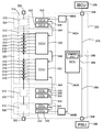
- a sub power storage system 202 illustrated in FIG. 2 illustrates a configuration of one of a plurality of sub power storage systems 202 provided in the power storage system 200 illustrated in FIG.
- the sub power storage system 202 can be considered as the power storage system 200.
- a large-scale power storage system can be created by connecting a large number of systems shown in FIG. 2 in parallel, or by connecting them in series and in parallel. Therefore, the power storage system 200 shown in FIG. 1 can be completed by combining the number of sub power storage systems 202 adapted to the needs with the configuration shown in FIG. 2 as a basic unit.
- the system shown in FIG. 2 is referred to as a sub power storage system for convenience.
- Each sub power storage system 202 shown in FIG. 2 further includes a plurality of battery blocks 212 serving as a basic configuration.
- each battery block 212 By sharing the basic structure and basic operation of each battery block 212, it is possible to set the storage capacity of the sub power storage system 202, which is the basic unit, to a capacity that is easy to use, thereby improving convenience.
- productivity and safety are improved.
- each sub power storage system 202 constituting the battery system 200 is disconnected from the other sub power storage system 202 to stop the operation, and maintenance and inspection can be performed, the battery system 200 continues to operate, Maintenance inspection of a specific sub power storage system 202 is possible.
- the specific sub power storage system 202 has the battery block 212 as a basic configuration, and a plurality of battery blocks 212 are connected to form the sub power storage system 202. Therefore, without stopping the operation of the sub power storage system 202, The specific battery block 212 can be disconnected from the other battery blocks 212, and the operation of the specific battery block 212 can be stopped for maintenance inspection.
- each battery block 212 The positive end portion 244 of each battery block 212 is connected in parallel to the positive side connection 246 via the disconnector 238, and similarly, the negative end portion 245 of each battery block 212 is respectively connected to the negative side connection 247 via the disconnector 239. Connected in parallel.
- the positive connection 246 to which the battery blocks 212 are connected in parallel is connected to the positive output terminal 248 via the circuit breaker 242, and the negative connection 247 is connected to the negative output terminal 249 via the disconnector 240.
- the circuit breaker 242 is controlled by a system controller (BSCU) 270.
- BSCU system controller
- the battery blocks 212 are connected in parallel to the positive output terminal 248 and the negative output terminal 249, and the positive output The end 248 and the negative output terminal 249 are connected in parallel with the other sub power storage system 202 as shown in FIG.
- the system controller (BSCU) 270 opens the circuit breaker 242 and the sub power storage system. The charging current or discharging current of the assembled battery 314 provided in 202 is cut off, and then the switches that are the disconnectors 238, 239, and 240 are opened.
- the switches which are the disconnectors 238, 239 and 240, are closed, and then the circuit breaker 242 is system controlled. Closed by device (BSCU) 270.
- the battery blocks 212 constituting the sub power storage system 202 are connected in parallel via a disconnector 238 and a disconnector 239 which are switches, and the sub power storage system 202 shown in FIG.
- the sub power storage system 202 shown in FIG. 2 is electrically connected to another sub power storage system 202 in a state where the battery block 212 in the state is opened. In this way, the sub power storage system 202 shown in FIG. 2 can be used as an operation state, and only the operation of the battery block 212 in which the specific disconnector 238 and the disconnector 239 are open can be stopped. Maintenance or inspection can be performed.
- Each battery block 212 has two sets of battery units 222 in parallel connection. Two sets of battery units 222 may be connected in series depending on the magnitude of the DC voltage to be stored. In this embodiment, in order to easily maintain safety in maintenance or inspection, two sets of battery units 222 are connected in parallel. As a result, the voltage in the battery block 212 is 1000 volts or less, particularly 650 volts or less. A relatively safe voltage is maintained.
- the DC voltage inside and output of the sub power storage system 202 which is a basic configuration for constructing the power storage system 200
- a relatively safe voltage not only maintenance or inspection of the power storage system 200 but also facility installation standards are relaxed. There is an effect that can be done.
- By connecting the battery units 222 in parallel a large amount of DC power can be stored, and this DC power can be converted to an optimum voltage, for example, boosted to a high voltage after being converted to AC power.
- the number of battery units 222 included in each battery block 212 is not limited to two sets, and can be determined according to the purpose and conditions of use of the power storage system 200. Considering convenience in maintenance or inspection, a more desirable effect can be obtained by setting the number of battery units 222 in parallel in this embodiment to two.
- Each battery block 212 has two sets of battery units 222 as described above, and each battery unit 222 further incorporates a plurality of battery packs 252. In this embodiment, each battery unit 222 incorporates three battery packs 252. As will be described below, each battery pack 252 further includes a plurality of battery groups 312. In this embodiment, each battery pack 252 includes four battery groups 312 as described later with reference to FIG. As will be described below, each battery group 312 further includes a plurality of cells 310. In this embodiment, each battery group 312 includes 12 cells 310 as will be described later.
- Each battery pack 252 has a battery control unit (BCU) 264 for managing and controlling the built-in battery group 312.
- Each battery control unit (BCU) 264 detects and diagnoses the terminal voltage of each cell 310 included in each battery group 312 of the built-in battery pack 252 and adjusts the state of charge. Further, the terminal voltage detection or diagnosis result or charging state of each cell 310 is reported from each battery control unit (BCU) 264, which is a host control unit, to the integrated control unit (IBCU) 226.
- Each battery control unit (BCU) 264 may directly detect and diagnose the terminal voltage of each cell 310 included in each related battery group 312 and directly adjust the state of charge. However, as shown in FIG.
- the battery control unit (BCU) 264 may cause the cell monitoring circuit (CCU) 332 to perform the above-described processing by giving a command to the 332.
- Each battery block 212 includes two sets of battery units 222A and 222B, and an integrated unit 224 is provided to control or manage the two sets of battery units 222A and 222B.
- the integrated unit 224 performs an electrical opening / closing operation of connecting or releasing each battery unit 222A or 222B with another battery block 212 and an integrated control unit (IBCU) 226 for performing management in the battery block 212.
- Relays 232, 233, 234, 235 to be performed, current detectors 228 and 229 for detecting the current flowing through each battery unit 222A or 222B, and a voltage detector for detecting the voltage between the terminals of each battery unit 222A or 222B 230 and 231 are provided.
- Each integrated control unit (IBCU) 226 manages all battery packs 252 built in the battery block 212 and controls whether or not the battery unit 222A or 222B is connected to another battery block 212 as a unit. By connecting the battery unit 222A or 222B to the relay 234 or 235, or both the relays 234 and 235, connecting to the other battery block 212, and closing the breaker 242 described above, The battery unit 222 having the relays 234 and 235 closed is electrically connected, and charging or discharging current is exchanged.
- the integrated control unit (IBCU) 226 receives information from each battery pack 252 or receives information and instructions from the system control unit (BSCU) 270, and further measures the charge / discharge current by the voltage detectors 230 and 231 and detects the voltage.
- the devices 230 and 231 measure the terminal voltage of the battery unit 222, and issue a command to each battery pack 252 based on these measured values and information and commands received from the system control unit (BSCU) 270. Further, the relays 232, 233, 234, and 235 are controlled.
- the integrated control unit (IBCU) 226 displays the operation state including the diagnosis result of the battery block 212, the measurement result by the current detectors 228 and 229 and the measurement result by the voltage detectors 230 and 231, as a system control unit (BSCU) 270. To report to.
- BSCU system control unit
- the relay 232 is first closed for connection through the current limiter 236.
- the current value flowing at this time can be measured by the current detector 228.
- the relay 234 is closed and the relay 232 is opened in a state where the charging or discharging current value of the battery unit 222A is not more than a predetermined value. By doing in this way, the charge / discharge current value of the cell 310 can be maintained at a safe value.
- a lithium battery is used as the cell 310.
- the terminal voltage of the lithium battery changes based on the SOC. Therefore, the current when the relay 234 is turned on can be predicted using the measured value of the voltage detector 230.
- the current flowing in the current limiter 236 is limited to a safe value by turning on the relay 232 in order to improve safety, and the relay 234 is turned on based on the measured value of the voltage detector 230. May be controlled.
- the relay 232 may be omitted and the relay 234 may be suddenly turned on.
- the control of the relay 233 and the relay 235 related to the battery unit 222B is the same as the content of the battery unit 222A described above.
- each sub power storage system 202 includes the integrated control device 226, and information and commands from the integrated control device 226 are transmitted to various devices connected via the information bus 272, and It is also transmitted to the system controller (BSCU) 270 of the system. Further, system control device 270 information and commands are sent from the management device (not shown) of the power storage system 200 shown in FIG.
- the system controller (BSCU) 270 is based on information and requests from the integrated controller 226 of each battery block 212, or on the basis of information and instructions from a management device (not shown) of the upper power storage system 200.
- the sub power storage system 202 is electrically disconnected from the system of the power storage system 200, and the current flowing through the negative output terminal 249 is interrupted.
- the disconnector 240 is opened.
- the disconnector 238 and the disconnector 239 that connect the battery blocks 212 in parallel are also disconnected.
- Such a circuit configuration facilitates maintenance and inspection in units of sub power storage systems 202. Furthermore, safety is improved. Further, by combining the battery blocks based on the required power storage scale with the battery block as a basic unit, a power storage system can be constructed, and productivity is improved. By increasing the combined safety, there is an effect of improving the safety of the entire power storage system. That is, it is possible to improve convenience that can meet demands and to improve safety.
- the system control unit (BSCU) 270 and each battery block 212 are managed, that is, the integrated control unit (IBCU) 226 that controls and diagnoses each battery block 212, the battery unit 222A, and the battery unit.
- the battery control unit (BCU) 264 included in the 222B includes a control circuit that is the center of the computer, and it is necessary to supply power for operation to these control circuits. Since the control circuit operates with a relatively low DC voltage, in the present embodiment, the stored voltage is not used, but an AC current that allows easy voltage conversion is used.
- each battery pack 212 or the sub power storage system 202 may be used as well as the electric power for operating the system control device 270 and the integrated control device 226. However, the maintenance check of each battery pack can be performed smoothly. From the viewpoint of performing and improving the productivity of the power storage system 200 by standardizing the configuration of each battery pack, in the embodiment shown in FIG. 2, a control device is provided from the outside of each battery pack 212 or the sub power storage system 202. It is configured to receive electric power for use. Also, by using AC power supplied from the outside, it is possible to easily convert the voltage using a transformer, and it is easier than converting the stored DC power to a low voltage with a DC / DC converter. Yes and efficient.
- AC power is supplied from the outside of the sub battery system 202 via the control power input terminal 282.
- the AC power from the control power input terminal 282 is supplied to the uninterruptible power supply 284, and normally a control DC voltage is generated by the AC power supplied via the control power input terminal 282.
- the uninterruptible power supply 284 replaces and supplies the necessary power.
- the uninterruptible power supply 284 can be composed of, for example, a secondary battery that stores DC power slightly higher than the voltage of the control power supply.
- the external AC power supplied via the control power supply input terminal 282 or the power supplied by the uninterruptible power supply 284 is supplied to the power supply unit 286, and a low DC voltage is generated by the power supply unit 286. It is supplied to the integrated control device 226 included in the device 270 and each battery block 212. Since the uninterruptible power supply 284 is provided, even if an abnormality occurs in which the AC power from the control power input terminal 282 is interrupted, the control power supplied from the power supply unit 286 does not stop.
- the sub power storage system 202 can continuously maintain the operation automatically and continuously from the use of AC power from the outside to the use of power supplied by the uninterruptible power supply 284.
- FIG. 3 shows a specific circuit configuration of the battery pack 252 described above.
- the battery pack 252 includes a battery control unit (BCU) 264 and a plurality of sets of modules 322 controlled by the battery control unit (BCU) 264.
- the battery pack 252 includes one battery control unit (BCU) 264 and four sets of modules 322 controlled by the battery control unit (BCU) 264.
- Each module 322 includes a plurality of cells 310 connected in series and a cell monitoring circuit (CCU) 332 that measures the state of the cells 310.
- CCU cell monitoring circuit
- each module 322 has twelve cells 310 connected in series and two monitoring circuits (CCU) 332 that measure the states of the twelve cells 310, and each monitoring circuit (CCU).
- Reference numeral 332 shares six cells 310 connected in series.
- the number of monitoring circuits (CCU) 332 may be three, and one monitoring circuit (CCU) 332 may manage four cells 310.
- a plurality of cells 310 (12 cells 310 in this embodiment) included in each module 322 are connected in series to form a battery group 312.
- the battery groups 312 of all the modules 322 included in the battery pack 252 are connected in series to form an assembled battery 314, and the assembled battery 314 is connected via the positive electrode power connector 352 and the negative electrode power connector 353 which are both terminals thereof.
- the battery pack 252 assembled battery is connected in series.
- the battery group 312 included in each module 322 is shared and managed by the cell monitoring circuit (CCU) 332 as described above.
- the twelve cells 310 are divided into six high potential sides and six low potential sides, and the cell monitoring circuit corresponds to each of the six high potential sides and the six low potential sides.
- (CCU) 332 is provided, and the terminal of the cell 310 is connected to the input terminal of the corresponding cell monitoring circuit (CCU) 332.
- the cell monitoring circuit (CCU) 332 detects the terminal voltage of each cell 310 connected to the input terminal, and detects the state of charge SOC of each cell 310 based on the detected terminal voltage of each cell 310. Further, overcharge and overdischarge are diagnosed based on the terminal voltage of each cell 310. Further, a difference with respect to the state of charge SOC with the other cells 310, that is, a variation in the state of charge SOC is obtained, and an abnormality is diagnosed from the magnitude of the variation. When the variation in the state of charge SOC between the cells 310 is large, it can be determined that there is a high possibility that the cell 310 having a small state of charge SOC has caused a slight short circuit. These detection results and diagnosis results are reported to the battery control unit (BCU) 264 via the first transmission line 342 and the second transmission line 344 for serial transmission, and held in the memory 266.
- BCU battery control unit
- the state of charge SOC is detected and diagnosed by the cell monitoring circuit (CCU) 332 based on the terminal voltage of each cell 310
- the first transmission line 342 for serially transmitting the terminal voltage of each cell 310 is described.
- the second transmission line 344 to the battery control unit (BCU) 264 and the battery control unit (BCU) 264 can perform the above diagnosis.
- the battery control unit (BCU) 264 can grasp the entire cells 310 of the battery pack 252 by reporting from each cell monitoring circuit (CCU) 332. For this reason, it is possible to grasp the variation in the state of charge SOC for all the cells 310 included in the battery pack 252 and more accurately diagnose a minute short circuit or the like.
- the serial transmission line includes two sets of insulation circuits 346A and 346B. These insulation circuits are connected at two locations of the first transmission line 342 and the second transmission line 344 and the first transmission line 342 and the second transmission line 344. Provided in each part.
- the battery control unit (BCU) 264 operates by receiving DC power supplied from the control power supply line 288 shown in FIG.
- each cell monitoring circuit (CCU) 332 receives DC power supplied from the series circuit of the monitored cell 310 and operates.
- the reference potential of the power supply voltage supplied to the battery control unit (BCU) 264 is different from the reference potential of the power supply voltage supplied to each cell monitoring circuit (CCU) 332. For this reason, the potential of the first transmission line 342 and the potential of the second transmission line 344 are different. Since it is not preferable to electrically connect the first transmission line 342 and the second transmission line 344, the first transmission line 342 and the second transmission line 344 are connected via the insulating circuit 346.
- each cell monitoring circuit (CCU) 332 also supplies power for operation from the cells 310 connected in series to the corresponding cell monitoring circuit (CCU) 332, the cell monitoring circuit (CCU) 332
- Each reference potential is different. That is, each cell monitoring circuit (CCU) 332 has a different reference potential of the cell 310 managed by the cell monitoring circuit (CCU) 332, and therefore the operating potential of each cell monitoring circuit (CCU) 332 is different.
- the reference potential is, for example, a ground potential of a circuit constituting each cell monitoring circuit (CCU) 332.
- the adjacent cell monitoring circuits (CCU) ) Since the input end and the output end of the transmission signal of the cell monitoring circuit (CCU) 332 are connected along the potential change of the cell monitoring circuit (CCU) 332, the adjacent cell monitoring circuits (CCU) ) The potential difference between 332 is small, and this potential difference is a value that the cell monitoring circuit (CCU) 332 can sufficiently withstand.
- the cell monitoring circuit (CCU) 332 is made of an integrated circuit formed of a semiconductor circuit, and the input terminal and the output terminal of the transmission signal of the cell monitoring circuit (CCU) 332 for configuring the second transmission line 344.
- the electronic circuit includes a circuit capable of withstanding a voltage larger than the potential difference between the adjacent cell monitoring circuits (CCU) 332, and the output terminal of the electrical cell monitoring circuit (CCU) 332 is connected to the next cell monitoring circuit (CCU). ) Even if it is electrically connected to the input terminal of 332, it operates normally. Therefore, as shown in FIG. 3, a series circuit for transmission of the cell monitoring circuit (CCU) 332 is formed along the potential change, so that the second circuit can be provided without providing an insulating circuit between the cell monitoring circuits (CCU) 332. A transmission line 344 can be formed.
- transmission is performed from the cell monitoring circuit (CCU) 332 having the higher potential in order toward the lower potential, but conversely, transmission may be performed from the lower potential to the higher potential.
- the output terminal of the cell monitoring circuit (CCU) 332 is electrically connected to the input terminal of the next cell monitoring circuit (CCU) 332, it may be connected via an electric resistance or a diode, or via a capacitor. May be connected.
- the insulating circuit 346 is specifically a photocoupler or a transformer, and once converts an electric signal into an optical signal or a magnetic flux signal as another transmission medium, and then converts it again into an electric signal for transmission.
- the first transmission line 342 and the second transmission line 344 can be reliably electrically insulated.
- a command from the battery control unit (BCU) 264 to each cell monitoring circuit (CCU) 332 is sent from the transmission transmission end of the battery control unit (BCU) 264 to the insulation circuit 346A via the first transmission line 342A, and the insulation circuit 346A is sent to the cell monitoring circuit (CCU) 332 on the high potential side via the second transmission line 344, and the cell transmission circuit (CCU) 332 is connected in series along the potential change, and the second transmission is configured.
- the command is transmitted to the insulation circuit 346B through the line 344, and returns to the transmission receiving end of the battery control unit (BCU) 264 through the first transmission line 342B.
- Each cell monitoring circuit (CCU) 332 confirms whether or not the address data in the transmission information having the sent command is itself, and if the address data corresponds to its own address, In response, the received information or the information requested based on the contents of the command is added, and the information is transmitted to the next cell monitoring circuit (CCU) 332 in the order of the transmission direction.
- Each cell monitoring circuit (CCU) 332 responds to a request from the battery control unit (BCU) 264 and transmits a detailed measurement result or diagnosis result to the battery control unit (BCU) 264 as transmission information.
- Each cell monitoring circuit (CCU) 332 can perform various diagnoses in addition to overcharge and overdischarge, and transmits these diagnosis results.
- FIG. 3 shows one set of transmission lines, but this is a representative example, and actually a plurality of sets of serial transmission lines are provided. One of them is used as an emergency transmission line.
- an abnormal signal may be sent to the battery control unit (BCU) 264. Is possible.
- the battery control unit (BCU) 264 is connected to an integrated control unit (IBCU) 226 that is a host control unit via an information bus 272 and an information bus connector 356.
- the measurement result and diagnosis result from the second transmission line 344 are reported to the integrated control unit (IBCU) 226 shown in FIG.
- the measurement result and the diagnosis result are held in the nonvolatile memory 266 included in the battery control unit (BCU) 264.
- the abnormality diagnosis result is held in the nonvolatile memory 266 together with the data specifying the abnormal cell 310 including the measurement result that is the basis of the abnormality diagnosis.
- Information reported from the battery control unit (BCU) 264 to the integrated control unit (IBCU) 226 is further reported to the system control unit (BSCU) 270 via the information bus 272.
- the battery pack 252 can be removed from the system as a unit, and the battery pack 252 can be replaced as necessary.
- the battery control unit (BCU) 264 has a nonvolatile memory 266, and the operation state or abnormal state of each cell 310 to be managed is held in the nonvolatile memory 266. Since the stored data can be read out with the battery pack 252 disconnected from the system, it is used for inspection and maintenance, replacement of the cell 310, or replacement in units of the module 322 as described above. it can.
- the integrated control unit (IBCU) 226 receives a report of the state of charge SOC of the cell 310 from each battery control unit (BCU) 264 and charges the cells 310 connected in series.
- the minimum charge state SOC of the battery groups 312 connected in series is detected, and the variation of the state of charge SOC is detected, and the SOC is detected in each cell monitoring circuit (CCU) 332.
- CCU cell monitoring circuit
- each cell monitoring circuit (CCU) 332 discharges the instructed cell 310 by a discharge circuit (not shown).
- a method other than operating the above discharge circuit may be used. For example, a method of selectively charging the cell 310 having a low state of charge SOC may be used.
- the DC power necessary for operating the battery control unit (BCU) 264 and the integrated control unit (IBCU) 226 of each battery block 212 is generated by the power supply unit 286 shown in FIG.
- the integrated control unit (IBCU) 226 is supplied via a control power line 288.
- the control power line 288 in the battery pack 252 is connected via an external control power line 288 connected to the power unit 286, the control power connector 358, and the control power connector 368.
- the battery control unit (BCU) 264 in the battery pack 252 is supplied with power from the control power line 288 in each battery pack 252.
- the uninterruptible power supply 284 temporarily supplies AC power to the power supply unit 286 when supply of AC power from the control power input terminal 282 stops.
- the direct-current power required to operate the battery control unit (BCU) 264 and the integrated control unit (IBCU) 226 of each battery block 212 is relatively low power and low voltage, so that alternating current with easy voltage conversion is available. It is desirable to use power.
- the uninterruptible power supply 284 is an AC generator, and can supply power in a short time in the event of an abnormality in which the supply of AC power from the control power input terminal 282 is stopped.
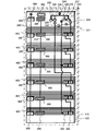
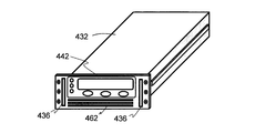
- FIG. 4 shows a battery block storage device 412 for storing each battery block 212.
- pack storage housings 432 for storing the battery packs 252 are provided.
- Each pack storage housing 432 has a drawer structure as shown in FIG. 8, and four modules 322 described in FIG. 3 are stored therein as shown in FIG.
- Each pack storage housing 432 can be easily removed by removing the screws on both sides shown in FIG. 8, and the battery pack 252 can be replaced by inserting another new pack storage housing 432 instead. .
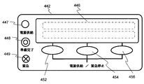
- An operation device 442 and an operation device 444 are provided in front of the integrated unit storage portion 422 and the pack storage housing 432, respectively.
- the operation device 442 and the operation device 444 have an operation unit and a display unit, and a representative example thereof is shown in FIG. 8, and an enlarged view thereof is shown in FIG. FIG. 10 shows the flow of air for cooling the inside of the pack housing housing 432.
- the three battery packs 252 constituting the battery unit 222A shown in FIG. 2 are housed in the lower three-stage pack housing housing 432, and the three battery packs 252 constituting the battery unit 222B shown in FIG. It is stored in a stage.
- the three battery packs 252 housed in the first to third stages from the bottom and the three battery packs 252 housed in the fourth to sixth stages from the bottom are provided at the back of the pack housing housing 432 shown in FIG. Are connected in series with each other.
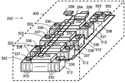
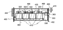
- FIG. 252 An outline of the battery pack 252 disposed inside the pack housing housing 432 is shown in FIG.
- the battery pack 252 has four modules 322 as shown in FIG. 3, and each module 322 has a battery group 312.
- Each module 322 has a battery group 312 composed of 12 cells 310 connected in series at the lower part thereof, and a positive terminal 336 and a negative terminal 337 are provided on both sides of the upper part.
- a cell monitoring circuit (CCU) 332 is disposed between the positive terminal 336 and the negative terminal 337 at the top of the module 322.
- the four modules 322 are arranged in a row in the direction from the front to the back of the pack housing housing 432.
- the battery groups 312 of the four modules 322 are connected in series by providing the conductor plate 338 in the front-to-back direction, and the four modules 322 connected in series. Are connected to the positive power connector 352 and the negative power connector 353.
- a transmission line connecting the cell monitoring circuit (CCU) 332 of each module 322 is connected to a battery control unit (BCU) 264, and an input / output terminal for transmission of the battery control unit (BCU) 264 is an integrated control unit (IBCU).
- IBCU integrated control unit
- 226 is connected to an information bus connector 356 for connection. Power for operation supplied from outside is taken in from a control power connector 358 and supplied to a battery control unit (BCU) 264.
- the wiring and connector shown in FIG. 7 are provided in the back of the storage device 412.
- the pack storage housing 432 is made of a case with a metal drawer structure shown in FIG. 8. By inserting the pack storage housing 432 shown in FIG. 8 from the storage port of the storage device 412, the pack storage housing 432 is inserted into the back of the pack storage housing 432.
- the positive power connector 352, the negative power connector 353, the information bus connector 356, and the control power connector 358 provided so as to protrude from the outer surface are the positive power connector 362 and the negative power connector 363 shown in FIG.
- the bus connector 366 and the control power connector 368 are connected to each other.
- three battery packs 252 provided in the first to third stages from the bottom are connected in series, and further three battery packs 252 provided in the fourth to sixth stages from the bottom are connected in series. Connected to.
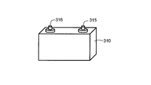
- the external shape of the cell 310 which comprises the battery group 312 is shown in FIG.
- the cell 310 is a lithium ion secondary battery having a square shape, but may be a lithium ion secondary battery having a cylindrical shape. Other secondary batteries may be used, but a lithium ion secondary battery is desirable because of the large amount of electricity stored in the volume.
- a positive electrode terminal 315 and a negative electrode terminal 316 are provided on the top of the cell 310, and a charging current is supplied from the positive electrode terminal 315 and the negative electrode terminal 316, and a discharge current can be taken out.
- FIG. 7 shows wiring and connectors provided in the back of the storage device 412, as well as measuring instruments and relays.
- the three battery packs 252 provided in the first to third stages from the bottom are connected in series, whereby the battery unit 222A is connected.
- the positive electrode side is connected to the relay 232 and the relay 234 provided on the uppermost stage, and is connected to the positive terminal 244 of the battery block 212 via the relay 232 and the relay 234.
- the negative side of the battery unit 222A is connected to the negative terminal 245.
- the integrated unit storage unit 422 is further provided with current detectors 228 and 229, which measure the charge / discharge current of the battery unit 222A and the charge / discharge current of the battery unit 222B. Further, the terminal voltages of the battery unit 222A and the battery unit 222B are measured by the voltage detector 230 and the voltage detector 231 described above. Further, an information bus connector 366 and a control power connector 368 are provided.
- the integrated unit storage unit 422 storing the integrated control unit (IBCU) 226 is inserted into the storage unit 412, whereby the input / output terminal of the integrated control unit (IBCU) 226 for information transmission of the integrated control unit (IBCU) 226.
- FIG. 8 shows an external shape of a pack storage housing 432 for storing the battery pack 252.
- the pack storage housing 432 is inserted into each stage of the storage device 412 shown in FIG.
- the integrated unit storage portion 422 has a shape and structure similar to those in FIG. However, the depth of the integrated unit storage portion 422 is made shorter than the depth of the pack storage housing 432, and the relay 232, the relay 233, and the relay are connected to the back of the integrated unit storage portion 422 together with the control power connector 368 and the information bus connector 366.
- a relay 235, a current limiter 236, a current limiter 237, and wiring are provided.
- an air introduction hole 462 for introducing air for cooling into the pack storage housing 432 is provided on the lower side, and an operation device 442 is provided on the upper side.
- handles 436 for carrying are provided on the left and right sides of the front side.
- a screw for fixing the pack storage housing 432 to the storage device 412 is provided after the pack storage housing 432 is stored on both the left and right sides of the front side.
- the display lamp 447, the display lamp 448, and the display lamp 449 represent the state of the battery pack 252 stored in the pack storage housing 432, and power for power supply is supplied to the battery control unit (BCU) 264. May be changed from the unlit state to the lit state, or the display color may be changed.
- the display lamp 448 is a display indicating that preparation for the next state is completed, and it can be detected from this display that preparation based on the operation is completed, and the next operation can be started.
- the display lamp 449 is a display indicating an abnormality, and a case where it is simply turned on and a flashing display indicating urgency may be used separately. The emergency state may be displayed by changing the color.
- the battery pack 252 stored in the pack storage housing 432 can be operated by the operation button 452, the operation button 454, and the operation button 456.
- the operation button 452, the operation button 454, and the operation button 456 are set.
- a switch not shown
- the operation command is operated by simultaneously operating the operation button 452, the operation button 454, and the operation button 456, whereby the operation command is transmitted to the battery control unit (BCU) 264.
- the battery unit 222 having the battery pack 252 transmitted and operated to the integrated control unit (IBCU) 226 is disconnected from the system operated by the integrated control unit (IBCU) 226.
- an emergency disconnection is transmitted from the integrated control unit (IBCU) 226 to the system control unit (BSCU) 270, and at the same time, the relay corresponding to the disconnection in the relay 235 is opened from the relay 232.
- the discharge current or the charge current flowing through the battery pack 252 in which an emergency abnormality has occurred can be interrupted.
- the occurrence of the emergency abnormality can be grasped by a diagnostic operation performed by the battery control unit (BCU) 264 or the cell monitoring circuit (CCU) 332. Further, it can be detected by the diagnostic operation of the integrated control unit (IBCU) 226 based on the output of the voltage detector 230 or 231 and the current detector 228 or 229 detected by the integrated control unit (IBCU) 226.
- Various displays associated with the driving are performed on the display unit 446 of the operation device 442. Further, by operating the operation button 452, the operation button 454, and the operation button 456, the terminal voltage of each cell 310, the internal temperature of the battery pack 252 and the state of the state of charge SOC can be displayed and checked. In addition, diagnosis history and past usage status can be displayed.
- the operation device 442 is provided for each battery pack 252, it is very useful to replace the battery pack 252 with another battery pack 252 for use. It is also very useful for maintenance management. It is possible to take out the pack storage housing 432 from the storage device 412 and supply power for operation from a separately prepared power source via the control power connector 358. In this case, the battery pack 252 is removed from various operations. Can be read out from the non-volatile memory 266 of the battery control unit (BCU) 264 that holds the use state and diagnostic contents, and can be displayed on the display unit 446.
- BCU battery control unit
- the stored contents of the integrated control unit (IBCU) 226 can be taken out from the information bus connector 356 of the removed battery pack 252 by the operation of the operation button 452, the operation button 454, and the operation button 456 as well as the display of the display unit 446. it can. This enables more accurate diagnosis or maintenance or inspection.
- each battery pack 252 is provided with an operating device 442, and the battery pack 252 is provided with a negative power connector 353 and a positive power connector 352, so that a positive power connector 352 and a negative power connector 353 are provided.
- the state SOC can be adjusted to the target value.
- the target value of the state of charge SOC is set by operating the operation button 452, the operation button 454, or the operation button 456, the target value of the state of charge SOC is sent from the information bus connector 356 to the SOC adjusting device, and the average charge of the battery pack 252 is performed.
- the current flowing through the positive electrode power connector 352 and the negative electrode power connector 353 is controlled by the SOC adjustment device so that the state SOC becomes the target value of the state of charge SOC.
- each cell monitoring circuit (CCU) 332 performs control to reduce the variation in the state of charge SOC so that the variation in the state of charge SOC of the cell 310 inside the battery pack 252 decreases.
- the display lamps 447 to 449 are very useful for such operations.
- FIG. 10 shows the flow of cooling air inside the battery pack 252.
- An air introduction hole 462 is provided in the lower front portion of the pack housing housing 432 shown in FIG. 8, and an air discharge hole 463 is provided in the back of the housing device 412 shown in FIG.
- the air discharge hole 463 is similarly provided in the uppermost stage, but the drawing of the air discharge hole 463 is omitted because the drawing becomes complicated.
- a fan 472 for introducing air is provided on the back surface. Cooling air is taken in from the air introduction hole 462 at the lower front surface by the fan 472 and flows through the first air passage 464 formed at the lower portion of the pack housing housing 432.
- a second air passage 466 is formed in the upper part of the pack storage housing 432.
- the first air passage 464 is provided with an air distributor 470 associated with the position of the module 322.
- the air distributor 470 is constituted by a weir that generates fluid resistance. By this 470, the air in the first air passage 464 moves through the inside of the module 322 to the second air passage 466. It is formed so that the fluid resistance of the weir as the air distributor 470 gradually increases so that the movement amount is balanced.
- each module 322 cools the cells 310 when passing between the cells 310 included in the battery group 312 of FIG.
- the air that has cooled the cell 310 is discharged from the air discharge hole 463 by the fan 472.
- the module 322 can be cooled with a compact structure.
- the impact on the module 322 can be reduced even if an external impact is applied during transportation such as removing the pack housing housing 432.
- it is extremely dangerous if the cell 310 is damaged there is an effect that the cell 310 can be prevented from being damaged by the deformation of the first or second air passages 464 and 466.
- the first air passage 464 is formed, so that there is no influence.
- FIG. 11 is an external view of a system block 502 that houses a portion related to the system management circuit in the sub power storage system 202 shown in FIG.
- the system block 502 includes a disconnecting unit storage unit 531 for storing a circuit breaker 242 and a plurality of 238s as a blocking unit from a lower stage, a control unit storage device 532 for storing a system control unit (BSCU) 270,
- the power supply unit storage device 533 for storing the power supply unit 286 and the uninterruptible power supply storage device 534 for storing the uninterruptible power supply device 284 are provided, and these storage devices are respectively stored in the housings 512 of the system block 502. Yes.
- a positive output terminal 248 and a negative output terminal 249 for connection to the system are provided on the rear surface of the housing 512, and these are connected to other subsystems shown in FIG.
- the system block 502 is provided with a control power input terminal 282 shown in FIG. 2 on the back surface, and the AC power supplied from the control power input terminal 282 is stored in the uninterruptible power storage device 534.
- the power is supplied to the power supply unit 286 stored in the power supply unit storage device 533 via the power supply device 284.
- the AC power supplied by the power supply unit 286 is converted into DC power and supplied to the system control device (BSCU) 270 stored in the control unit storage device 532, and a plurality of representative examples are shown in FIG.
- the battery blocks 212 are respectively supplied to the integrated control unit (IBCU) 226 and the battery control unit (BCU) 264 stored in the integrated unit storage unit 422 and the pack storage housing 432 of each battery block 212.
- DC power is supplied from the power supply unit 286 stored in the power supply unit storage device 533 in FIG. 11 to the control power supply line 288 shown in FIG. 7 and provided corresponding to each stage of the storage device 412. Is supplied to the control power connector 368 and supplied to the battery control unit (BCU) 264 and the cell monitoring circuit (CCU) 332 via the control power connector 358 shown in FIG.
- Each disconnector 238 is opened and closed by an operator's operation, while the breaker 242 is controlled and opened / closed by a system controller (BSCU) 270 housed in the controller housing 532.
- BSCU system controller
- an operation instruction is issued to the system control unit (BSCU) 270, and safety is confirmed by the system control unit (BSCU) 270 executing the instruction.
- Each storage device 531 to 534 of the system block 502 shown in FIG. 11 has operation devices 541 to 544 each having a display unit.
- the specific configurations of the operating devices 541 to 544 are basically the same as the operating device 442 shown in FIG.
- the operation state is displayed on the display part 446 shown in FIG. 9, and the display lamp 447 displays the operation in progress when the circuit breaker 242 is closed. Further, when the opening of the circuit breaker 242 is supported from the operation button 452 by the operation button 456, the safety is confirmed, and the display lamp 448 displays the completion of preparation. When the operation button 456 is operated again from the operation button 452 based on this display, the circuit breaker 242 is opened. When an emergency occurs and the circuit breaker 242 is opened, the display lamp 449 displays an emergency state.
- the power storage system 200 has a plurality of system blocks 502, it may be difficult to determine in a short time which actual system block 502 is involved even if an emergency operation is confirmed at the center. Being able to confirm with the display lamps 449 included in the operation devices 541 to 544 is useful for quick response.
- the uninterruptible power supply unit 284 included in the uninterruptible power supply storage unit 534 automatically operates when the supply of AC power from the outside is stopped. Also in this case, the display lamp 447 and the display lamp 449 operate when the uninterruptible power supply 284 is operating. Thereby, the emergency switch from the external AC power supply to the uninterruptible power supply 284 can be determined in a short time. Further, the emergency switching from the external AC power supply to the uninterruptible power supply 284 by the operator is performed by operating the operation buttons 452 and the operation buttons 456 shown in FIG.
- the display lamp 448 when the preparation for switching is completed based on the command, the display lamp 448 operates, and when the confirmation operation is further performed by the operation button 452 or the operation button 456, the display is switched to the uninterruptible power supply 284.
- the other operation devices 542 and 543 have the same basic configuration and basic operation.
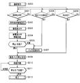
- FIG. 12 is a flowchart for explaining the operation of the battery block 212.
- step S100 may be started by inserting the pack storage housing 432 that stores the battery pack 252 constituting the battery block 212 into all the insertion portions of the storage device 412 shown in FIG. good.
- the pack storage housing 432 for storing the battery pack 252 is inserted into the storage device 412, the positive power connector 352 provided in the battery pack 252 shown in FIG. 5 and the connector 362 shown in FIG.
- the negative power connector 353 and the connector 363 are connected.
- the information bus connector 356 and the information bus connector 366 are connected, and the control power connector 358 and the control power connector 368 are connected.
- the power terminal of the IBCU 226 is connected to the control power connector 368, and the preparation for supplying the power for operation is completed. In this state, preparation for forming a transmission path for transmitting and receiving information is completed.
- step S102 it is confirmed whether or not power for operating the integrated control device (IBCU) 226 is supplied.
- the integrated control unit (IBCU) 226 does not start up until the operation in step S104 is performed.
- the display lamp 447 that displays the state of the operation device 444 provided in the integrated unit storage unit 422 is turned on.
- the control unit (IBCU) 226 starts up. The operating state moves from step S102 to step S106.
- step S104 when the PSU 286 enters an operating state by operating the operating device 543 of the power unit housing device 533 that is a power switch provided in the PSU 286 or by remote operation, the IBCU 226 of the battery block 212 and each battery pack 252 are Electric power is supplied to the battery control unit (BCU) 264. As a result, the IBCU 226 rises and automatically detects power supply. The condition of step S102 is satisfied, and the process proceeds to step S106 in the Yes direction.
- BCU battery control unit
- step S102 After the operation state is step S102, a display indicating that the IBCU 226 is ready for activation is displayed by the display lamp 448 provided on the operation device 444. After the operator confirms the display, as shown in step 105, the operator The activation of the IBCU 226 may be started by operating the operation button 456 from the IBCU power switch operation button 452 provided in the block 212.
- the operator After the operator sees the display of the start preparation completion of the IBCU 226, the operator starts the IBCU 226 by operating the IBCU power switch provided in the battery block. Then, the IBCU 226 performs a self-diagnosis as to whether or not there is any defect, and the activation of the IBCU 226 is completed. That is, it is possible to prevent the process from proceeding to step S106, which is the previous operation, until the activation of the IBCU 226 is completed. This method improves safety.
- step S106 the diagnosis result of each battery pack 252 is received from each battery control unit (BCU) 264.
- a diagnosis is made in step S106 as to whether or not the sum of the reported voltages of each battery control unit (BCU) 264 matches the sum of the measurement results of the voltage detector 230, that is, whether the difference is within a specified value.
- step S110 a command is issued to the cell monitoring circuit (CCU) 332 that has not yet reported the diagnosis result or voltage value. If there is an abnormality in the operation of the cell monitoring circuit (CCU) 332 itself or an abnormality in the communication path, the cell monitoring circuit (CCU) 332 cannot respond to the command. Diagnosis can also be made when there is an abnormality in its own operation or when there is an abnormality in the communication path.
- the integrated control unit (IBCU) 226 reports to the system control unit (BSCU) 270 regarding the completed battery unit 222A or battery unit 222B in step 112, 4 is displayed on the operation device 444 of FIG. 4 indicating that the battery unit 222 that has been safely connected is ready for connection.
- the system controller (BSCU) 270 is in a state of receiving an instruction to turn on the relay 232.
- the BSCU 270 When the BSCU 270 receives a completion report such as diagnosis from the IBCU 226, the BSCU 270 issues a connection permission to the battery unit 222 whose safety has been completed.
- the integrated control unit (IBCU) 226 receives a connection permission from the system control unit (BSCU) 270 in step S114, the relay 232 is turned on in step 116. In step 118, it is reported to each battery pack 252 that the relay 232 has been turned on, and the display unit 446 and the display lamp 447 of each battery pack 252 change to a display meaning that it is in operation.
- the cell monitoring circuit (CCU) 332 of each battery pack 252 measures the terminal voltage of each cell 310, and calculates the SOC based on the voltage reported from the battery control unit (BCU) 264.
- step S120 the variation of the SOC in the unit of the battery unit 222 is obtained, and when the variation is large, an instruction for equalization is given to each battery control unit (BCU) 264. Even if there is little variation in SOC with respect to the other battery units 222 in units of battery units 222, the variation between the battery packs 252 in the battery unit 222 is large, or the level of the battery group 312 in each battery pack 252. When the variation in SOC is large, an instruction for uniformizing the SOC is given to the battery control unit (BCU) 264.
- the battery pack 252 that has received the instruction displays the state of variation in the SOC on the display unit 446 and performs the operation of making the SOC uniform.
- the relay 232 When the relay 232 is turned on, the battery units 222 of the battery block 212 are connected in parallel with each other, and the operation of moving the stored power from the battery unit 222 having a large SOC to the battery unit 222 having a small SOC occurs. This produces an effect of uniforming the SOC. Therefore, not only the operation according to the instruction for uniformizing the SOC to the battery control unit (BCU) 264 but also the effect of uniformizing the SOC due to the effect of parallel connection is added, so that each battery unit 222 is gradually uniformized. . In this state, the relay 234 is turned on. By turning on the relay 234, almost no current flows through the relay 232, and the relay 232 is opened.
- the integrated control unit (IBCU) 226 sufficiently confirms the diagnosis result from each battery pack 252 and then turns on the relay 232, so that the battery block 212 is connected safely. Moreover, since the relay 232 provided with the current limiter 236 for preventing the abnormal current at the time of connection is turned on, and then the relay 234 constituting the circuit not having the current limiter 236 is turned on, sufficient safety is achieved. Can be secured.
- the battery pack 252 and the integrated unit 224 are reported to the driver by the display unit 446, the display lamp 447, the display lamp 448, and the display lamp 449 corresponding to the state of each battery pack 252 and the integrated unit 224, it is excellent in safety and convenience. Are better.
- step S200 starts.
- step S202 When the pack housing housing 432 having the battery pack 252 is inserted and the control power connector 358 is connected to the control power connector 368, when power is supplied to the control power connector 368, in steps S202 and S204, The display lamp 447 and the display lamp 448 shown in FIG. 9 are turned on.
- step S202 when the power supply unit 286 is in an operating state and power is supplied from the power supply unit 286 to the battery pack 252 via the control power supply connector 368, in step S202, a display indicating completion of power-on preparation is displayed. After confirming this display, the operator operates the operation buttons 452 to 456 provided on the operation device 442 in step S206. As a result, the battery control unit (BCU) 264 transitions to the activated state.
- BCU battery control unit
- the battery control unit (BCU) 264 When the battery control unit (BCU) 264 is activated, the battery control unit (BCU) 264 performs a self-diagnosis. If there is no abnormality in the self-diagnosis result, the activation of the BCU 264 in step S206 is completed.
- the cell monitoring circuit (CCU) 332 rises independently, and each performs detection of the terminal voltage of each responsible cell 310 and various diagnoses including overcharge and overdischarge.
- the detected terminal voltage of the cell 310 and the diagnosis result are reported from the cell monitoring circuit (CCU) 332 to the battery control unit (BCU) 264, and the battery control unit (BCU) 264 receives the report and stores it in the memory. .
- step S208 the battery control unit (BCU) 264 receives a report from the cell monitoring circuit (CCU) 332, determines whether there is an abnormality, and reports the result to the integrated control unit (IBCU) 226.
- step S106 of FIG. 12 described above the integrated control unit (IBCU) 226 receives this report from the battery control unit (BCU) 264.
- various modules in the battery pack 252 and the cell 310 are diagnosed, and when an abnormality occurs, or the cell 310 in which a specific measurement result appears with respect to another cell 310 and the module 322 including the cell 310 are operated.
- the information is displayed on the display unit 446 of the device 442.
- the cell 310 in which the decrease in the state of charge SOC is larger than the state of charge of the other cells 310 is likely to cause a slight short circuit. Therefore, displaying the cells 310 and the battery groups 312 having a large decrease in the state of charge SOC as compared with others on the display unit 446 of the operation device 442 is useful for maintenance inspection.
- step S209 the integrated control unit (IBCU) 226 reports to the related battery control unit (BCU) 264. Receiving the report, the battery control unit (BCU) 264 displays the contents on the display unit 446 of the operation device 442.
- the battery control unit (BCU) 264 receives the instruction in step S124 of FIG.
- An important content of this instruction is control for making the state of charge SOC of the assembled battery 314 uniform.
- the corresponding cell monitoring circuit (CCU) 332 is instructed to make the state of charge SOC uniform. Since the operation for equalizing the state of charge SOC normally takes a long time of about several hours, in step S212, for each cell 310 to which the cell monitoring circuit (CCU) 332 relates to the cell monitoring circuit (CCU) 332 concerned. Is set to the operation time for making the state of charge SOC uniform.
- step S212 the battery pack 252 transitions to a normal operation.
- the cell monitoring circuit (CCU) 332 that has received the instruction continues the operation for equalizing the state of charge SOC.
- FIG. 14 is an operation diagram in which a part of the battery control unit (BCU) 264, the integrated control unit (IBCU) 226, and the system control unit (BSCU) 270 that are linked is extracted from the contents described with reference to FIGS. Shown in In step S206, the battery control unit (BCU) 264 starts up, and in step S208, transmits the cell 310, the transmission path, and other necessary measurement results and diagnostic results of the related battery pack 252 to the integrated control unit (IBCU) 226. .
- the integrated control unit (IBCU) 226 starts up in step S102, and then receives a report from the battery control unit (BCU) 264 in step S106 and prepares to turn on the relay 232.
- the system control unit (BSCU) 270 is requested to permit the relay 232 to be turned on.
- step S112 upon receiving permission to turn on the relay 232 from the system control unit (BSCU) 270, the relay 232 is turned on, and the result is reported to the battery control unit (BCU) 264. That is, charging and discharging current flows through the battery pack 252 when the relay 232 is turned on.
- BSCU system control unit
- BCU battery control unit
- the battery control unit (BCU) 264 When the battery control unit (BCU) 264 receives a report on the input of the relay 232 from the integrated control unit (IBCU) 226 in step S209, the battery control unit (BCU) 264 indicates that the relay 232 is turned on and the battery unit 222 is connected to the system. The display is displayed on the display unit 446 of the battery pack 252.
- the integrated control unit (IBCU) 226 transmits an instruction for averaging the state of charge SOC to the corresponding battery control unit (BCU) 264 in step S124.
- the battery control unit (BCU) 264 receives this instruction in step S208, and sets an operation time for averaging the state of charge SOC in the cell monitoring circuit (CCU) 332 that manages the corresponding cell 310.
- the system controller (BSCU) 270 has been described on the assumption that the circuit breaker 242 has already been operated and the sub power storage system 202 is in operation.
- the system control unit (BSCU) 270 turns on the circuit breaker 242 and turns on the relay 232 in order from the battery unit 222 whose safety is confirmed.
- Step S300 is started from the state where the normal operation is performed.
- the IBCU 226 monitors the following three items. That is, (1) there is no abnormality in the cell 310 (step S301), (2) whether the operator desires to replace the battery pack 252 (step S308), (3) whether the operator desires to stop the battery block 212 (Step S309).
- step S301 Voltage value, current value, SOC state of each cell 310, temperature, transmission line connecting battery control unit (BCU) 264 and cell monitoring circuit (CCU) 332, battery control unit (BCU) 264 and integrated control unit ( IBCU) 226, transmission line connecting integrated control unit (IBCU) 226 and system control unit (BSCU) 270, operation of power supply unit 286 and uninterruptible power supply 284, cell monitoring circuit (CCU) 332 and integration
- the occurrence of an abnormality is monitored by the control unit (IBCU) 226 and the system control unit (BSCU) 270.
- Step S302 If there is an abnormality, for example, if the terminal voltage value of the cell 310 is greater than or equal to a predetermined value, if the short circuit occurs in the cell 310, or if an overcurrent flows in the cell 310, the contents are transmitted to the IBCU 226. (Step S302). At the same time, the BCU 264 displays on the display window 442 that there is an abnormality in the battery pack 252 including the cell 310. Further, the above contents are recorded in the nonvolatile memory 266 provided in the BCU 264.
- the battery control unit (BCU) 264 of the battery pack 252 reports the occurrence of the abnormality to the integrated control unit (IBCU) 226, and the IBCU 226 that has received this report in step S302 It is determined whether charging / discharging to the cell 310 should be stopped based on the received content. If the IBCU 226 determines that charging / discharging of the cell 310 should be stopped, in step S303, the associated relay among the relays 232 to 235 is opened, and the electrical connection of the relay is cut off.
- the disconnector 240 and the circuit breaker 242 are forcibly opened without going through steps S304 to S311 and the battery block 212 is opened. (Specifically, charging / discharging in the cell 310) is forcibly stopped.
- the IBCU 226 After the IBCU 226 confirms that the corresponding relay among the relays 232 to 235 is opened, the IBCU 226 transmits information of “relay opening complete” to the BSCU 270 (step S304). Thereby, BSCU 270 can grasp that the charging / discharging operation in battery block 212 is stopped.
- the IBCU 226 determines that charging / discharging should be stopped, the deterioration of the cell 310 caused by the abnormality or the degree of abnormality is diagnosed after the charging / discharging is stopped.
- a command to stop the operation of the battery pack 252 is transmitted to the BCU 264 (step S306).
- this may be the case when the state of charge SOC is very close to overdischarge or overcharge. In this case, it is a state which returns to normal by stopping an operation state.
- the IBCU 226 determines that the deterioration is severe or an abnormality such as an internal short circuit has occurred and self-repair is not possible ("replacement" direction in step S305)
- the IBCU 226 The display window 442 displays that the battery pack 252 needs to be replaced (pack replacement instruction) (step S307).
- the IBCU 226 waits for reception of information indicating that the operation of the battery pack 252 has been completed by the BCU 264 ("not received” in steps S310 and S311). direction).
- the IBCU 226 receives the operation stop completion information from the BCU 264 (in the “reception” direction in step S311), the IBCU 226 displays that the operation of the battery pack 252 has stopped on the display window 444, and the flow ends (step S312). ). Note that after the BCU 264 transmits the stop completion information in step S311, the power of the BCU 264 is turned off.
- step S308 (2) Request for replacement of battery pack 252 by the operator (step S308)
- step S300 normal operation
- the operator operates the battery pack replacement button provided on the battery pack 252 at an arbitrary timing.
- the battery pack 252 can be forcibly replaced (the “present” direction in step S308). In such a case, the process directly goes to step S307 without going through steps S302 to S305.
- step S309 Whether the operator wishes to stop the battery block 212 (step S309)
- step S300 normal operation
- the operator operates the battery block stop button provided on the battery pack 252 at an arbitrary timing.
- the operation of the battery block 212 can be forcibly stopped (the “present” direction in step S309). In such a case, the process proceeds to the above-described step S306 without going through the above-described steps S302 to S305.
- Lithium ion secondary batteries have advantages such as a long life because they have a large amount of electricity stored per volume and electrode deformation is not used during charging and discharging, but they require advanced control.
- the cell monitoring circuit (CCU) 332 is managed by the battery control unit (BCU) 264, further managed by the integrated control unit (IBCU) 226, and further managed by the system control unit (BSCU) 270. Therefore, detailed control is possible.
- the influence on the system using the power storage system is large.
- a part of the sub power storage system 202 can be stopped for inspection and repair.
- the battery block 212 is configured by combining necessary battery packs 252 having a common structure. Further, the sub power storage system 202 is configured by combining a necessary number of battery blocks 212 having a common structure according to the power storage capacity. In this way, it is possible to meet the needs, and high productivity and convenience can be obtained.
- step S105, step S204, step S206, etc. can be omitted. That is, for example, when step S105 is omitted, the integrated control unit (IBCU) 226 may be automatically started by supplying power.
- the operations from step S120 to step S124 may be performed before the execution of steps S112 to S118. That is, either the battery adjustment instruction from the battery unit 224 or the relay connection operation may be first.
Landscapes
- Engineering & Computer Science (AREA)
- Power Engineering (AREA)
- Charge And Discharge Circuits For Batteries Or The Like (AREA)
- Battery Mounting, Suspending (AREA)
- Secondary Cells (AREA)
Abstract
La présente invention vise à proposer un système de stockage d'électricité qui présente d'excellentes caractéristiques de sécurité. A cet effet, est proposé un système de stockage d'électricité qui comprend : une pluralité d'éléments destinés à stocker de l'électricité ; une pluralité d'ensembles accumulateurs (252), chacun comprenant des groupes d'accumulateurs (312), qui sont composés en montant en série la pluralité d'éléments, et un dispositif de commande d'accumulateur (264) qui commande les groupes d'accumulateurs (312) ; une pluralité de carters de stockage d'ensembles accumulateurs (432) qui abritent chacun l'ensemble accumulateur (252) et qui comprennent des connecteurs électriques d'ensemble accumulateur (362) afin de connecter les groupes d'accumulateurs (312) avec d'autres groupes ; un appareil récepteur (412) qui stocke les carters de stockage d'ensembles accumulateurs (432) et qui possède des connecteurs électriques d'appareil récepteur (362) afin qu'y soient connectés les connecteurs électriques d'ensemble accumulateur (362) des carters de stockage d'ensembles accumulateurs (432) ; des commutateurs (232) destinés à connecter les ensembles accumulateurs (252) entre eux et les ensembles accumulateurs (252) à un circuit extérieur ; et des dispositifs de commande intégrés (226) destinés à commander les commutateurs (232). Dans ce système de stockage d'électricité, chacun des dispositifs de commande intégrés (226) reçoit des informations des dispositifs de commande d'accumulateur (264) des ensembles accumulateurs (252) et commande l'ouverture et la fermeture des commutateurs (232).
Priority Applications (2)
| Application Number | Priority Date | Filing Date | Title |
|---|---|---|---|
| PCT/JP2011/054014 WO2012114479A1 (fr) | 2011-02-23 | 2011-02-23 | Système de stockage d'électricité pourvu d'accumulateurs |
| JP2013500771A JP5675951B2 (ja) | 2011-02-23 | 2011-02-23 | 電池を備えた蓄電システム |
Applications Claiming Priority (1)
| Application Number | Priority Date | Filing Date | Title |
|---|---|---|---|
| PCT/JP2011/054014 WO2012114479A1 (fr) | 2011-02-23 | 2011-02-23 | Système de stockage d'électricité pourvu d'accumulateurs |
Publications (1)
| Publication Number | Publication Date |
|---|---|
| WO2012114479A1 true WO2012114479A1 (fr) | 2012-08-30 |
Family
ID=46720298
Family Applications (1)
| Application Number | Title | Priority Date | Filing Date |
|---|---|---|---|
| PCT/JP2011/054014 Ceased WO2012114479A1 (fr) | 2011-02-23 | 2011-02-23 | Système de stockage d'électricité pourvu d'accumulateurs |
Country Status (2)
| Country | Link |
|---|---|
| JP (1) | JP5675951B2 (fr) |
| WO (1) | WO2012114479A1 (fr) |
Cited By (15)
| Publication number | Priority date | Publication date | Assignee | Title |
|---|---|---|---|---|
| JP2014147139A (ja) * | 2013-01-25 | 2014-08-14 | Keihin Corp | 蓄電池システム |
| JP2014147140A (ja) * | 2013-01-25 | 2014-08-14 | Keihin Corp | 蓄電池システム |
| JP2014147138A (ja) * | 2013-01-25 | 2014-08-14 | Keihin Corp | 蓄電池システム |
| JP2014147137A (ja) * | 2013-01-25 | 2014-08-14 | Keihin Corp | 蓄電池システム |
| JP2014193109A (ja) * | 2013-03-26 | 2014-10-06 | Lsis Co Ltd | バッテリ装置及びそれを含むエネルギー蓄積システム |
| JP2015006102A (ja) * | 2013-06-21 | 2015-01-08 | 株式会社東芝 | 蓄電池システム及び蓄電池システムの制御方法 |
| JP2015149226A (ja) * | 2014-02-07 | 2015-08-20 | 日立マクセル株式会社 | 蓄電装置 |
| KR20160012108A (ko) * | 2013-03-15 | 2016-02-02 | 디자인 플럭스 테크놀로지스, 엘엘씨 | 동적으로 재구성가능한 에너지 스토리지 장치를 생성하기 위한 방법 및 장치 |
| JP2016046887A (ja) * | 2014-08-21 | 2016-04-04 | ソニー株式会社 | 蓄電システム |
| WO2016147306A1 (fr) * | 2015-03-16 | 2016-09-22 | 株式会社東芝 | Appareil, procédé et programme de gestion de batterie de stockage |
| JP2017017821A (ja) * | 2015-06-30 | 2017-01-19 | 株式会社東芝 | 電池パックおよびその制御方法 |
| US9634500B2 (en) | 2013-01-25 | 2017-04-25 | Keihin Corporation | Storage battery system |
| KR20180081000A (ko) * | 2017-01-05 | 2018-07-13 | 삼성에스디아이 주식회사 | 차체 부품, 그 차체 부품과 통합되어 형성된 차량용 전지시스템 및 이를 포함하는 통합 전지시스템 차량 |
| JP2023051118A (ja) * | 2021-09-30 | 2023-04-11 | 積水化学工業株式会社 | 蓄電素子ユニットの設置方法 |
| US12351013B2 (en) | 2017-01-05 | 2025-07-08 | Samsung Sdi Co., Ltd. | Chassis components, vehicle battery system integrally formed with chassis components, and integrated battery system vehicle comprising same |
Citations (3)
| Publication number | Priority date | Publication date | Assignee | Title |
|---|---|---|---|---|
| JP2000156934A (ja) * | 1998-11-19 | 2000-06-06 | Nissin Electric Co Ltd | 電力貯蔵システム及びその充電方法 |
| JP2003289629A (ja) * | 2002-03-27 | 2003-10-10 | Mitsubishi Heavy Ind Ltd | 蓄電装置の電圧均等化装置及び該装置を備えた電力貯蔵システム |
| JP2005176461A (ja) * | 2003-12-09 | 2005-06-30 | Matsushita Electric Ind Co Ltd | 直流無停電電源装置 |
Family Cites Families (1)
| Publication number | Priority date | Publication date | Assignee | Title |
|---|---|---|---|---|
| KR100948003B1 (ko) * | 2006-02-27 | 2010-03-18 | 주식회사 엘지화학 | 우수한 냉각 효율성의 중대형 전지팩 |
-
2011
- 2011-02-23 WO PCT/JP2011/054014 patent/WO2012114479A1/fr not_active Ceased
- 2011-02-23 JP JP2013500771A patent/JP5675951B2/ja not_active Expired - Fee Related
Patent Citations (3)
| Publication number | Priority date | Publication date | Assignee | Title |
|---|---|---|---|---|
| JP2000156934A (ja) * | 1998-11-19 | 2000-06-06 | Nissin Electric Co Ltd | 電力貯蔵システム及びその充電方法 |
| JP2003289629A (ja) * | 2002-03-27 | 2003-10-10 | Mitsubishi Heavy Ind Ltd | 蓄電装置の電圧均等化装置及び該装置を備えた電力貯蔵システム |
| JP2005176461A (ja) * | 2003-12-09 | 2005-06-30 | Matsushita Electric Ind Co Ltd | 直流無停電電源装置 |
Cited By (28)
| Publication number | Priority date | Publication date | Assignee | Title |
|---|---|---|---|---|
| US9634500B2 (en) | 2013-01-25 | 2017-04-25 | Keihin Corporation | Storage battery system |
| JP2014147140A (ja) * | 2013-01-25 | 2014-08-14 | Keihin Corp | 蓄電池システム |
| JP2014147138A (ja) * | 2013-01-25 | 2014-08-14 | Keihin Corp | 蓄電池システム |
| JP2014147137A (ja) * | 2013-01-25 | 2014-08-14 | Keihin Corp | 蓄電池システム |
| JP2014147139A (ja) * | 2013-01-25 | 2014-08-14 | Keihin Corp | 蓄電池システム |
| JP2016517258A (ja) * | 2013-03-15 | 2016-06-09 | デザイン フラックス テクノロジーズ, エルエルシーDesign Flux Technologies, Llc | 動的に再構成可能なエネルギー貯蔵装置を作り出す方法および装置 |
| KR20160012108A (ko) * | 2013-03-15 | 2016-02-02 | 디자인 플럭스 테크놀로지스, 엘엘씨 | 동적으로 재구성가능한 에너지 스토리지 장치를 생성하기 위한 방법 및 장치 |
| KR102201102B1 (ko) * | 2013-03-15 | 2021-01-12 | 디자인 플럭스 테크놀로지스, 엘엘씨 | 동적으로 재구성가능한 에너지 스토리지 장치를 생성하기 위한 방법 및 장치 |
| JP2019110750A (ja) * | 2013-03-15 | 2019-07-04 | ジーエルエックス、パワー、システムズ、インコーポレイテッドGlx Power Systems Inc. | 動的に再構成可能なエネルギー貯蔵装置を作り出す方法および装置 |
| JP2014193109A (ja) * | 2013-03-26 | 2014-10-06 | Lsis Co Ltd | バッテリ装置及びそれを含むエネルギー蓄積システム |
| US9653921B2 (en) | 2013-03-26 | 2017-05-16 | Lsis Co., Ltd. | Battery device and energy storage system including the same |
| JP2015006102A (ja) * | 2013-06-21 | 2015-01-08 | 株式会社東芝 | 蓄電池システム及び蓄電池システムの制御方法 |
| JP2015149226A (ja) * | 2014-02-07 | 2015-08-20 | 日立マクセル株式会社 | 蓄電装置 |
| US10389142B2 (en) | 2014-08-21 | 2019-08-20 | Murata Manufacturing Co., Ltd. | Electric storage system |
| JP2016046887A (ja) * | 2014-08-21 | 2016-04-04 | ソニー株式会社 | 蓄電システム |
| US9859721B2 (en) | 2015-03-16 | 2018-01-02 | Kabushiki Kaisha Toshiba | Storage battery management device, method, and computer program product |
| CN107431363A (zh) * | 2015-03-16 | 2017-12-01 | 株式会社东芝 | 蓄电池管理装置、方法以及程序 |
| JPWO2016147306A1 (ja) * | 2015-03-16 | 2017-04-27 | 株式会社東芝 | 蓄電池管理装置、方法及びプログラム |
| WO2016147306A1 (fr) * | 2015-03-16 | 2016-09-22 | 株式会社東芝 | Appareil, procédé et programme de gestion de batterie de stockage |
| CN107431363B (zh) * | 2015-03-16 | 2020-06-26 | 株式会社东芝 | 蓄电池管理装置及蓄电池管理方法 |
| EP3093947A4 (fr) * | 2015-03-16 | 2017-03-01 | Kabushiki Kaisha Toshiba | Appareil, procédé et programme de gestion de batterie de stockage |
| US9887572B2 (en) | 2015-06-30 | 2018-02-06 | Kabushiki Kaisha Toshiba | Battery pack and control method for controlling output of battery pack for connecting external load |
| JP2017017821A (ja) * | 2015-06-30 | 2017-01-19 | 株式会社東芝 | 電池パックおよびその制御方法 |
| KR20180081000A (ko) * | 2017-01-05 | 2018-07-13 | 삼성에스디아이 주식회사 | 차체 부품, 그 차체 부품과 통합되어 형성된 차량용 전지시스템 및 이를 포함하는 통합 전지시스템 차량 |
| KR102608242B1 (ko) * | 2017-01-05 | 2023-11-29 | 삼성에스디아이 주식회사 | 차체 부품, 그 차체 부품과 통합되어 형성된 차량용 전지시스템 및 이를 포함하는 통합 전지시스템 차량 |
| US12351013B2 (en) | 2017-01-05 | 2025-07-08 | Samsung Sdi Co., Ltd. | Chassis components, vehicle battery system integrally formed with chassis components, and integrated battery system vehicle comprising same |
| JP2023051118A (ja) * | 2021-09-30 | 2023-04-11 | 積水化学工業株式会社 | 蓄電素子ユニットの設置方法 |
| JP7784263B2 (ja) | 2021-09-30 | 2025-12-11 | 積水化学工業株式会社 | 蓄電素子ユニットの設置方法 |
Also Published As
| Publication number | Publication date |
|---|---|
| JP5675951B2 (ja) | 2015-02-25 |
| JPWO2012114479A1 (ja) | 2014-07-07 |
Similar Documents
| Publication | Publication Date | Title |
|---|---|---|
| JP5675951B2 (ja) | 電池を備えた蓄電システム | |
| EP2693514B1 (fr) | Dispositif électrique à bâti et bloc batterie comportant un connecteur séparable | |
| US10263436B2 (en) | Electrical energy storage unit and control system and applications thereof | |
| KR101856663B1 (ko) | 다중팩 병렬 구조의 정보 교환을 위한 2차 전지 관리 시스템 및 방법 | |
| JP5611727B2 (ja) | 電源装置 | |
| US9331497B2 (en) | Electrical energy storage unit and control system and applications thereof | |
| EP2658027A1 (fr) | Système d'alimentation électrique | |
| EP2940827B1 (fr) | Dispositif d'alimentation électrique utilisant un véhicule électrique | |
| US9929594B2 (en) | Modular energy storage method and system | |
| WO2011096430A1 (fr) | Dispositif d'alimentation électrique | |
| KR20190089421A (ko) | 배터리 관리 시스템,및 배터리 관리 시스템의 배터리모듈의 밸런싱 방법 | |
| EP2782201B1 (fr) | Unité de batterie rechargeable | |
| EP4173070A1 (fr) | Système accumulateur d'énergie utilisant des batteries en seconde vie | |
| EP3014726B1 (fr) | Systeme electrique accumulateur d'energie | |
| US20220077764A1 (en) | Electric energy conversion and control device and energy storage system having the same | |
| JP5553622B2 (ja) | 二次電池システムおよびその管理方法 | |
| CN119133659B (zh) | 船用储能系统及其放电方法 | |
| WO2012132769A1 (fr) | Système de protection de batterie | |
| KR20240019747A (ko) | 배터리 충전 관리 시스템 및 이를 이용한 충전 제어방법 | |
| CN119032485A (zh) | 使用二次寿命电动车辆电池的能量存储系统和方法 | |
| US20050007071A1 (en) | Circuit arrangement for an autonomous power supply system, and a method for its operation | |
| CN118174397A (zh) | 一种储能系统及其电池簇的充放电控制方法、装置 | |
| CN223040309U (zh) | 储能系统控制盒和储能系统 | |
| JP2020018095A (ja) | 電源システム及び電力の系統連系システム | |
| KR20260033134A (ko) | 전력 공급 유닛을 포함하는 배터리 시스템 및 이의 운영 방법 |
Legal Events
| Date | Code | Title | Description |
|---|---|---|---|
| 121 | Ep: the epo has been informed by wipo that ep was designated in this application |
Ref document number: 11859383 Country of ref document: EP Kind code of ref document: A1 |
|
| ENP | Entry into the national phase |
Ref document number: 2013500771 Country of ref document: JP Kind code of ref document: A |
|
| NENP | Non-entry into the national phase |
Ref country code: DE |
|
| 122 | Ep: pct application non-entry in european phase |
Ref document number: 11859383 Country of ref document: EP Kind code of ref document: A1 |