WO2012114482A1 - Système de commande de moteur à combustion interne - Google Patents
Système de commande de moteur à combustion interne Download PDFInfo
- Publication number
- WO2012114482A1 WO2012114482A1 PCT/JP2011/054031 JP2011054031W WO2012114482A1 WO 2012114482 A1 WO2012114482 A1 WO 2012114482A1 JP 2011054031 W JP2011054031 W JP 2011054031W WO 2012114482 A1 WO2012114482 A1 WO 2012114482A1
- Authority
- WO
- WIPO (PCT)
- Prior art keywords
- internal combustion
- combustion engine
- clearance
- compression
- fuel
- Prior art date
- Legal status (The legal status is an assumption and is not a legal conclusion. Google has not performed a legal analysis and makes no representation as to the accuracy of the status listed.)
- Ceased
Links
Images



Classifications
-
- F—MECHANICAL ENGINEERING; LIGHTING; HEATING; WEAPONS; BLASTING
- F02—COMBUSTION ENGINES; HOT-GAS OR COMBUSTION-PRODUCT ENGINE PLANTS
- F02D—CONTROLLING COMBUSTION ENGINES
- F02D15/00—Varying compression ratio
- F02D15/04—Varying compression ratio by alteration of volume of compression space without changing piston stroke
-
- F—MECHANICAL ENGINEERING; LIGHTING; HEATING; WEAPONS; BLASTING
- F02—COMBUSTION ENGINES; HOT-GAS OR COMBUSTION-PRODUCT ENGINE PLANTS
- F02B—INTERNAL-COMBUSTION PISTON ENGINES; COMBUSTION ENGINES IN GENERAL
- F02B75/00—Other engines
- F02B75/04—Engines with variable distances between pistons at top dead-centre positions and cylinder heads
- F02B75/041—Engines with variable distances between pistons at top dead-centre positions and cylinder heads by means of cylinder or cylinderhead positioning
-
- F—MECHANICAL ENGINEERING; LIGHTING; HEATING; WEAPONS; BLASTING
- F02—COMBUSTION ENGINES; HOT-GAS OR COMBUSTION-PRODUCT ENGINE PLANTS
- F02D—CONTROLLING COMBUSTION ENGINES
- F02D13/00—Controlling the engine output power by varying inlet or exhaust valve operating characteristics, e.g. timing
- F02D13/02—Controlling the engine output power by varying inlet or exhaust valve operating characteristics, e.g. timing during engine operation
- F02D13/0223—Variable control of the intake valves only
-
- F—MECHANICAL ENGINEERING; LIGHTING; HEATING; WEAPONS; BLASTING
- F02—COMBUSTION ENGINES; HOT-GAS OR COMBUSTION-PRODUCT ENGINE PLANTS
- F02D—CONTROLLING COMBUSTION ENGINES
- F02D41/00—Electrical control of supply of combustible mixture or its constituents
- F02D41/0025—Controlling engines characterised by use of non-liquid fuels, pluralities of fuels, or non-fuel substances added to the combustible mixtures
-
- F—MECHANICAL ENGINEERING; LIGHTING; HEATING; WEAPONS; BLASTING
- F02—COMBUSTION ENGINES; HOT-GAS OR COMBUSTION-PRODUCT ENGINE PLANTS
- F02D—CONTROLLING COMBUSTION ENGINES
- F02D45/00—Electrical control not provided for in groups F02D41/00 - F02D43/00
-
- F—MECHANICAL ENGINEERING; LIGHTING; HEATING; WEAPONS; BLASTING
- F02—COMBUSTION ENGINES; HOT-GAS OR COMBUSTION-PRODUCT ENGINE PLANTS
- F02D—CONTROLLING COMBUSTION ENGINES
- F02D19/00—Controlling engines characterised by their use of non-liquid fuels, pluralities of fuels, or non-fuel substances added to the combustible mixtures
- F02D19/06—Controlling engines characterised by their use of non-liquid fuels, pluralities of fuels, or non-fuel substances added to the combustible mixtures peculiar to engines working with pluralities of fuels, e.g. alternatively with light and heavy fuel oil, other than engines indifferent to the fuel consumed
- F02D19/0639—Controlling engines characterised by their use of non-liquid fuels, pluralities of fuels, or non-fuel substances added to the combustible mixtures peculiar to engines working with pluralities of fuels, e.g. alternatively with light and heavy fuel oil, other than engines indifferent to the fuel consumed characterised by the type of fuels
- F02D19/0642—Controlling engines characterised by their use of non-liquid fuels, pluralities of fuels, or non-fuel substances added to the combustible mixtures peculiar to engines working with pluralities of fuels, e.g. alternatively with light and heavy fuel oil, other than engines indifferent to the fuel consumed characterised by the type of fuels at least one fuel being gaseous, the other fuels being gaseous or liquid at standard conditions
-
- F—MECHANICAL ENGINEERING; LIGHTING; HEATING; WEAPONS; BLASTING
- F02—COMBUSTION ENGINES; HOT-GAS OR COMBUSTION-PRODUCT ENGINE PLANTS
- F02D—CONTROLLING COMBUSTION ENGINES
- F02D19/00—Controlling engines characterised by their use of non-liquid fuels, pluralities of fuels, or non-fuel substances added to the combustible mixtures
- F02D19/06—Controlling engines characterised by their use of non-liquid fuels, pluralities of fuels, or non-fuel substances added to the combustible mixtures peculiar to engines working with pluralities of fuels, e.g. alternatively with light and heavy fuel oil, other than engines indifferent to the fuel consumed
- F02D19/0663—Details on the fuel supply system, e.g. tanks, valves, pipes, pumps, rails, injectors or mixers
- F02D19/0686—Injectors
- F02D19/0689—Injectors for in-cylinder direct injection
-
- F—MECHANICAL ENGINEERING; LIGHTING; HEATING; WEAPONS; BLASTING
- F02—COMBUSTION ENGINES; HOT-GAS OR COMBUSTION-PRODUCT ENGINE PLANTS
- F02D—CONTROLLING COMBUSTION ENGINES
- F02D19/00—Controlling engines characterised by their use of non-liquid fuels, pluralities of fuels, or non-fuel substances added to the combustible mixtures
- F02D19/06—Controlling engines characterised by their use of non-liquid fuels, pluralities of fuels, or non-fuel substances added to the combustible mixtures peculiar to engines working with pluralities of fuels, e.g. alternatively with light and heavy fuel oil, other than engines indifferent to the fuel consumed
- F02D19/0663—Details on the fuel supply system, e.g. tanks, valves, pipes, pumps, rails, injectors or mixers
- F02D19/0686—Injectors
- F02D19/0692—Arrangement of multiple injectors per combustion chamber
-
- Y—GENERAL TAGGING OF NEW TECHNOLOGICAL DEVELOPMENTS; GENERAL TAGGING OF CROSS-SECTIONAL TECHNOLOGIES SPANNING OVER SEVERAL SECTIONS OF THE IPC; TECHNICAL SUBJECTS COVERED BY FORMER USPC CROSS-REFERENCE ART COLLECTIONS [XRACs] AND DIGESTS
- Y02—TECHNOLOGIES OR APPLICATIONS FOR MITIGATION OR ADAPTATION AGAINST CLIMATE CHANGE
- Y02T—CLIMATE CHANGE MITIGATION TECHNOLOGIES RELATED TO TRANSPORTATION
- Y02T10/00—Road transport of goods or passengers
- Y02T10/10—Internal combustion engine [ICE] based vehicles
- Y02T10/12—Improving ICE efficiencies
-
- Y—GENERAL TAGGING OF NEW TECHNOLOGICAL DEVELOPMENTS; GENERAL TAGGING OF CROSS-SECTIONAL TECHNOLOGIES SPANNING OVER SEVERAL SECTIONS OF THE IPC; TECHNICAL SUBJECTS COVERED BY FORMER USPC CROSS-REFERENCE ART COLLECTIONS [XRACs] AND DIGESTS
- Y02—TECHNOLOGIES OR APPLICATIONS FOR MITIGATION OR ADAPTATION AGAINST CLIMATE CHANGE
- Y02T—CLIMATE CHANGE MITIGATION TECHNOLOGIES RELATED TO TRANSPORTATION
- Y02T10/00—Road transport of goods or passengers
- Y02T10/10—Internal combustion engine [ICE] based vehicles
- Y02T10/30—Use of alternative fuels, e.g. biofuels
Definitions
- the present invention relates to a control system for an internal combustion engine.
- Patent Document 1 discloses an output of a dual fuel engine having a primary fuel system that supplies a mixture of air and gaseous fuel and a secondary fuel system that includes a fuel injection device that injects liquid fuel into a cylinder.
- a technique for changing the supply ratio of the primary fuel and the secondary fuel based on the output of the dual fuel engine is disclosed.
- Patent Document 2 in an engine, an air-fuel mixture including a first fuel having a higher self-ignitability than gasoline and a second fuel having a combustion speed faster than gasoline is formed in a combustion chamber and ignited.
- a technique is disclosed in which the supply ratio of the first fuel and the second fuel is adjusted so that the air-fuel mixture undergoes self-ignition combustion after flame propagation combustion.
- Patent Document 2 describes that in the engine, as the engine load decreases, the mechanical compression ratio of the engine is increased by the variable compression ratio mechanism.
- the extinguishing distance is the minimum distance through which a flame can propagate.
- the present invention has been made in view of the above problems, and an object thereof is to suppress the occurrence of misfire in an internal combustion engine.
- the clearance between the top surface of the piston and the cylinder head at the compression top dead center is changed according to the extinction distance when the fuel is ignited in the combustion chamber.
- control system for an internal combustion engine is: A clearance control unit that variably controls the clearance between the top surface of the piston and the cylinder head at the compression top dead center, When the flame extinguishing distance when the fuel is ignited is large, the clearance between the top surface of the piston and the cylinder head at the compression top dead center is increased by the clear lath control unit as compared to when the extinguishing distance is small.
- the extinguishing distance When the operating state of the internal combustion engine is in the low-load low-rotation region, the extinguishing distance is larger than when the internal combustion engine is in the high-load region or at least one of the high-rotation regions. Further, in a multi-fuel internal combustion engine that can be operated by mixing and burning a plurality of types of fuel, the extinguishing distance also changes when the properties of the fuel supplied to the internal combustion engine change. For example, in a multi-fuel internal combustion engine that uses liquid fuel and gas fuel as fuel, when the ratio of gas fuel in the whole fuel supplied to the internal combustion engine is high, the flame extinguishing is less than when the ratio of gas fuel is low. The distance is great.
- the control system for an internal combustion engine may further include a compression end temperature control unit.
- the compression end temperature control unit controls the compression end temperature by a method other than the method of changing the clearance between the top surface of the piston and the cylinder head at the compression top dead center.
- the internal combustion engine control system further includes a compression end temperature control unit, when the clearance control unit increases the clearance between the top surface of the piston and the cylinder head at the compression top dead center, the compression end temperature control unit The compression end temperature may be controlled to a temperature equal to or higher than that before the clearance is changed.
- the compression end temperature decreases. As a result, the amount of unburned fuel components may increase.
- the compression end temperature can be controlled by a method other than the method of changing the clearance between the top surface of the piston and the cylinder head at the compression top dead center.
- the clearance control unit suppresses a decrease in the compression end temperature when the clearance between the top surface of the piston and the cylinder head at the compression top dead center is increased. can do. Thereby, it becomes possible to suppress the increase in the amount of unburned fuel components.
- the occurrence of misfire in the internal combustion engine can be suppressed.
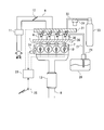
- FIG. 1 is a diagram illustrating a schematic configuration of an internal combustion engine and an intake / exhaust system thereof according to Embodiment 1.
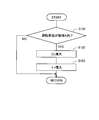
- FIG. It is a flowchart which shows the flow of misfire suppression control and compression end temperature rise control which concern on Example 1.
- FIG. It is a 1st map which shows the driving
- FIG. FIG. 6 is a second map showing an operation region in which misfire suppression control and compression end temperature rise control are executed according to the first embodiment.
- It is a figure which shows schematic structure of the internal combustion engine which concerns on Example 2, its intake-exhaust system, and a fuel system. It is a flowchart which shows the flow of misfire suppression control and compression end temperature rise control which concern on the modification of Example 2.
- FIG. 1 is a diagram showing a schematic configuration of an internal combustion engine and its intake / exhaust system according to the present embodiment.
- the internal combustion engine 1 is a diesel engine for driving a vehicle having four cylinders 2 and using light oil as fuel.
- a piston 3 is slidably provided in the cylinder 2.
- An intake port 4 and an exhaust port 5 are connected to the combustion chamber in the upper part of the cylinder 2.
- the openings of the intake port 4 and the exhaust port 5 to the combustion chamber are opened and closed by an intake valve 6 and an exhaust valve 7, respectively.
- the internal combustion engine 1 is provided with a fuel injector 10.
- the fuel injector 10 directly injects fuel (light oil) into the cylinder 2.
- An intake passage 8 is connected to the intake port 4.
- An exhaust passage 9 is connected to the exhaust port 5.
- An air flow meter 11 and a throttle valve 12 are provided in the intake passage 8.
- the air flow meter 11 detects the intake air amount of the internal combustion engine 1.
- the throttle valve 12 controls the intake air amount of the internal combustion engine 1 by changing the cross-sectional area of the intake passage in the direction perpendicular to the intake air flow direction.
- the exhaust passage 9 is provided with an exhaust purification device 13 constituted by an oxidation catalyst, a particulate filter or the like.
- the internal combustion engine 1 is provided with an intake side variable valve mechanism (hereinafter referred to as intake side VVT) 16.
- the intake side VVT 16 is a mechanism capable of variably controlling the valve timing of the intake valve 6.
- the internal combustion engine 1 is provided with a variable compression ratio mechanism 15.
- the variable compression ratio mechanism 15 is a mechanism capable of moving the cylinder block 22 in the vertical direction (the axial direction of the cylinder 2) with respect to the crankcase 23.
- the cylinder block 22 moves in the vertical direction with respect to the crankcase 23 (the cylinder head 21 also moves in the vertical direction integrally with the cylinder block 22)
- the top surface of the piston 3 at the compression top dead center changes.
- the combustion chamber volume changes, and as a result, the mechanical compression ratio changes.
- variable compression ratio mechanism 15 the clearance between the top surface of the piston 3 and the cylinder head 21 at the compression top dead center is obtained by moving the cylinder block 22 in the vertical direction with respect to the crankcase 23. Any known mechanism may be adopted as long as it changes the above.
- An electronic control unit (ECU) 20 is provided in the internal combustion engine 1 configured as described above.
- An air flow meter 11, a crank angle sensor 24, and an accelerator opening sensor 25 are electrically connected to the ECU 20. These output signals are input to the ECU 20.
- the crank angle sensor 24 is a sensor that detects the crank angle of the internal combustion engine 1.
- the ECU 20 derives the engine speed of the internal combustion engine 1 based on the output value of the crank angle sensor 24.
- the accelerator opening sensor 25 is a sensor that detects the accelerator opening of a vehicle on which the internal combustion engine 1 is mounted.
- the ECU 20 derives the engine load of the internal combustion engine 1 based on the output value of the accelerator opening sensor 25.
- the ECU 20 is electrically connected to the fuel injector 10, the throttle valve 12, the intake side VVT 16, and the variable compression ratio mechanism 15. These are controlled by the ECU 20.
- misfire suppression control Next, misfire suppression control according to the present embodiment will be described.
- fuel is injected from the fuel injector 10 into the cylinder 2 at a timing near the compression top dead center.
- the flame spreads and spreads and combustion is performed.
- the flame needs to propagate sufficiently in the combustion chamber.
- a space capable of securing a flame extinguishing distance is required as a combustion chamber.
- the extinguishing distance when the fuel is ignited changes according to the operating state of the internal combustion engine 1. That is, when the operating state of the internal combustion engine 1 is in the low load low rotation region, the extinguishing distance is greater than when the internal combustion engine 1 is in at least one of the high load region and the high rotation region. .
- the clearance between the top surface of the piston 3 and the cylinder head 21 at the compression top dead center forming the combustion chamber is assumed to be constant, the operating state of the internal combustion engine 1 belongs to a predetermined low load low rotation region. When this happens, the clearance may be smaller than the flame extinguishing distance. If the clearance between the top surface of the piston 3 and the cylinder head 21 at the compression top dead center is smaller than the extinguishing distance, the flame does not sufficiently propagate in the combustion chamber and a misfire may occur.
- the operation state of the internal combustion engine 1 belongs to a predetermined low load low rotation region by the variable compression ratio mechanism 15
- the operation state of the internal combustion engine 1 is
- the clearance between the top surface of the piston 3 and the cylinder head 21 at the compression top dead center is made larger than when the engine load and / or the engine speed is higher than in the low load and low rotation range. That is, the cylinder block 22 is moved upward with respect to the crankcase 23.
- the compression end temperature increase control is also executed.
- the actual compression ratio is increased by advancing the closing timing of the intake valve 6 by the intake side VVT 16.
- the compression end temperature is increased by increasing the actual compression ratio rather than the decrease in the mechanical compression ratio by increasing the clearance between the top surface of the piston 3 and the cylinder head 21 at the compression top dead center.
- the increase in the actual compression ratio due to the execution of the compression end temperature increase control may be equivalent to the decrease in the mechanical compression ratio due to the execution of the misfire suppression control. Even in this case, the decrease in the compression end temperature caused by increasing the clearance between the top surface of the piston 3 and the cylinder head 21 at the compression top dead center by the misfire suppression control is reduced to the compression end caused by the increase in the actual compression ratio. Can be covered by temperature rise.
- the increase in the actual compression ratio due to the execution of the compression end temperature increase control is made larger than the decrease in the mechanical compression ratio due to the execution of the misfire suppression control, at the compression top dead center.
- the compression end temperature can be made higher than before the clearance between the top surface of the piston 3 and the cylinder head 21 is increased. As a result, the amount of unburned fuel component can be further suppressed in a low-load low-rotation region where the amount of unburned fuel component tends to increase.
- FIG. 2 is a flowchart illustrating a flow of misfire suppression control and compression end temperature increase control according to the present embodiment. This flow is stored in advance in the ECU 20, and is repeatedly executed at predetermined intervals. FIG. 3 will be described later.
- step S101 it is determined whether or not the operating state of the internal combustion engine 1 belongs to a predetermined low load low rotation region A in which misfire suppression control and compression end temperature rise control are executed.
- FIG. 3 is a map showing the predetermined low load low rotation area A.
- the horizontal axis represents the engine rotational speed Ne
- the vertical axis represents the engine load Qe.
- a region indicated by A in FIG. 3 is a low load low rotation region A.
- the low-load low-rotation region A includes a case where the operation state of the internal combustion engine 1 belongs to an operation region where the engine load and / or the engine speed is higher than that of the region A (ie, region B in FIG. 3) and compression top dead center. Assuming that the clearance between the top surface of the piston 3 and the cylinder head 21 is equal, the flame extinguishing distance can be determined to be smaller than the clearance based on experiments and the like.
- a map shown in FIG. 3 is stored in the ECU 20 in advance. In step S101, based on the map, it is determined whether or not the current operating state of the internal combustion engine 1 belongs to the low load low rotation region A.
- step S101 If a negative determination is made in step S101, the execution of this flow is temporarily terminated. On the other hand, when an affirmative determination is made in step S101, the cylinder block 22 is moved upward with respect to the crankcase 23 by the variable compression ratio mechanism 15 in step S102, whereby the piston 3 at the compression top dead center is moved. The clearance between the top surface and the cylinder head 21 is increased.
- step S103 the valve closing timing of the intake valve 6 is advanced by the intake side VVT 16, so that the clearance between the top surface of the piston 3 and the cylinder head 21 at the compression top dead center is increased in step S102.
- the actual compression ratio ⁇ r is increased than before.
- the clearance between the top surface of the piston 3 and the cylinder head 21 and the actual compression ratio may be controlled in three stages or more.
- an operation region C is provided between the operation regions A and B.
- the horizontal axis and the vertical axis represent the engine speed Ne and the engine load Qe of the internal combustion engine 1 as in FIG.
- the clearance between the top surface of the piston 3 and the cylinder head 21 at the compression top dead center is controlled to the clearance CLc (CLb ⁇ CLc ⁇ CLa), and the actual compression ratio. May be controlled to an actual compression ratio ⁇ rc ( ⁇ rb ⁇ rc ⁇ ra).
- the clearance between the top surface of the piston 3 and the cylinder head 21 at the compression top dead center is variably controlled in the range from CLb to CLa, and the actual compression ratio is set.
- the region C the lower the engine load of the internal combustion engine 1 and the lower the engine speed of the internal combustion engine 1, the clearance between the top surface of the piston 3 and the cylinder head 21 at the compression top dead center. And increase the actual compression ratio.
- the extinguishing distance when the fuel is ignited in the combustion chamber also changes based on the temperature in the cylinder 2 or the equivalence ratio of the air-fuel mixture. Therefore, the piston 3 at the compression top dead center when the operation state of the internal combustion engine 1 belongs to each operation region A, B, or C based on the value of each parameter highly correlated with the extinction distance, such as these. The clearance value between the top surface and the cylinder head 21 and the actual compression ratio value may be corrected.
- variable compression ratio mechanism 15 corresponds to a clearance control unit according to the present invention.
- intake side VVT 16 corresponds to a compression end temperature control unit according to the present invention.
- any known method other than the method of advancing the closing timing of the intake valve may be applied as a method of increasing the compression end temperature.
- the compression end temperature can be raised by heating the intake air supplied to the internal combustion engine with a heater or by flowing the intake air by bypassing a cooler in the intake passage.
- the compression end temperature can be raised.
- the compression end temperature may be increased by combining known methods such as these.
- the internal combustion engine according to the present invention is not limited to a diesel engine. That is, the present invention can also be applied to a spark ignition type gasoline engine or the like.
- FIG. 5 is a diagram showing a schematic configuration of the internal combustion engine and its intake / exhaust system and fuel system according to the present embodiment.
- the same components as those in the first embodiment will be denoted by the same reference numerals, and the description thereof will be omitted.
- the illustration in FIG. 5 is omitted for a part of the configuration similar to that of the first embodiment.
- the internal combustion engine 1 is a vehicle driving engine that uses light oil and compressed natural gas (hereinafter referred to as CNG) as fuel.
- the internal combustion engine 1 is a compression ignition type engine.
- the internal combustion engine 1 can be operated by mixing and burning light oil and CNG, and can also be operated by burning only light oil.
- the internal combustion engine 1 is provided with a fuel injector (hereinafter referred to as a light oil injector) 10 that directly injects light oil into each cylinder 2. Further, the internal combustion engine 1 is provided with a CNG injector 30 for injecting CNG into the intake port 4 of each cylinder 2.
- a fuel injector hereinafter referred to as a light oil injector
- CNG injector 30 for injecting CNG into the intake port 4 of each cylinder 2.
- Each light oil injector 10 is connected to a common rail 26 for light oil.
- One end of a light oil supply passage 27 is connected to the light oil common rail 26.
- the other end of the light oil supply passage 27 is connected to a light oil tank 28.
- a pump 29 is installed in the light oil supply passage 27. The pump 29 pumps the light oil from the light oil tank 28 to the light oil common rail 26 through the light oil supply passage 27. Then, the light oil pressurized in the light oil common rail 26 is supplied to each light oil injector 10.
- Each CNG injector 30 is connected to a delivery pipe 31 for CNG.
- One end of a CNG supply passage 32 is connected to the CNG delivery pipe 31.
- the other end of the CNG supply passage 32 is connected to a CNG tank 33.
- CNG is supplied from the CNG tank 33 to the CNG delivery pipe 31 through the CNG supply passage 32.
- CNG is supplied from the CNG delivery pipe 31 to each CNG injector 30.
- a regulator 34 is installed in the CNG supply passage 32. The regulator 34 adjusts the pressure of the CNG supplied to the CNG delivery pipe 31.
- each CNG injector 30 is also electrically connected to the ECU 20 and controlled by the ECU 20.
- the internal combustion engine 1 is provided with the variable compression ratio mechanism 15 and the intake side VVT 16 similar to those in the first embodiment.
- the ECU 20 executes misfire suppression control and compression end temperature increase control similar to those in the first embodiment. Thereby, it is possible to favorably propagate the flame in the combustion chamber, and as a result, it is possible to suppress the occurrence of misfire. In addition, a sufficiently high compression end temperature can be secured, and as a result, the amount of unburned fuel components can be suppressed.
- CNG is supplied into the cylinder 2 as a premixed gas with intake air. Therefore, CNG tends to enter the squish area in the cylinder 2.
- misfire suppression control when the clearance between the top surface of the piston 3 and the cylinder head 21 at the compression top dead center is increased, the occurrence of misfire is suppressed, and the flame easily propagates to the CNG entering the squish area. . As a result, it is possible to prevent CNG entering the squish area from being discharged from the internal combustion engine 1 as an unburned fuel component.
- misfire suppression control and compression end temperature rise control is the same as the flow of both controls according to the first embodiment (the flow shown in FIG. 2).
- the threshold value of the low load low rotation region A in which the misfire suppression control and the compression end temperature rise control are executed is changed according to the mixing ratio of CNG and light oil. That is, when the ratio of CNG in the whole fuel supplied to the internal combustion engine 1 is high, the low-load low-rotation region A is expanded to the high-load high-rotation side as compared with the case where the ratio of CNG is low.
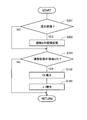
- FIG. 6 is a flowchart showing a flow of misfire suppression control and compression end temperature increase control according to this modification.
- This flow is stored in advance in the ECU 20, and is repeatedly executed at predetermined intervals.
- the process of step S101 to S103 in this flow is the same as the process of step S101 to S103 in the flow shown in FIG. 2, the description is abbreviate
- step S201 it is determined whether or not mixed combustion of CNG and light oil is being performed in the internal combustion engine 1. If a negative determination is made in step S201, then the process of step S101 is executed. In this case, the threshold value of the low load / low rotation area A in the map shown in FIG. 3 is set to a predetermined reference value.
- step S202 the threshold value of the low load low rotation region A of the map shown in FIG. 3 is set based on the ratio of CNG in the entire fuel supplied to the internal combustion engine 1. Is done. In this case, as described above, when the ratio of CNG in the entire fuel supplied to the internal combustion engine 1 is high, the low load low rotation region A is on the high load high rotation side as compared to when the CNG ratio is low. Enlarged. Next, the process of step S101 is executed.
- the present invention may be applied to an internal combustion engine in which other gas fuel and liquid fuel are mixed and burned. Also in this case, the misfire suppression control and the compression end temperature increase control as described above are executed according to the extinction distance between the gas fuel and the liquid fuel to be used.
- gas fuel for example, hydrogen gas or LPG
- liquid fuel for example, gasoline, methanol, ethanol, or the like
Landscapes
- Engineering & Computer Science (AREA)
- Chemical & Material Sciences (AREA)
- Combustion & Propulsion (AREA)
- Mechanical Engineering (AREA)
- General Engineering & Computer Science (AREA)
- Output Control And Ontrol Of Special Type Engine (AREA)
Abstract
L'invention porte sur la commande des moteurs à combustion interne. Selon l'invention, pour éviter l'apparition d'un raté d'allumage dans un moteur à combustion interne, un système de commande de moteur à combustion interne selon la présente invention est équipé d'une unité de commande de l'espace libre servant à commander de façon variable l'espace libre entre la surface supérieure du piston au point mort haut de compression et la culasse. Lorsque la distance d'extinction au moment de la mise à feu du carburant est grande, l'espace libre entre la surface supérieure du piston au point mort haut de compression et la culasse est agrandi par une unité de commande de l'espace libre, comparativement au cas où la distance d'extinction est petite (S101, S102).
Priority Applications (1)
| Application Number | Priority Date | Filing Date | Title |
|---|---|---|---|
| PCT/JP2011/054031 WO2012114482A1 (fr) | 2011-02-23 | 2011-02-23 | Système de commande de moteur à combustion interne |
Applications Claiming Priority (1)
| Application Number | Priority Date | Filing Date | Title |
|---|---|---|---|
| PCT/JP2011/054031 WO2012114482A1 (fr) | 2011-02-23 | 2011-02-23 | Système de commande de moteur à combustion interne |
Publications (1)
| Publication Number | Publication Date |
|---|---|
| WO2012114482A1 true WO2012114482A1 (fr) | 2012-08-30 |
Family
ID=46720301
Family Applications (1)
| Application Number | Title | Priority Date | Filing Date |
|---|---|---|---|
| PCT/JP2011/054031 Ceased WO2012114482A1 (fr) | 2011-02-23 | 2011-02-23 | Système de commande de moteur à combustion interne |
Country Status (1)
| Country | Link |
|---|---|
| WO (1) | WO2012114482A1 (fr) |
Cited By (3)
| Publication number | Priority date | Publication date | Assignee | Title |
|---|---|---|---|---|
| JP5469269B1 (ja) * | 2013-04-04 | 2014-04-16 | 三菱電機株式会社 | 火花点火式内燃機関の制御装置 |
| JP2015183642A (ja) * | 2014-03-25 | 2015-10-22 | 大阪瓦斯株式会社 | エンジンシステム、及びその制御方法 |
| JP2020200831A (ja) * | 2019-06-13 | 2020-12-17 | エムエーエヌ・エナジー・ソリューションズ・フィリアル・アフ・エムエーエヌ・エナジー・ソリューションズ・エスイー・ティスクランド | 大型2ストロークユニフロー掃気ガス燃料エンジン、及び、燃焼室の状態を制御する方法 |
Citations (5)
| Publication number | Priority date | Publication date | Assignee | Title |
|---|---|---|---|---|
| JPH02230949A (ja) * | 1989-03-03 | 1990-09-13 | Suzuki Motor Co Ltd | ガス燃料エンジンの圧縮比制御装置 |
| JP2000073804A (ja) * | 1998-09-01 | 2000-03-07 | Toyota Autom Loom Works Ltd | 内燃機関及びその制御装置 |
| JP2007146704A (ja) * | 2005-11-25 | 2007-06-14 | Nissan Motor Co Ltd | 副室式エンジン |
| JP2009115035A (ja) * | 2007-11-08 | 2009-05-28 | Toyota Motor Corp | 火花点火式内燃機関 |
| JP2010196578A (ja) * | 2009-02-25 | 2010-09-09 | Nissan Motor Co Ltd | 内燃機関の始動制御装置 |
-
2011
- 2011-02-23 WO PCT/JP2011/054031 patent/WO2012114482A1/fr not_active Ceased
Patent Citations (5)
| Publication number | Priority date | Publication date | Assignee | Title |
|---|---|---|---|---|
| JPH02230949A (ja) * | 1989-03-03 | 1990-09-13 | Suzuki Motor Co Ltd | ガス燃料エンジンの圧縮比制御装置 |
| JP2000073804A (ja) * | 1998-09-01 | 2000-03-07 | Toyota Autom Loom Works Ltd | 内燃機関及びその制御装置 |
| JP2007146704A (ja) * | 2005-11-25 | 2007-06-14 | Nissan Motor Co Ltd | 副室式エンジン |
| JP2009115035A (ja) * | 2007-11-08 | 2009-05-28 | Toyota Motor Corp | 火花点火式内燃機関 |
| JP2010196578A (ja) * | 2009-02-25 | 2010-09-09 | Nissan Motor Co Ltd | 内燃機関の始動制御装置 |
Cited By (4)
| Publication number | Priority date | Publication date | Assignee | Title |
|---|---|---|---|---|
| JP5469269B1 (ja) * | 2013-04-04 | 2014-04-16 | 三菱電機株式会社 | 火花点火式内燃機関の制御装置 |
| JP2015183642A (ja) * | 2014-03-25 | 2015-10-22 | 大阪瓦斯株式会社 | エンジンシステム、及びその制御方法 |
| JP2020200831A (ja) * | 2019-06-13 | 2020-12-17 | エムエーエヌ・エナジー・ソリューションズ・フィリアル・アフ・エムエーエヌ・エナジー・ソリューションズ・エスイー・ティスクランド | 大型2ストロークユニフロー掃気ガス燃料エンジン、及び、燃焼室の状態を制御する方法 |
| JP7000501B2 (ja) | 2019-06-13 | 2022-01-19 | エムエーエヌ・エナジー・ソリューションズ・フィリアル・アフ・エムエーエヌ・エナジー・ソリューションズ・エスイー・ティスクランド | 大型2ストロークユニフロー掃気ガス燃料エンジン、及び、燃焼室の状態を制御する方法 |
Similar Documents
| Publication | Publication Date | Title |
|---|---|---|
| CN103459810B (zh) | 多燃料内燃机的控制系统 | |
| US9850812B2 (en) | Engine combustion control at low loads via fuel reactivity stratification | |
| JP5569644B2 (ja) | 多種燃料内燃機関の燃料供給制御システム | |
| US20120004830A1 (en) | Controller for internal combustion engine | |
| JP5783036B2 (ja) | 内燃機関 | |
| JP2009108777A (ja) | 圧縮着火式内燃機関 | |
| US20130087123A1 (en) | Diesel-gasoline hybrid engine | |
| CN103080509A (zh) | 内燃机 | |
| JP4919922B2 (ja) | 内燃機関の制御装置 | |
| CN103748339B (zh) | 多燃料内燃机的控制系统 | |
| US20190032622A1 (en) | Control method and control device for internal combustion engine | |
| CN103477059B (zh) | 内燃机的控制装置以及方法 | |
| WO2012114482A1 (fr) | Système de commande de moteur à combustion interne | |
| JP5168177B2 (ja) | 内燃機関の制御装置 | |
| JP2008184970A (ja) | ガソリンエンジンの制御装置 | |
| JP5528141B2 (ja) | 圧縮着火内燃機関 |
Legal Events
| Date | Code | Title | Description |
|---|---|---|---|
| 121 | Ep: the epo has been informed by wipo that ep was designated in this application |
Ref document number: 11859525 Country of ref document: EP Kind code of ref document: A1 |
|
| NENP | Non-entry into the national phase |
Ref country code: DE |
|
| 122 | Ep: pct application non-entry in european phase |
Ref document number: 11859525 Country of ref document: EP Kind code of ref document: A1 |
|
| NENP | Non-entry into the national phase |
Ref country code: JP |