WO2012114664A1 - Bougie de préchauffage à capteur de pression de combustion - Google Patents
Bougie de préchauffage à capteur de pression de combustion Download PDFInfo
- Publication number
- WO2012114664A1 WO2012114664A1 PCT/JP2012/000803 JP2012000803W WO2012114664A1 WO 2012114664 A1 WO2012114664 A1 WO 2012114664A1 JP 2012000803 W JP2012000803 W JP 2012000803W WO 2012114664 A1 WO2012114664 A1 WO 2012114664A1
- Authority
- WO
- WIPO (PCT)
- Prior art keywords
- pressure sensor
- housing
- glow plug
- heater
- combustion pressure
- Prior art date
- Legal status (The legal status is an assumption and is not a legal conclusion. Google has not performed a legal analysis and makes no representation as to the accuracy of the status listed.)
- Ceased
Links
Images

Classifications
-
- F—MECHANICAL ENGINEERING; LIGHTING; HEATING; WEAPONS; BLASTING
- F23—COMBUSTION APPARATUS; COMBUSTION PROCESSES
- F23Q—IGNITION; EXTINGUISHING-DEVICES
- F23Q7/00—Incandescent ignition; Igniters using electrically-produced heat, e.g. lighters for cigarettes; Electrically-heated glowing plugs
- F23Q7/001—Glowing plugs for internal-combustion engines
-
- F—MECHANICAL ENGINEERING; LIGHTING; HEATING; WEAPONS; BLASTING
- F23—COMBUSTION APPARATUS; COMBUSTION PROCESSES
- F23Q—IGNITION; EXTINGUISHING-DEVICES
- F23Q7/00—Incandescent ignition; Igniters using electrically-produced heat, e.g. lighters for cigarettes; Electrically-heated glowing plugs
-
- F—MECHANICAL ENGINEERING; LIGHTING; HEATING; WEAPONS; BLASTING
- F02—COMBUSTION ENGINES; HOT-GAS OR COMBUSTION-PRODUCT ENGINE PLANTS
- F02P—IGNITION, OTHER THAN COMPRESSION IGNITION, FOR INTERNAL-COMBUSTION ENGINES; TESTING OF IGNITION TIMING IN COMPRESSION-IGNITION ENGINES
- F02P19/00—Incandescent ignition, e.g. during starting of internal combustion engines; Combination of incandescent and spark ignition
- F02P19/02—Incandescent ignition, e.g. during starting of internal combustion engines; Combination of incandescent and spark ignition electric, e.g. layout of circuits of apparatus having glowing plugs
- F02P19/028—Incandescent ignition, e.g. during starting of internal combustion engines; Combination of incandescent and spark ignition electric, e.g. layout of circuits of apparatus having glowing plugs the glow plug being combined with or used as a sensor
-
- G—PHYSICS
- G01—MEASURING; TESTING
- G01L—MEASURING FORCE, STRESS, TORQUE, WORK, MECHANICAL POWER, MECHANICAL EFFICIENCY, OR FLUID PRESSURE
- G01L23/00—Devices or apparatus for measuring or indicating or recording rapid changes, such as oscillations, in the pressure of steam, gas, or liquid; Indicators for determining work or energy of steam, internal-combustion, or other fluid-pressure engines from the condition of the working fluid
- G01L23/22—Devices or apparatus for measuring or indicating or recording rapid changes, such as oscillations, in the pressure of steam, gas, or liquid; Indicators for determining work or energy of steam, internal-combustion, or other fluid-pressure engines from the condition of the working fluid for detecting or indicating knocks in internal-combustion engines; Units comprising pressure-sensitive members combined with ignitors for firing internal-combustion engines
-
- F—MECHANICAL ENGINEERING; LIGHTING; HEATING; WEAPONS; BLASTING
- F02—COMBUSTION ENGINES; HOT-GAS OR COMBUSTION-PRODUCT ENGINE PLANTS
- F02D—CONTROLLING COMBUSTION ENGINES
- F02D35/00—Controlling engines, dependent on conditions exterior or interior to engines, not otherwise provided for
- F02D35/02—Controlling engines, dependent on conditions exterior or interior to engines, not otherwise provided for on interior conditions
- F02D35/023—Controlling engines, dependent on conditions exterior or interior to engines, not otherwise provided for on interior conditions by determining the cylinder pressure
-
- F—MECHANICAL ENGINEERING; LIGHTING; HEATING; WEAPONS; BLASTING
- F23—COMBUSTION APPARATUS; COMBUSTION PROCESSES
- F23Q—IGNITION; EXTINGUISHING-DEVICES
- F23Q7/00—Incandescent ignition; Igniters using electrically-produced heat, e.g. lighters for cigarettes; Electrically-heated glowing plugs
- F23Q7/001—Glowing plugs for internal-combustion engines
- F23Q2007/002—Glowing plugs for internal-combustion engines with sensing means
-
- F—MECHANICAL ENGINEERING; LIGHTING; HEATING; WEAPONS; BLASTING
- F23—COMBUSTION APPARATUS; COMBUSTION PROCESSES
- F23Q—IGNITION; EXTINGUISHING-DEVICES
- F23Q7/00—Incandescent ignition; Igniters using electrically-produced heat, e.g. lighters for cigarettes; Electrically-heated glowing plugs
- F23Q7/001—Glowing plugs for internal-combustion engines
- F23Q2007/004—Manufacturing or assembling methods
- F23Q2007/005—Manufacturing or assembling methods pressure sensors
Definitions
- the present invention relates to a glow plug, and more particularly to a glow plug with a combustion pressure sensor.
- Patent Document 1 discloses a glow plug including a multi-stage heater portion (finger) in which a front end side is formed with a small diameter and a rear end side is formed with a large diameter.
- the heater part of the glow plug described in Patent Document 1 is connected to a housing (body) via a film-like connecting member that enables the heater part to move in the axial direction.
- a sensor disposed in the glow plug detects the combustion pressure by detecting the axial displacement of the heater section.
- the problem to be solved by the present invention is to secure an area of a member for connecting the heater part and the housing in a glow plug with a combustion pressure sensor provided with a heater part having a multistage diameter. It is to provide a glow plug structure capable of improving the detection accuracy of the pressure sensor and further improving the detection accuracy of the pressure sensor.
- Application Example 1 A substantially cylindrical housing extending in the axial direction, and a rod-shaped heater portion having a rear end portion disposed in the housing, a front end portion protruding from the front end of the housing, and movable along the axial direction
- a connecting member that connects the heater portion and the housing in the housing, and enables the movement of the heater portion along the axial direction, and the heater that is provided in the housing and extends along the axial direction.
- a glow plug with a combustion pressure sensor comprising a pressure sensor for detecting a combustion pressure in accordance with the amount of movement of the part, wherein the heater part is formed with a large diameter part on the rear end side, and the large diameter part A narrow-diameter portion having a diameter smaller than that of the large-diameter portion is formed on the distal end side, and the connecting member connects the thin-diameter portion of the heater portion and the housing in the housing.
- Application Example 2 The glow plug with a combustion pressure sensor according to Application Example 1, wherein the pressure sensor is provided in a rear end side of the heater portion in the housing, and the large diameter portion and the A transmission member that is fixed to the pressure sensor and transmits a movement amount of the heater unit from the large-diameter portion to the pressure sensor; and the connecting member is a portion of the small-diameter portion that is closer to the large-diameter portion.
- a glow plug with a combustion pressure sensor characterized in that it is connected to *
- the present invention can also be configured as a method for manufacturing a glow plug with a combustion pressure sensor, an internal combustion engine including a glow plug with a combustion pressure sensor, and the like.
- connection member which connects a housing and a heater part inside a housing
- this connection member is connected to the small diameter part of a heater part. Therefore, in the direction perpendicular to the axis, the distance between the small-diameter portion of the heater portion and the inner peripheral surface of the housing should be wider than the distance between the large-diameter portion of the heater portion and the inner peripheral surface of the housing. And the area of the connecting member can be increased. Therefore, since the amount of movement of the heater portion along the axial direction can be increased, the S / N ratio of the pressure sensor can be improved and the pressure detection accuracy can be improved.
- the spring constant of a connection member can be reduced if the area of a connection member becomes large, it becomes possible to improve the durability of a connection member. Furthermore, in the said structure, although the large diameter part is provided in a housing, the site
- the large diameter part of a heater part will accommodate the rod-shaped center axis
- the narrow-diameter portion on the distal end side of the housing mainly generates heat, so that the combustion chamber can be efficiently heated.
- the glow plug has a small diameter such that the diameter of the screw portion is 9 mm or less as in Application Example 5, it is difficult to secure the area of the connecting member, and thus various effects in each of the application examples described above can be obtained. It will appear more prominently.
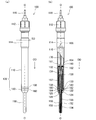
- FIG. 1 is an explanatory diagram showing a configuration of a glow plug 100 as an embodiment of the present invention.
- 1A shows the overall configuration of the glow plug 100
- FIG. 1B shows a partial cross-sectional configuration
- FIG. 2 is an enlarged cross-sectional view in the vicinity of a connecting member 180 described later.
- the lower side of the axis O of the glow plug 100 in FIGS. 1 and 2 is the front end side of the glow plug 100 and the upper side is the rear end side.
- a downward direction along the axis O of the glow plug 100 is defined as an axial direction OD.
- the glow plug 100 includes a housing 130 having a metal shell 110 and a cap member 120, and a heater unit 150. *
- the metal shell 110 is a substantially cylindrical metal member formed of carbon steel or stainless steel.
- a tool engaging portion 112 is formed at the rear end of the metal shell 110 and engages with a tool for attaching the glow plug 100 to the internal combustion engine.
- a screw portion 114 formed with a screw groove (not shown) for fixing the glow plug 100 to the cylinder head is provided on the tip side of the tool engaging portion 112.
- the diameter SD of the screw portion 114 is a nominal diameter, which is equal to or less than M9 (diameter 9 mm), and preferably M8 or M9.
- the glow plug 100 can be fixed to the internal combustion engine by engaging the tool with the tool engaging portion 112 and screwing the screw portion 114 into the plug mounting hole of the internal combustion engine.
- a plurality of wirings 116 that are electrically connected to an integrated circuit 166 (described later) and a central shaft 170 (described later) in the housing 130 are inserted into the rear end portion of the tool engaging portion 112. *
- a cap member 120 is disposed on the front end side of the metal shell 110.
- the cap member 120 is an annular metal member made of carbon steel or stainless steel.
- a cylindrical portion 122 whose outer diameter is substantially constant along the axis O is formed on the rear end side of the cap member 120, and a tapered portion 124 whose diameter decreases toward the front end is formed on the front end side.
- the heater unit 150 includes a sheath tube 152, a heating coil 154, and insulating powder 155.
- the sheath tube 152 is made of stainless steel or the like excellent in heat resistance and corrosion resistance, and has a tip end closed in a hemispherical shape and a rear end opened in the metal shell 110.
- the heating coil 154 is a wire-wound resistor and is disposed inside the distal end side of the sheath tube 152.
- a middle shaft 170 that is a metal bar-like member is inserted into the heater unit 150, and the rear end of the heating coil 154 is fixed to the tip of the middle shaft 170. Electric power is supplied to the heating coil 154 from the outside through the wiring 116 and the central shaft 170.
- the sheath tube 152 is filled with insulating powder 155 such as magnesium oxide having heat resistance in a gap with the heating coil 154.
- a seal member 156 for sealing the insulating powder 155 in the sheath tube 152 is inserted between the opened rear end of the sheath tube 152 and the middle shaft 170.
- the sheath tube 152 is subjected to a swaging process, whereby the denseness of the insulating powder 155 filled therein is enhanced, and the heat conduction efficiency is improved.
- the heater unit 150 having such a configuration is arranged such that the rear end side is disposed in the metal shell 110 and the front end side is projected from the opening 126 of the cap member 120 toward the axial direction OD. *
- the heater portion 150 is formed with a large diameter portion 157, a step portion 158, and a small diameter portion 159 by swaging the sheath tube 152 (see FIG. 2).
- the large diameter portion 157 is formed on the rear end side of the heater portion 150, and the diameter D1 thereof is, for example, about 4.0 mm.
- the small diameter portion 159 is formed on the tip side of the heater portion 150, and the diameter D2 is, for example, about 3.5 mm.
- the step portion 158 is disposed between the large-diameter portion 157 and the small-diameter portion 159, and is reduced in diameter toward the tip.
- the small-diameter portion 159 protrudes from the tip of the housing 130.
- the large diameter portion 157 and the step portion 158 are arranged in the housing 130.
- the middle shaft 170 is disposed in the large-diameter portion 157 over the entire region in the axial direction OD, and the distal end of the middle shaft 170 is located in the narrow-diameter portion 159 on the distal side of the housing 130. ing.
- a heating coil 154 is connected to the tip of the middle shaft 170, and this heating coil 154 is arranged over the tip of the sheath tube 152, so that the heater unit 150 mainly generates heat on the tip side of the housing 130. become.
- an annular pressure sensor 160 (see FIG. 1) disposed on the rear end side of the heater portion 150, and a sensor fixing member 13 for fixing the pressure sensor 160 in the housing 130. 2, a transmission sleeve 134 for transmitting the displacement along the axis O of the heater unit 150 to the pressure sensor 160, and a connecting member 180 for connecting the outer periphery of the heater unit 150 to the inside of the housing 130. ing.
- the sensor fixing member 132 is a substantially cylindrical member formed of stainless steel or the like.
- the sensor fixing member 132 is disposed along the inner periphery of the metallic shell 110, and a flange-shaped flange portion 133 is formed at the tip thereof.
- the flange portion 133 is welded to the front end surface of the metal shell 110.
- the outer periphery of the pressure sensor 160 is welded to the rear end of the sensor fixing member 132.
- the pressure sensor 160 is fixed near the central portion in the housing 130 by the sensor fixing member 132. *
- the transmission sleeve 134 is a substantially cylindrical member formed of stainless steel or the like.
- the transmission sleeve 134 is disposed between the sensor fixing member 132 and the heater unit 150.
- the distal end portion of the transmission sleeve 134 is welded to the distal end portion of the large-diameter portion 157 of the heater portion 150, and the rear end of the transmission sleeve 134 is welded to the inner peripheral portion of the annular pressure sensor 160.
- the displacement along the axis O of the heater portion 150 is transmitted to the inner peripheral portion of the pressure sensor 160 by the transmission sleeve 134.
- the connecting member 180 is an annular member having elasticity formed of stainless steel, nickel alloy, or the like.
- the connecting member 180 includes a flange-like flange portion 182 provided on the rear end side, a thin-film-like flat portion 183 provided on the front end side, and a cylindrical portion 184 that connects the flange portion 182 and the flat portion 183.
- the flange portion 182 has an upper surface (surface on the rear end side) welded to the flange portion 133 of the sensor fixing member 132, and a lower surface (surface on the front end side) welded to the rear end surface of the cap member 120.
- the flat portion 183 has a folded portion 185 that is folded toward the distal end side at the inner peripheral portion thereof.
- connection member 180 is welded to the vicinity of the rear end of the small diameter portion 159 of the heater portion 150 at the folded portion 185.
- the position on the axis O of the rear end (in other words, the front end of the step portion 158) of the small diameter portion 159 of the heater portion 150 is the connecting member 180 (flange portion 182, cylindrical portion 184, plane portion 183).
- the folded portion 185) is located in the range R occupied on the axis O.
- the heater unit 150 is connected to the housing 130 by the connecting member 180, and displacement along the axis O is allowed by the elastic force of the connecting member 180.
- the connecting member 180 also serves to ensure airtightness from the combustion chamber into the metal shell 110 by connecting the heater portion 150 and the housing 130. *
- the pressure sensor 160 (see FIG. 1) includes an annular metal diaphragm 162 provided in the center with an opening 161 through which the central shaft 170 passes, and a piezoresistive element 164 joined to the upper surface (rear end surface) of the metal diaphragm 162. And.
- the metal diaphragm 162 is formed of, for example, stainless steel.
- An integrated circuit 166 provided at a predetermined position in the housing 130 is electrically connected to the piezoresistive element 164. As described above, the rear end of the transmission sleeve 134 connected to the heater unit 150 is joined to the inner periphery of the metal diaphragm 162.
- the integrated circuit 166 detects the combustion pressure of the internal combustion engine by detecting the deformation of the metal diaphragm 162 using the piezoresistive element 164.
- the integrated circuit 166 outputs an electrical signal indicating the combustion pressure thus detected to an external ECU or the like through the wiring 116 inserted at the rear end of the metal shell 110.
- the connecting member 180 that connects the housing 130 and the heater portion 150 is connected to the small diameter portion 159 of the heater portion 150 in the housing 130. Therefore, the area of the thin flat portion 183 can be made larger than when the connecting member 180 is connected to the large diameter portion 157. As a result, even if the glow plug 100 has a relatively small diameter with a nominal diameter of the screw portion 114 of M9 or less, a sufficient amount of displacement along the axis O of the heater portion 150 can be ensured. The S / N ratio can be increased, and the detection accuracy of the combustion pressure can be improved. Furthermore, since the spring constant of the connecting member 180 can be lowered if the area of the flat portion 183 is increased, the durability of the connecting member 180 can be increased. *
- the large diameter portion 157 of the heater portion 150 is provided in the housing 130, but the portion to which the connecting member 180 is connected in the housing is the small diameter portion 159. Therefore, when transmitting the displacement of the heater unit 150 allowed by the connecting member 180 to the pressure sensor 160, a load is applied to the large-diameter portion 157 having high rigidity, and an uneven load is hardly generated. Therefore, the displacement of the heater unit 150 can be accurately transmitted to the pressure sensor 160, and the detection accuracy of the combustion pressure can be improved.
- the connecting member 180 is joined to the vicinity of the rear end of the small diameter portion 159 of the heater portion 150, and the front end of the transmission sleeve 134 is the large diameter portion 157 near the rear end of the small diameter portion 159. It is joined near the tip. Therefore, even if the connecting member 180 is connected to the small diameter portion 159 of the heater portion 150, the displacement of the heater portion 150 in the vicinity of the connecting member 180 is thicker than the thin diameter portion 159 and has high rigidity along the axis O. It is transmitted efficiently to the transmission sleeve 134. As a result, the responsiveness of the pressure sensor 160 with respect to the displacement along the axis O of the heater unit 150 can be improved, and transmission loss can be suppressed. *
- the middle shaft 170 is disposed in the large diameter portion 157 over the entire region in the axial direction OD. Since the middle shaft 170 is made of metal and has a rod shape, it has high rigidity. Therefore, the rigidity of the large-diameter portion 157 of the heater portion 150 that accommodates the middle shaft 170 is further improved, which contributes to improvement in detection accuracy of the pressure sensor. *
- the distal end of the middle shaft 170 is located in the narrow diameter portion 159 on the distal side of the housing 130, and a heating coil 154 is connected to the distal end of the middle shaft 170. Therefore, the heater unit 150 generates heat mainly on the front end side of the housing 130. Due to combustion of an internal combustion engine such as a diesel engine, soot may accumulate between the cap member 120 and the heater unit 150 in the opening 126 at the tip of the housing 130. When the soot accumulation progresses and the opening 126 is bridged by soot, the heat generated in the heater unit 150 is not used for heating the combustion chamber of the internal combustion engine, and the housing 130 passes through the crossed soot.
- an internal combustion engine such as a diesel engine
- the main part of heat generation is located on the front end side of the housing 130, that is, on the combustion chamber side. Therefore, the main part of heat generation straddles the front end part of the housing from the front end to the rear end of the heater unit 150. Compared with other glow plugs having a portion, the amount of heat radiated to the cylinder head can be reduced. Therefore, according to the glow plug 100 of the present embodiment, the combustion chamber can be efficiently heated, and the heating capability as the glow plug can be enhanced.
- the nominal diameter of the screw portion 114 is set to M9 or less, but it may be a nominal diameter of M10 or more.
- the following modifications are possible. *
- the heater unit 150 is configured by embedding the heating coil 154 in the sheath tube 152, but other configurations are possible.
- the heater unit 150 may be configured as a ceramic heater in which a conductive ceramic is embedded in an insulating ceramic.
- the heater unit 150 is formed with a two-stage diameter of a large-diameter part and a small-diameter part.
- a three-stage or more diameter may be formed.
- the part to which the connecting member 180 is connected should just be a diameter thinner than another part.
- the pressure sensor 160 is configured by the annular metal diaphragm 162 and the piezoresistive element 164.
- the configuration of the pressure sensor 160 is not limited to this, and a well-known pressure sensor employed in a glow plug with a combustion pressure sensor can be appropriately applied.
- the housing 130 and the heater unit 150 are connected by the connecting member 180 having the thin film-like flat part 183.
- the housing 130 and the heater unit 150 may be coupled by a bellows (bellows) -shaped member.
- the heater unit 150 and the pressure sensor 160 are connected via the transmission sleeve 134. However, the rear end portion of the heater unit 150 is directly connected to the pressure sensor 160. Also good. *
- power is supplied to the heater unit 150 through the middle shaft 170, but the middle shaft 170 may be omitted and power may be directly supplied from the wiring 116 to the heater unit 150.
Landscapes
- Engineering & Computer Science (AREA)
- Chemical & Material Sciences (AREA)
- Combustion & Propulsion (AREA)
- Mechanical Engineering (AREA)
- General Engineering & Computer Science (AREA)
- Physics & Mathematics (AREA)
- General Physics & Mathematics (AREA)
- Measuring Fluid Pressure (AREA)
Abstract
Priority Applications (3)
| Application Number | Priority Date | Filing Date | Title |
|---|---|---|---|
| KR1020137024476A KR101564493B1 (ko) | 2011-02-25 | 2012-02-07 | 연소 압력센서 장착 글로 플러그 |
| US13/976,565 US9784450B2 (en) | 2011-02-25 | 2012-02-07 | Glow plug with combustion pressure sensor |
| EP12748904.5A EP2679903B1 (fr) | 2011-02-25 | 2012-02-07 | Bougie de préchauffage à capteur de pression de combustion |
Applications Claiming Priority (2)
| Application Number | Priority Date | Filing Date | Title |
|---|---|---|---|
| JP2011039112A JP5838033B2 (ja) | 2011-02-25 | 2011-02-25 | 燃焼圧力センサ付きグロープラグ |
| JP2011-039112 | 2011-02-25 |
Publications (1)
| Publication Number | Publication Date |
|---|---|
| WO2012114664A1 true WO2012114664A1 (fr) | 2012-08-30 |
Family
ID=46720460
Family Applications (1)
| Application Number | Title | Priority Date | Filing Date |
|---|---|---|---|
| PCT/JP2012/000803 Ceased WO2012114664A1 (fr) | 2011-02-25 | 2012-02-07 | Bougie de préchauffage à capteur de pression de combustion |
Country Status (5)
| Country | Link |
|---|---|
| US (1) | US9784450B2 (fr) |
| EP (1) | EP2679903B1 (fr) |
| JP (1) | JP5838033B2 (fr) |
| KR (1) | KR101564493B1 (fr) |
| WO (1) | WO2012114664A1 (fr) |
Cited By (1)
| Publication number | Priority date | Publication date | Assignee | Title |
|---|---|---|---|---|
| JPWO2016080105A1 (ja) * | 2014-11-21 | 2017-06-29 | ボッシュ株式会社 | セラミックスヒータ型グロープラグの製造方法及びセラミックスヒータ型グロープラグ |
Families Citing this family (11)
| Publication number | Priority date | Publication date | Assignee | Title |
|---|---|---|---|---|
| US9683742B2 (en) * | 2012-08-09 | 2017-06-20 | Bosch Corporation | Pressure sensor integrated glow plug |
| WO2014122957A1 (fr) * | 2013-02-08 | 2014-08-14 | ボッシュ株式会社 | Bougie de départ type corps de capteur de pression, et procédé de fabrication de celle-ci |
| JP6154651B2 (ja) * | 2013-04-16 | 2017-06-28 | 日本特殊陶業株式会社 | 燃焼圧センサ付きグロープラグ及びその製造方法 |
| JP6271915B2 (ja) * | 2013-08-28 | 2018-01-31 | 日本特殊陶業株式会社 | 燃焼圧センサ付きグロープラグ及びセンサ無しグロープラグを装着した内燃機関 |
| JP6434758B2 (ja) | 2013-10-22 | 2018-12-05 | 日本特殊陶業株式会社 | グロープラグ制御装置及びグロープラグ制御方法 |
| JP2015101984A (ja) * | 2013-11-22 | 2015-06-04 | トヨタ自動車株式会社 | 内燃機関 |
| JP6302715B2 (ja) * | 2014-03-26 | 2018-03-28 | 日本特殊陶業株式会社 | ディーゼルエンジンの制御装置およびその方法 |
| JP6320209B2 (ja) * | 2014-07-15 | 2018-05-09 | 日本特殊陶業株式会社 | ディーゼルエンジンの制御装置およびその制御方法 |
| JP6370663B2 (ja) * | 2014-10-09 | 2018-08-08 | 日本特殊陶業株式会社 | グロープラグ |
| EP3064835B1 (fr) * | 2015-03-04 | 2018-04-25 | Sieva D O O Pe Spodnja Idrija | Bougie de préchauffage comprenant un capteur de charge et une membrane distale souple soudée présentant une collerette souple transversale |
| JP6666220B2 (ja) * | 2016-09-09 | 2020-03-13 | 日本特殊陶業株式会社 | 圧力センサ |
Citations (5)
| Publication number | Priority date | Publication date | Assignee | Title |
|---|---|---|---|---|
| JPS5348136A (en) * | 1976-10-12 | 1978-05-01 | Ngk Spark Plug Co Ltd | Glow plug |
| JP2006010306A (ja) * | 2004-05-26 | 2006-01-12 | Toyota Central Res & Dev Lab Inc | グロープラグ |
| JP2008536085A (ja) | 2005-04-12 | 2008-09-04 | コンティネンタル オートモーティヴ フランス | 一体化された圧力センサを備えたグロープラグ及びグロープラグのボディ |
| JP2009520941A (ja) * | 2005-12-23 | 2009-05-28 | ローベルト ボツシユ ゲゼルシヤフト ミツト ベシユレンクテル ハフツング | シース形グロープラグ |
| JP2010139148A (ja) * | 2008-12-11 | 2010-06-24 | Ngk Spark Plug Co Ltd | 燃焼圧力センサ付きグロープラグ及び内燃機関 |
Family Cites Families (13)
| Publication number | Priority date | Publication date | Assignee | Title |
|---|---|---|---|---|
| JP2004278934A (ja) * | 2003-03-17 | 2004-10-07 | Ngk Spark Plug Co Ltd | 燃焼圧検知機能付きグロープラグ |
| JP2006300046A (ja) * | 2004-08-05 | 2006-11-02 | Ngk Spark Plug Co Ltd | 燃焼圧検知機能付グロープラグ |
| DE102004063750A1 (de) * | 2004-12-29 | 2006-07-13 | Robert Bosch Gmbh | Glühstiftkerze mit integriertem Brennraumdrucksensor |
| DE102004063749A1 (de) * | 2004-12-29 | 2006-07-13 | Robert Bosch Gmbh | Stahlmembran für Brennraumdrucksensoren |
| DE102005051817B4 (de) * | 2005-10-28 | 2008-06-05 | Beru Ag | Druckmessglüheinrichtung, insbesondere Druckmessglühkerze |
| DE102006008639A1 (de) * | 2005-12-23 | 2007-06-28 | Robert Bosch Gmbh | Glühstiftkerze |
| DE102006008351A1 (de) * | 2006-02-21 | 2007-08-23 | Robert Bosch Gmbh | Druckmesseinrichtung |
| US7329836B2 (en) * | 2006-03-30 | 2008-02-12 | Ngk Spark Plug Co., Ltd. | Glow plug with O-ring seal |
| DE102006057627A1 (de) * | 2006-12-05 | 2008-06-12 | Robert Bosch Gmbh | Druckmesseinrichtung |
| DE102007049971A1 (de) * | 2007-10-18 | 2009-04-23 | Robert Bosch Gmbh | Glühstiftkerze |
| EP2679904B1 (fr) * | 2011-02-25 | 2018-07-25 | NGK Spark Plug Co., Ltd. | Bougie de préchauffage à capteur de pression de combustion |
| WO2012115082A1 (fr) * | 2011-02-25 | 2012-08-30 | 日本特殊陶業株式会社 | Bougie de préchauffage à capteur de pression de combustion |
| EP2846095B1 (fr) * | 2012-05-02 | 2018-03-21 | NGK Spark Plug Co., Ltd. | Bougie de préchauffage équipée d'un capteur de pression |
-
2011
- 2011-02-25 JP JP2011039112A patent/JP5838033B2/ja not_active Expired - Fee Related
-
2012
- 2012-02-07 KR KR1020137024476A patent/KR101564493B1/ko not_active Expired - Fee Related
- 2012-02-07 WO PCT/JP2012/000803 patent/WO2012114664A1/fr not_active Ceased
- 2012-02-07 US US13/976,565 patent/US9784450B2/en not_active Expired - Fee Related
- 2012-02-07 EP EP12748904.5A patent/EP2679903B1/fr not_active Not-in-force
Patent Citations (5)
| Publication number | Priority date | Publication date | Assignee | Title |
|---|---|---|---|---|
| JPS5348136A (en) * | 1976-10-12 | 1978-05-01 | Ngk Spark Plug Co Ltd | Glow plug |
| JP2006010306A (ja) * | 2004-05-26 | 2006-01-12 | Toyota Central Res & Dev Lab Inc | グロープラグ |
| JP2008536085A (ja) | 2005-04-12 | 2008-09-04 | コンティネンタル オートモーティヴ フランス | 一体化された圧力センサを備えたグロープラグ及びグロープラグのボディ |
| JP2009520941A (ja) * | 2005-12-23 | 2009-05-28 | ローベルト ボツシユ ゲゼルシヤフト ミツト ベシユレンクテル ハフツング | シース形グロープラグ |
| JP2010139148A (ja) * | 2008-12-11 | 2010-06-24 | Ngk Spark Plug Co Ltd | 燃焼圧力センサ付きグロープラグ及び内燃機関 |
Cited By (1)
| Publication number | Priority date | Publication date | Assignee | Title |
|---|---|---|---|---|
| JPWO2016080105A1 (ja) * | 2014-11-21 | 2017-06-29 | ボッシュ株式会社 | セラミックスヒータ型グロープラグの製造方法及びセラミックスヒータ型グロープラグ |
Also Published As
| Publication number | Publication date |
|---|---|
| JP2012177483A (ja) | 2012-09-13 |
| US20130269640A1 (en) | 2013-10-17 |
| JP5838033B2 (ja) | 2015-12-24 |
| EP2679903A1 (fr) | 2014-01-01 |
| EP2679903B1 (fr) | 2018-10-10 |
| US9784450B2 (en) | 2017-10-10 |
| KR101564493B1 (ko) | 2015-10-29 |
| KR20130124387A (ko) | 2013-11-13 |
| EP2679903A4 (fr) | 2018-03-21 |
Similar Documents
| Publication | Publication Date | Title |
|---|---|---|
| JP5838033B2 (ja) | 燃焼圧力センサ付きグロープラグ | |
| JP6511363B2 (ja) | 圧力センサ | |
| JP2008002809A (ja) | 燃焼圧センサー | |
| JP5723461B2 (ja) | 圧力センサ付きグロープラグ | |
| JP6151067B2 (ja) | 圧力センサ付きグロープラグ | |
| JP6096527B2 (ja) | グロープラグ | |
| JP5363653B2 (ja) | 燃焼圧力センサ付きグロープラグ | |
| JP5901882B2 (ja) | 燃焼圧力センサ付きグロープラグ | |
| JP5921957B2 (ja) | 圧力センサ付きグロープラグ及びその製造方法 | |
| JP2011089688A (ja) | 圧力センサ付きグロープラグ | |
| US10048153B2 (en) | Pressure sensor including variable member having rear end connected to housing at a predetermined axial position | |
| JP6166093B2 (ja) | 圧力センサ付きグロープラグ | |
| JP6370663B2 (ja) | グロープラグ | |
| JP2007078330A (ja) | 燃焼圧センサ付きグロープラグ | |
| JP6214932B2 (ja) | 圧力センサ付きグロープラグ | |
| JP2007085577A (ja) | 燃焼圧センサ付きグロープラグ | |
| JP6096581B2 (ja) | グロープラグ | |
| JP2014085022A (ja) | 圧力センサ付きセラミックグロープラグ | |
| JP2016161247A (ja) | グロープラグ |
Legal Events
| Date | Code | Title | Description |
|---|---|---|---|
| 121 | Ep: the epo has been informed by wipo that ep was designated in this application |
Ref document number: 12748904 Country of ref document: EP Kind code of ref document: A1 |
|
| WWE | Wipo information: entry into national phase |
Ref document number: 2012748904 Country of ref document: EP |
|
| WWE | Wipo information: entry into national phase |
Ref document number: 13976565 Country of ref document: US |
|
| NENP | Non-entry into the national phase |
Ref country code: DE |
|
| ENP | Entry into the national phase |
Ref document number: 20137024476 Country of ref document: KR Kind code of ref document: A |