WO2012114674A1 - Unité de génération d'espèce active et dispositif de génération d'espèce active - Google Patents
Unité de génération d'espèce active et dispositif de génération d'espèce active Download PDFInfo
- Publication number
- WO2012114674A1 WO2012114674A1 PCT/JP2012/000952 JP2012000952W WO2012114674A1 WO 2012114674 A1 WO2012114674 A1 WO 2012114674A1 JP 2012000952 W JP2012000952 W JP 2012000952W WO 2012114674 A1 WO2012114674 A1 WO 2012114674A1
- Authority
- WO
- WIPO (PCT)
- Prior art keywords
- active species
- discharge electrode
- generating unit
- insulating substrate
- hole
- Prior art date
- Legal status (The legal status is an assumption and is not a legal conclusion. Google has not performed a legal analysis and makes no representation as to the accuracy of the status listed.)
- Ceased
Links
Images


Classifications
-
- A—HUMAN NECESSITIES
- A61—MEDICAL OR VETERINARY SCIENCE; HYGIENE
- A61L—METHODS OR APPARATUS FOR STERILISING MATERIALS OR OBJECTS IN GENERAL; DISINFECTION, STERILISATION OR DEODORISATION OF AIR; CHEMICAL ASPECTS OF BANDAGES, DRESSINGS, ABSORBENT PADS OR SURGICAL ARTICLES; MATERIALS FOR BANDAGES, DRESSINGS, ABSORBENT PADS OR SURGICAL ARTICLES
- A61L2/00—Disinfection or sterilisation of materials or objects, in general; Accessories therefor
- A61L2/02—Disinfection or sterilisation of materials or objects, in general; Accessories therefor using physical processes
- A61L2/14—Plasma, i.e. ionised gases
-
- A—HUMAN NECESSITIES
- A61—MEDICAL OR VETERINARY SCIENCE; HYGIENE
- A61L—METHODS OR APPARATUS FOR STERILISING MATERIALS OR OBJECTS IN GENERAL; DISINFECTION, STERILISATION OR DEODORISATION OF AIR; CHEMICAL ASPECTS OF BANDAGES, DRESSINGS, ABSORBENT PADS OR SURGICAL ARTICLES; MATERIALS FOR BANDAGES, DRESSINGS, ABSORBENT PADS OR SURGICAL ARTICLES
- A61L9/00—Disinfection, sterilisation or deodorisation of air
- A61L9/16—Disinfection, sterilisation or deodorisation of air using physical phenomena
- A61L9/22—Ionisation
-
- F—MECHANICAL ENGINEERING; LIGHTING; HEATING; WEAPONS; BLASTING
- F24—HEATING; RANGES; VENTILATING
- F24F—AIR-CONDITIONING; AIR-HUMIDIFICATION; VENTILATION; USE OF AIR CURRENTS FOR SCREENING
- F24F8/00—Treatment, e.g. purification, of air supplied to human living or working spaces otherwise than by heating, cooling, humidifying or drying
- F24F8/10—Treatment, e.g. purification, of air supplied to human living or working spaces otherwise than by heating, cooling, humidifying or drying by separation, e.g. by filtering
- F24F8/192—Treatment, e.g. purification, of air supplied to human living or working spaces otherwise than by heating, cooling, humidifying or drying by separation, e.g. by filtering by electrical means, e.g. by applying electrostatic fields or high voltages
- F24F8/194—Treatment, e.g. purification, of air supplied to human living or working spaces otherwise than by heating, cooling, humidifying or drying by separation, e.g. by filtering by electrical means, e.g. by applying electrostatic fields or high voltages by filtering using high voltage
-
- F—MECHANICAL ENGINEERING; LIGHTING; HEATING; WEAPONS; BLASTING
- F24—HEATING; RANGES; VENTILATING
- F24F—AIR-CONDITIONING; AIR-HUMIDIFICATION; VENTILATION; USE OF AIR CURRENTS FOR SCREENING
- F24F8/00—Treatment, e.g. purification, of air supplied to human living or working spaces otherwise than by heating, cooling, humidifying or drying
- F24F8/30—Treatment, e.g. purification, of air supplied to human living or working spaces otherwise than by heating, cooling, humidifying or drying by ionisation
-
- Y—GENERAL TAGGING OF NEW TECHNOLOGICAL DEVELOPMENTS; GENERAL TAGGING OF CROSS-SECTIONAL TECHNOLOGIES SPANNING OVER SEVERAL SECTIONS OF THE IPC; TECHNICAL SUBJECTS COVERED BY FORMER USPC CROSS-REFERENCE ART COLLECTIONS [XRACs] AND DIGESTS
- Y02—TECHNOLOGIES OR APPLICATIONS FOR MITIGATION OR ADAPTATION AGAINST CLIMATE CHANGE
- Y02A—TECHNOLOGIES FOR ADAPTATION TO CLIMATE CHANGE
- Y02A50/00—TECHNOLOGIES FOR ADAPTATION TO CLIMATE CHANGE in human health protection, e.g. against extreme weather
- Y02A50/20—Air quality improvement or preservation, e.g. vehicle emission control or emission reduction by using catalytic converters
Definitions
- the present invention relates to an active species generating unit and an active species generating device.
- an active species generating apparatus having an active species generating unit that supplies active species such as radicals in the air and cleans the air by the cleaning action of the active species has been developed.
- a conventional active species generator includes a main body case, a discharge electrode, a counter electrode facing the discharge electrode, a power source for applying a voltage to the discharge electrode and the counter electrode, and an adsorption provided on the surface of the counter electrode.
- a voltage is applied between the discharge electrode and the counter electrode, and corona discharge is performed.
- the water adsorbed on the adsorbing portion was decomposed by corona discharge, and active species were generated.
- the current flowing between the discharge electrode and the counter electrode due to corona discharge tends to flow in the thickness direction of the adsorption portion that is the shortest path from the discharge electrode to the counter electrode. For this reason, there is a tendency that electrons are concentrated and flow in a narrow range near the discharge electrode.
- the concentrated active species with high concentration may cause deterioration of the adsorption part.
- active species generated in a concentrated manner may peel off the adsorbing portion and cause a spark discharge between the discharge electrode and the counter electrode, which has been required to improve safety.
- the active species generating unit of the present invention covers a flat insulating substrate, a discharge electrode disposed at a predetermined distance from the insulating substrate, a surface of the insulating substrate, and adsorbs moisture in the vicinity of the insulating substrate.
- An adsorption part, a counter electrode provided in contact with the adsorption part, and a power source for applying a voltage to the discharge electrode and the counter electrode are provided.
- the creeping distance which is the distance that the electrons move between the discharge electrode and the counter electrode
- the creeping distance becomes long. That is, electrons flow over a longer distance through the adsorbing portion, so that a spark discharge due to an instantaneous short circuit is less likely to occur, and safety is improved.
- the discharge range is expanded and active species are generated from a wider range, the active species do not peel off the adsorbing portion.
- FIG. 1 is a perspective view of a room where an active species generator according to Embodiment 1 of the present invention is installed.
- FIG. 2 is a cross-sectional view of the active species generator.
- FIG. 3 is a side view of the adsorbing part of the active species generating unit.
- FIG. 4 is a diagram showing the concept of positive corona discharge of the same active species generating unit.
- FIG. 5 is a diagram showing the concept of negative corona discharge of the active species generation unit.
- FIG. 6 is a cross-sectional view of an active species generating apparatus including an active species generating unit according to Embodiment 2 of the present invention.
- FIG. 7 is a cross-sectional view of an active species generating apparatus in which the active species generating units are arranged differently.
- FIG. 1 is a perspective view of a room where an active species generator according to Embodiment 1 of the present invention is installed.
- FIG. 2 is a cross-sectional view of the active species generator.
- FIG. 8 is a side cross-sectional view of the active species generation unit and the support member.
- FIG. 9 is a perspective view of the active species generation unit and the support member.
- FIG. 10 is a development view of the active species generation unit and the support member.
- FIG. 11 is a plan view of an insulating substrate of the active species generation unit as viewed from the discharge electrode side.
- FIG. 12 is a diagram showing the concept of positive corona discharge in the active species generating unit.
- FIG. 13 is a side cross-sectional view of the active species generation unit and the support member.
- FIG. 14 is a diagram showing the concept of negative corona discharge in the active species generating unit.
- FIG. 15 is a side sectional view of an active species generation unit and a support member according to Embodiment 3 of the present invention.
- FIG. 16 is a cross-sectional view of an active species generation unit and a support member according to Embodiment 4 of the present invention.
- FIG. 17 is an exploded perspective view of the active species generating unit.
- FIG. 18 is an exploded perspective view of the conductive portion and the insulating substrate of the active species generation unit.
- FIG. 19 is an exploded perspective view in which a conductive portion and an insulating substrate of the same active species generating unit are cut.
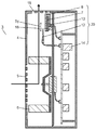
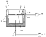
- FIG. 1 is a perspective view of a room where an active species generator according to Embodiment 1 of the present invention is installed. As shown in FIG. 1, an active species generator 3 is installed on the floor 2 of the room 1. The active species generator 3 supplies active species such as radicals into the air in the room 1. And the air in the room 1 is cleaned by the cleaning action by this active species.
- FIG. 2 is a sectional view of the active species generator according to Embodiment 1 of the present invention.
- the active species generator 3 When the active species generator 3 is activated, the air in the room 1 flows into the main body case 4 from the suction port 5 provided on the side surface of the plastic main body case 4. The air that has flowed into the main body case 4 moves to the upper part of the main body case 4 by the blower 6.
- a flat plate-shaped insulating substrate 7 made of a resin such as ceramic or fluorine is provided in the upper part of the main body case 4.
- the insulating substrate 7 is fixed to the main body case 4 by a support 18.
- the material of the insulating substrate 7 is preferably an inorganic material that is not easily corroded by ozone and radicals. That is, the insulating substrate 7 is formed from, for example, a ceramic substrate or a resin substrate.
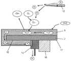
- the active species generating unit 20 includes an insulating substrate 7, a needle electrode 12 that is a discharge electrode, an adsorption portion 8, a counter electrode 13, and a power source 14 that applies a voltage to the needle electrode 12 and the counter electrode 13.
- FIG. 3 is a side view of the adsorption part of the active species generation unit according to Embodiment 1 of the present invention.
- a suction portion 8 is provided on a part of the surface of the insulating substrate 7.
- the adsorbing portion 8 has an adsorbent 9 such as zeolite of particles having an average particle diameter of 0.5 micrometers to several tens of micrometers for adsorbing water.
- the adsorption part 8 covers the surface of the insulating substrate 7 and adsorbs moisture in the vicinity of the insulating substrate 7.
- the adsorption part 8 has an adhesive 10.
- the adsorbent 9 and the insulating substrate 7 are bonded by an adhesive 10 such as colloidal silica.
- the adsorbent 9 constituting the adsorbing portion 8 has pores 11 on the surface. Therefore, the adhesive 10 may have an average particle diameter that is smaller than the average particle diameter of the adsorbent 9 such as zeolite and larger than the pores 11 opened on the surface of the zeolite. If the pores 11 are not blocked, glass powder or a silicate compound may be used as the adhesive 10.
- the adsorbent 9 in Embodiment 1 of the present invention causes water vapor in the air to be adsorbed to the pores 11. If the pores 11 have an average particle diameter that is difficult to be filled with the adhesive 10 particles, water vapor in the air is adsorbed.
- the adsorbent 9 may be a porous structure having nano-level pores 11 and capable of condensing water vapor in the pores 11 by a so-called Kelvin capillary condensation phenomenon. That is, any porous structure including silica, zeolite, desiccite, allophine, imogolite, or any one of these may be used. Further, porous alumina, porous silica, and porous titania that adsorb water by using gaps between particles may be used.
- a needle electrode 12 using a SUS needle or a tungsten needle for corona discharge is disposed at a predetermined distance of several millimeters to several tens of millimeters from the insulating substrate 7.
- the insulating substrate 7 is provided with a counter electrode 13 in contact with the adsorption portion 8.
- the counter electrode 13 is made of stainless steel such as SUS, aluminum, gold, silver, or copper.
- the counter electrode 13 is not limited to these and may be a conductive material.
- the needle electrode 12 is disposed in a state substantially parallel to the longitudinal direction 7 d of the insulating substrate 7.
- the needle electrode 12 and the insulating substrate 7 are not limited to a substantially parallel state, and the needle electrode 12 may have a slight inclination on the surface side of the insulating substrate 7 with respect to the longitudinal direction.
- the suction portion 8 is provided on a part of the surface of the insulating substrate 7, but the suction portion 8 is provided on the entire surface or the side surface of the insulating substrate 7. Also good. Further, the suction portion 8 may be disposed so as to face the needle electrode 12. Thereby, the water adsorb
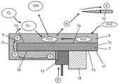
- FIG. 4 is a diagram showing a concept of a positive corona discharge of the active species generating unit according to the first embodiment of the present invention.
- the insulating substrate 7 has a rectangular shape, and has a first surface 7a, a second surface 7b, and a third surface 7c.
- the first surface 7 a faces the needle electrode 12.
- the second surface 7b is the back surface of the first surface 7a.
- the third surface 7c connects the first surface 7a and the second surface 7b.
- the insulating substrate 7 has a covered area 16 covered with the adsorption part 8 and a non-covered area 17 not covered with the adsorption part 8.
- the covering region 16 is the entire first surface 7a, a part of the second surface 7b, and one third surface 7c.
- the non-covering area 17 is a part of the second surface 7b and the other third surface 7c.
- the counter electrode 13 is located at the boundary between the covered region 16 and the non-covered region 17. The counter electrode 13 is in contact with the adsorption portion 8 and the non-covered area 17.
- the current from the needle electrode 12 toward the counter electrode 13 flows from the needle electrode 12 through the suction portion 8 covering the third surface 7c after flowing through the suction portion 8 covering the first surface 7a. Subsequently, the current flows through the adsorption portion 8 covering the second surface 7 b and then reaches the counter electrode 13.
- the creepage distance which is the distance traveled by the electrons, is long, so that no spark discharge occurs and safety is improved.
- an air flow called ion wind is generated from the tip of the needle electrode 12.
- This airflow flows from the tip of the needle electrode 12 toward the insulating substrate 7. Dust or the like tends to adhere to the windward side of the insulating substrate 7 in the airflow direction.
- the non-covering area 17 is preferably located closer to the windward side in the airflow direction of the insulating substrate 7. As a result, even if dust, oil, carbon, or the like adheres to the third surface 7c on the windward side of the insulating substrate 7 and the insulating property is lowered, the uncovered area 17 is present, so the needle electrode 12 and the counter electrode 13 The current flowing between them cannot pass through the uncovered area 17. Therefore, the current flows from the needle electrode 12 through the suction portion 8 that covers the third surface 7c on the leeward side, then flows through the suction portion 8 that covers the second surface 7b, and finally reaches the counter electrode 13.
- the insulating substrate 7 may be a ceramic substrate or a resin substrate such as fluorine.
- the ceramic substrate may be a substrate containing any one of silica, aluminum, and magnesium, or an alumina substrate.
- the insulating substrate 7 may be an inorganic or fluororesin that is not easily corroded by ozone and radicals.
- the surface resistance of the suction portion 8 that covers the surface of the insulating substrate 7 is preferably 10 6 ⁇ / ⁇ to 10 10 ⁇ / ⁇ .
- the ceramic insulating substrate 7 and the adsorbent 9 are bonded by an adhesive 10.
- the surface of the adsorbent 9 has nano-level pores 11 shown in FIG. It is known that moisture in the air (H 2 O) is adsorbed when water vapor is condensed in the pores 11 (Kelvin's capillary condensation phenomenon). As a result, moisture in the air is adsorbed to the adsorbing portion 8 such as zeolite, and the electrons (e) easily flow.
- the counter electrode 13 may be provided in contact with the second surface 7b or the third surface 7c. As a result, when electrons flowing from the needle electrode 12 flow along the first surface 7a of the insulating substrate 7, the creeping distance is increased, so that spark discharge hardly occurs.
- the needle electrode 12 is applied positively, but the voltage applied to the needle electrode 12 may be positive or negative.
- FIG. 5 is a diagram showing a concept of negative corona discharge of the active species generating unit according to Embodiment 1 of the present invention.
- a negative voltage is applied to the needle electrode 12
- a strong electric field is formed on the surface of the needle electrode 12.
- free electrons (e) are emitted into the air.
- the insulating substrate 7 in contact with the counter electrode 13 is on the plus side. As a result, electrons move, and a current flows from the counter electrode 13 to the needle electrode 12.
- the electrons (e) emitted from the needle electrode 12 to the air are attracted to the strong electric field of the counter electrode 13 by a strong force, so that the electrons move at high speed and collide with molecules in the air.
- an oxygen molecule anion (O 2 ⁇ ) in which one electron is added to the oxygen molecule is generated.
- oxygen molecular anions react with water molecules (H 2 O) adsorbed on the surface of the insulating substrate 7 to generate OH radicals (.OH).
- the OH radicals (active species) generated as shown in FIGS. 4 and 5 are exhausted into the room from the exhaust port 15 of the active species generator 3 by the ventilation from the blower 6 of FIG.
- air containing this OH radical is supplied into the room 1, bacteria in the air are inactivated. Also, the odor in the air is decomposed and removed.
- FIG. 6 is a cross-sectional view of an active species generator according to Embodiment 2 of the present invention
- FIG. 7 is a cross-sectional view of an example in which the active species generator is arranged differently.
- the main body case 4 is divided into an air passage portion 22 that communicates the suction port 5 and the exhaust port 15 and a space portion 23 by a partition plate portion 21 that is positioned substantially in the center. Yes.
- the blower section 24 is formed by an electric motor 25 fixed to the partition plate section 21, a blade section 26 rotated by the electric motor 25, and a casing section 27 surrounding the blade section 26.
- the intake port 28 of the casing portion 27 faces the intake port 5 of the main body case 4. The air sucked from the suction port 5 by the blower 24 is blown to the exhaust port 15 through a part of the active species generation unit 20.
- FIG. 8 is a side sectional view of the active species generating unit and the support member according to Embodiment 2 of the present invention
- FIG. 9 is a perspective view of the active species generating unit and the support member
- FIG. 10 is a diagram of the active species generating unit and the support member.
- FIG. 11 is a plan view when the insulating substrate of the active species generation unit is viewed from the discharge electrode side.
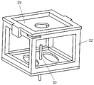
- the flat insulating substrate 29 has a hole portion 31 opened substantially at the center.
- An end portion of the insulating substrate 29 is fixed to the partition plate portion 21 via a support member 32.
- the support member 32 has a cylindrical shape or a box shape that supports the discharge electrode 30 and the counter electrode 13.
- the insulating substrate 29 is provided inside the support member 32.
- the active species generator 3 of FIG. 6 a part of the air sucked from the suction port 5 by the blower 24 passes through the periphery of the discharge electrode 30 and is blown to the exhaust port 15 through the hole 31.
- the active species generator 33 in FIG. 7 the hole 31 faces the exhaust port 15.
- the material of the insulating substrate 29 is the same as that of the insulating substrate 7 of the first embodiment.
- the surface resistance of the insulating substrate 29 is desirably 10 10 ⁇ / ⁇ or more.
- the discharge electrode 30 is disposed to face the first surface 29 a of the insulating substrate 29 and the hole 31. Further, the discharge electrode 30 is disposed on the windward side of the insulating substrate 29 in the air blowing direction from the suction port 5 to the exhaust port 15 by the blower 24. In FIG. 7, the discharge electrode 30 extends in parallel with the blowing direction of the air blown by the blower 24.
- the tip 30a of the discharge electrode 30 is located outside the hole 31 with a predetermined distance of about several millimeters to several tens of millimeters from the insulating substrate 29. Further, the center of the tip 30 a is located on the substantially center line 31 a of the hole 31.
- the counter electrode 13 is fixed to the peripheral edge of the insulating substrate 29.
- the surface resistance of the counter electrode 13 is desirably 10 ⁇ 1 ⁇ / ⁇ or less.
- the power supply 14 is located in the space 23 and applies a voltage to the discharge electrode 30 and the counter electrode 13.
- the suction portion 8 is provided on the first surface 29 a, that is, the windward side surface of the insulating substrate 29 in the blowing direction of the air blown by the blowing portion 24, and the inner surface 31 b of the hole portion 31, and is in contact with the counter electrode 13. ing.
- the surface resistance of the adsorption part 8 is preferably 10 6 ⁇ / ⁇ to 10 10 ⁇ / ⁇ .
- FIG. 12 is a diagram showing the concept of the positive corona discharge in the active species generating unit according to the second embodiment of the present invention.
- a positive voltage is applied to the discharge electrode 30 as shown in FIG. 12 will be described.
- FIG. 12 when a discharge voltage is applied to discharge electrode 30 at a plus of about 3 kV to 10 kV, a strong electric field is formed on the surface of discharge electrode 30 as in the first embodiment of the present invention. Since a positive high voltage is applied to the discharge electrode 30, free electrons (e) existing in the air flow into the discharge electrode 30.
- the counter electrode 13 is in a minus state, electrons (e) flow from the counter electrode 13 to the discharge electrode 30. This state is corona discharge, and OH radicals (.OH) are generated by this corona discharge.
- the feature of the second embodiment of the present invention is that the adsorbing portion 8 is provided on the inner surface 31 b of the hole 31 of the insulating substrate 29 and the first surface 29 a of the insulating substrate 29. . Furthermore, the tip 30 a of the discharge electrode 30 is located outside the hole 31, and the tip center 30 c is located on the substantially center line 31 a of the hole 31. Thereby, when a high voltage is applied between the discharge electrode 30 and the counter electrode 13, the current flowing between the discharge electrode 30 and the counter electrode 13 is discharged from the discharge electrode 30 to the discharge electrode provided on the insulating substrate 29. After flowing through the suction portion 8 located around 30, it reaches the counter electrode 13.
- the suction part 8 is located in the circumferential direction of the hole 31 with the discharge electrode 30 as the center. Therefore, current is dispersed and discharged over a wide range of the adsorbing portion 8, and active species are stably generated.
- the discharge portion of the cylindrical rod-like discharge electrode 30 has a circular cross-sectional shape at the tip 30a, and thus discharge is generated by being dispersed in a wide range in the circumferential direction around the discharge electrode 30.
- the current is dispersed over a wide range of the adsorption unit 8, the amount of active species such as OH radicals generated increases.
- the discharge electrode 30 is applied positively, but the voltage applied to the discharge electrode 30 may be positive or negative.
- the suction portion 8 is provided on a part of the surface of the insulating substrate 29, but the suction portion 8 is provided on the entire surface or the side surface of the insulating substrate 29. Also good. Thereby, the water adsorb
- the tip 30a of the discharge electrode 30 is positioned at the approximate center of the outer side of the hole 31, even when the discharge electrode 30 is bent, the tip 30a of the discharge electrode 30 is not in direct contact with the suction portion 8 and safety is ensured. Will improve.
- the tip 30a of the discharge electrode 30 may be positioned approximately at the outer center of the hole 31, and the tip 30a of the discharge electrode 30 and the suction portion 8 may have a predetermined distance. By setting the predetermined distance to a distance at which no spark is generated, the occurrence of spark is suppressed even when the discharge electrode 30 is bent.
- FIG. 13 is a sectional side view of the active species generating unit and the support member according to the second embodiment of the present invention.
- the effect that the center of the tip 30a of the discharge electrode 30 is positioned substantially at the outer center of the hole 31 will be described with reference to FIG.
- the distance between the discharge electrode 30 and the suction part 8 is a
- the distance from the tip 30 a of the discharge electrode 30 to the hole 31 is b
- the distance from the tip 30 a of the discharge electrode 30 to the suction part Let L be the distance to 8.
- ⁇ d is the displacement in the horizontal direction when the discharge electrode 30 is displaced due to vibration during use and error during installation.
- the discharge electrode 30 is displaced by a displacement ⁇ d
- the distance L becomes a ⁇ d and the discharge does not occur uniformly. . Therefore, the generation amount of active species may be reduced.
- the displacement ⁇ d is further increased, the discharge electrode 30 and the suction portion 8 may come into contact with each other, which is not preferable from the viewpoint of safety, such as the occurrence of sparks when a high voltage is applied.
- the distance L is represented by the relational expression ⁇ (a ⁇ d) 2 + b 2 ⁇ 1/2. Compared with the case where the discharge electrode 30 is inside the hole 31, the change in the distance L can be reduced. In this case, since the discharge electrode 30 and the adsorption
- the distance L changes by 1 mm.
- the discharge electrode 30 is formed of a single material. Thereby, the durability of the discharge electrode 30 is improved as compared with the case where the treatment such as plating is performed.
- the cross-sectional shape of the tip 30a of the discharge electrode 30 and the cross-sectional shape of the hole 31 are the same circular shape. That is, the distance between the tip 30a of the discharge electrode 30 and the inner surface 31b with the hole 31 is uniform. As a result, the current is dispersed over a wide range of the adsorbing portion 8 and the discharge portion of the discharge electrode 30 is also dispersed and discharged from the wide range, so that the deterioration of the discharge electrode 30 is suppressed and active species are stably generated.
- the thickness of the suction portion 8 on the inner surface 31 b of the hole portion 31 is larger than the thickness of the suction portion 8 on the first surface 29 a of the insulating substrate 29. Accordingly, the amount of moisture adsorbed on the adsorption portion 8 on the inner surface 31 b of the hole 31 is larger than that on the adsorption portion 8 on the first surface 29 a of the insulating substrate 29. Therefore, current flows more easily through the suction portion 8 of the inner surface 31 b of the hole portion 31 than through the suction portion 8 of the first surface 29 a of the insulating substrate 29.
- the current flowing between the discharge electrode 30 and the counter electrode 13 by corona discharge tends to flow in the shortest path from the discharge electrode 30 to the counter electrode 13.
- the suction portion 8 on the inner surface 31 b of the hole portion 31 is farther from the tip 30 a of the discharge electrode 30 than the suction portion 8 on the first surface 29 a of the insulating substrate 29.
- the inner surface 31b has a large amount of moisture adsorbed, current flows more easily than the first surface 29a. That is, the current that flows between the discharge electrode 30 and the counter electrode 13 due to corona discharge does not flow only to the suction portion 8 of the first surface 29a of the shortest path, but flows to the suction portion 8 of the inner surface 31b of the hole portion 31. Is also considered to flow easily. That is, since the current is easily dispersed over a wide range of the entire adsorption unit 8, the amount of OH radicals generated increases.
- the first distance 34 between the tip 30a of the discharge electrode 30 and the counter electrode 13 is longer than the second distance 35 between the tip 30a of the discharge electrode 30 and the adsorption portion 8.
- the current flowing between the discharge electrode 30 and the counter electrode 13 flows, for example, from the discharge electrode 30 through the suction portion 8 that covers the first surface 29a after flowing through the suction portion 8 that covers the inner surface 31b.
- the counter electrode 13 In other words, since the creepage distance becomes long, no spark discharge occurs and safety is improved.
- the counter electrode 13 may be provided on the second surface 29 b located on the back side of the first surface 29 a in the insulating substrate 29. Alternatively, the counter electrode 13 may be provided in contact with the third surface 29c between the first surface 29a and the second surface 29b. As a result, when electrons flowing from the discharge electrode 30 flow along the surface of the insulating substrate 29, the creeping distance is increased, so that spark discharge hardly occurs.
- FIG. 14 is a diagram showing the concept of negative corona discharge in the active species generating unit according to Embodiment 2 of the present invention.
- a negative discharge voltage of about 3 KV to 10 KV
- a strong electric field is formed on the surface of the discharge electrode 30.
- free electrons (e) are emitted into the air.
- the insulating substrate 29 in contact with the counter electrode 13 is on the plus side. As a result, a current flows from the counter electrode 13 to the discharge electrode 30 due to the movement of the electrons (e).
- the electrons (e) emitted from the discharge electrode 30 to the air are attracted to the strong electric field of the counter electrode 13 by a strong force, so that the electrons move at high speed and collide with molecules in the air.
- oxygen molecule anions (O 2 ⁇ ) in which one electron is added to the oxygen molecules are generated.
- oxygen molecule anions react with water molecules (H 2 O) adsorbed on the surface of the insulating substrate 29 to generate OH radicals (.OH).
- the OH radicals (active species) generated as shown in FIGS. 12 and 14 are supplied into the room from the exhaust port 15 by the air blowing from the air blowing unit 24 of FIG. 6 or FIG.
- the bacteria in the air are inactivated.
- the odor in the air is decomposed and removed, and the deodorizing effect is exhibited.
- FIG. 15 is a side sectional view of an active species generation unit and a support member according to Embodiment 3 of the present invention.
- the insulating substrate 40 has a first surface 40 a, a second surface 40 b, and an expanding inclined surface 40 c that expands with respect to the discharge electrode 30. Further, the insulating substrate 40 has a hole 41 having a widened inclined surface 40c.
- the spread inclined surface 40c is a surface that is inclined from the first surface 40a toward the second surface 40b.
- the adsorbing portion 8 is provided on the expansion inclined surface 40 c and the first surface 40 a, and the discharge electrode 30 is disposed perpendicular to the hole portion 41.
- the shape of the insulating substrate 40 is a quadrangle in the third embodiment of the present invention, but other shapes such as a circle, a rectangle, and a hexagon may be used as long as the area for providing the suction portion 8 is provided. Good.
- the hole 41 of the insulating substrate 40 may be circular.
- ion wind generated from the tip 30 a of the discharge electrode 30 efficiently passes through the circular hole 41 and is released into the air blown by the blower 6. Therefore, active species generated on the surface of the adsorption unit 8 covering the insulating substrate 40 move from the surface of the adsorption unit 8 and are easily diffused.
- the counter electrode 13 is disposed so as to contact the insulating substrate 40 and the suction portion 8. As a result, the current flowing between the discharge electrode 30 and the counter electrode 13 reaches the counter electrode 13 after flowing from the discharge electrode 30 through the suction portion 8 that covers the insulating substrate 40. That is, since the creepage distance becomes long, no spark discharge occurs and safety can be improved.
- the film thickness of the adsorption part 8 covering the insulating substrate 40 is uniform.
- the suction part 8 is formed by applying a semiconductive ink to the surface of the insulating substrate 40 with a screen printing squeegee.
- the semiconductive ink includes the adsorbent 9 shown in FIG. 3 such as zeolite and the adhesive 10 such as colloidal silica, and is mixed or dissolved in a solvent.
- the squeegee passes through the hole 41 of the insulating substrate 40 through the screen, the semiconductive ink is pushed out to the spread inclined surface 40c.
- the semiconductive ink forms a curved surface whose film thickness increases as it approaches the slope center 40d of the expansion slope 40c.
- the expansion inclined surface 40c is covered by the suction portion 8.
- tip 30a of the discharge electrode 30 increases, and the surface area of the adsorption
- attached on the expansion inclination surface 40c increases.
- the tip center 30 c of the discharge electrode 30 may be positioned on the substantially center line 41 a of the hole 41. That is, the discharge electrode 30 may have its longitudinal center axis positioned on the approximate center line 41 a of the projection surface of the hole 41. Thereby, when a high voltage is applied to the discharge electrode 30, the ionic wind generated from the tip 30 a of the discharge electrode 30 flows toward the substantially center of the hole 41 of the insulating substrate 40, so that the ionic wind is in the insulating substrate 40. Is not obstructed.
- the active species generated on the surface of the adsorption unit 8 covering the insulating substrate 40 moves from the surface of the adsorption unit 8, It becomes easy to diffuse.
- the adsorbing portion 8 forms a curved surface whose film thickness increases as it approaches the inclined surface center 40d of the expanded inclined surface 40c from the opposite side of the discharge electrode 30.
- the amount of active species generated increases on the side of the hole 41 close to the discharge electrode 30, so that many active species are supplied to the ion wind passing through the hole 41.
- an insulating coating 42 may be provided on the surface of the counter electrode 13.
- the insulating coating 42 can prevent electrons from directly reaching the counter electrode 13 from the discharge electrode 30 and causing a spark discharge. This ensures safety even when a sufficient creepage distance cannot be ensured.
- a method of adhering an insulating tape such as a fluororesin or a vinyl chloride resin, a method of applying a glass paste or a ceramic adhesive, and drying and firing are used.
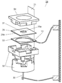
- FIG. 16 is a cross-sectional view of an active species generating unit and a support member according to Embodiment 4 of the present invention.
- the active species generating unit 58 is formed of an insulating substrate 29, a discharge electrode 30, an adsorption portion 8, a conductive portion 53, a counter electrode 13, a power source 14, and a fixed lid 54. ing.
- FIG. 17 is an exploded perspective view of an active species generating unit according to Embodiment 4 of the present invention
- FIG. 18 is an exploded perspective view of a conductive portion and an insulating substrate of the active species generating unit.
- the discharge electrode 30 is disposed to face the first surface 29 a of the insulating substrate 29.
- the suction portion 8 is provided on the inner surface 31b and the first surface 29a of the hole portion 31. Further, the shape of the suction portion 8 is a ring shape when viewed from the discharge electrode 30 side.
- the conductive portion 53 covers the outer periphery 8 a of the suction portion 8 and is electrically connected to the counter electrode 13 and the suction portion 8.
- the counter electrode 13 is provided at one corner of the conductive portion 53 and is electrically connected to the conductive portion 53.
- the flat insulating substrate 29 has a hole 31 at substantially the center. An end portion of the insulating substrate 29 is fixed to the partition plate portion 21 via a support member 32.
- the conductive portion 53 is a rectangular metal flat plate, and has a through hole 51 that is larger than the hole portion 31 and smaller than the outer periphery 8 a of the suction portion 8.
- the surface resistance of the counter electrode 13 is desirably 10 ⁇ 1 ⁇ / ⁇ or less.
- the conductive portion 53 can be easily positioned in the assembly process of the active species generating unit 58.
- the active species generating unit 58 includes a conductive portion 53 made of a metallic flat plate covering the outer peripheral portion of the adsorption portion 8 and the counter electrode 13 electrically connected to the conductive portion 53. It is a point provided. Thereby, when a high voltage is applied between the discharge electrode 30 and the counter electrode 13, the current flows from the discharge electrode 30 through the adsorption part 8 and the conductive part 53 and then reaches the counter electrode 13.
- the adsorbing portion 8 since the adsorbing portion 8 is located around the discharge electrode 30 in the circumferential direction, the current is dispersed in a wide range of the adsorbing portion 8 and active species are stably generated in a wide range. Further, the discharge portion of the cylindrical rod-shaped discharge electrode 30 has a circular cross-sectional shape at the tip 30a, so that discharge occurs in a wide range in the circumferential direction around the discharge electrode 30. As a result, compared to the case where the needle-like discharge electrode 30 having a sharp tip 30a is used, local discharge concentration is less likely to occur, deterioration of the discharge electrode 30 is suppressed, and active species are stably generated.
- the current flows so as to spread to the conductive portion 53, the current is concentrated in a narrow range of the adsorption portion 8, there is no generation of intensive active species, and deterioration of the adsorption portion 8 is suppressed.
- the conductive portion 53 is made of a metallic flat plate. Therefore, compared to the case where the conductive portion 53 is formed by a printing method using conductive ink, deterioration due to discharge of the conductive portion 53 and deterioration of the adsorption portion 8 are suppressed, and active species are stably generated.
- the material of the conductive portion 53 may be any of SUS316L, SUS316, SUS304, and anodized aluminum. Since these metals have high resistance to active species such as ozone, the counter electrode 13 is not easily corroded by active species such as ozone, and the durability of the conductive portion 53 is improved.
- the conductive portion 53 is not limited to these materials, and may be a conductive material.
- the surface resistance of the conductive portion 53 is desirably 10 ⁇ 1 ⁇ / ⁇ or less.
- the cross-sectional shape of the tip 30a of the discharge electrode 30, the shape of the hole portion 31, and the through hole 51 of the conductive portion 53 are circular. And the center line 30b of the front-end
- the through hole 51 is larger than the hole portion 31.
- the distance between the periphery of the tip 30a of the discharge electrode 30, the inner surface 31b of the hole 31 and the periphery of the through hole 51 becomes uniform.
- the current is uniformly distributed over a wide range of the suction portion 8, and the discharge electrode 30 is also uniformly dispersed from the wide range and discharged. Therefore, local discharge at the tip 30a of the discharge electrode 30 is suppressed, and durability of the discharge electrode 30 is improved.
- the current is uniformly distributed over a wide range of the suction portion 8, and the current flows so as to spread from the suction portion 8 to the conductive portion 53. Therefore, current concentrates in a narrow range of the adsorbing unit 8 and active species are not generated intensively, so that deterioration of the adsorbing unit 8 is suppressed. And since an electric current disperse
- the distance between the tip 30a of the discharge electrode 30 and the counter electrode 13 is longer than the distance between the tip 30a of the discharge electrode 30 and the inner surface 31b of the hole 31.
- the current flowing between the discharge electrode 30 and the counter electrode 13 flows from the discharge electrode 30 through the adsorption portion 8 that covers the inner surface 31 b of the hole 31. Thereafter, the current flows through the adsorption portion 8 via the inner surface 31 b and further reaches the counter electrode 13 via the conductive portion 53. That is, since the creepage distance becomes long, no spark discharge occurs and safety is improved.
- the surface resistivity of the conductive portion 53 is smaller than the surface resistivity of the attracting portion 8. Specifically, the surface resistivity of the adsorption portion 8 is 10 6 ⁇ / ⁇ to 10 10 ⁇ / ⁇ , the surface resistivity of the conductive portion 53 is 10 6 ⁇ / ⁇ or less, and the surface resistivity of the counter electrode 13 is 10 ⁇ . 1 ⁇ / ⁇ or less is desirable.
- the current flows from the discharge electrode 30 through the adsorption portion 8, then flows through the conductive portion 53, and then reaches the counter electrode 13.
- the surface resistivity of the conductive portion 53 is smaller than the surface resistivity of the attracting portion 8, the current that has flowed to the peripheral portion of the attracting portion 8 easily reaches the counter electrode 13 through the conductive portion 53.
- the current is distributed over a wide range of the adsorption part 8 and flows to the conductive part 53. Therefore, current concentrates in a narrow range of the adsorption unit 8 and active species are not generated intensively, and deterioration of the adsorption unit 8 is suppressed.
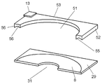
- FIG. 19 is an exploded perspective view in which the conductive part and the insulating substrate of the active species generating unit according to the fourth embodiment of the present invention are cut.
- the conductive portion 53, the outer peripheral portion 52 and the through hole 51 are formed by punching.
- a convex portion 56 is formed on the lower punching lower surface 55 of each cutting edge.
- the conductive portion 53 and the insulating substrate 29 are arranged such that the convex portion 56 is in contact with the suction portion 8.
- the convex portion 56 is disposed at a position in contact with the attracting portion 8, so that the convex portion 56 comes into contact with the attracting portion 8, so that electrons are passed from the attracting portion 8 through the convex portion 56. Hence flows.
- the active species generating unit of the present invention is expected to be used as an air purifier.
Landscapes
- Engineering & Computer Science (AREA)
- Health & Medical Sciences (AREA)
- Combustion & Propulsion (AREA)
- Mechanical Engineering (AREA)
- General Engineering & Computer Science (AREA)
- Chemical & Material Sciences (AREA)
- Life Sciences & Earth Sciences (AREA)
- Epidemiology (AREA)
- Animal Behavior & Ethology (AREA)
- General Health & Medical Sciences (AREA)
- Public Health (AREA)
- Veterinary Medicine (AREA)
- Plasma & Fusion (AREA)
- Physics & Mathematics (AREA)
- Disinfection, Sterilisation Or Deodorisation Of Air (AREA)
Abstract
L'invention concerne une unité de génération d'espèce active comprenant un substrat isolant en forme de plaque, une électrode de décharge qui est disposée de façon à être séparée du substrat isolant par une distance prescrite, une unité d'adsorption qui recouvre la surface du substrat isolant et adsorbe l'humidité près du substrat d'isolation, une contre-électrode disposée en contact avec l'unité d'adsorption et une alimentation en courant qui applique une tension à une électrode de décharge et à la contre-électrode.
Priority Applications (1)
| Application Number | Priority Date | Filing Date | Title |
|---|---|---|---|
| CN201280010048.XA CN103402553B (zh) | 2011-02-22 | 2012-02-14 | 活性种产生单元以及活性种产生装置 |
Applications Claiming Priority (10)
| Application Number | Priority Date | Filing Date | Title |
|---|---|---|---|
| JP2011-035666 | 2011-02-22 | ||
| JP2011035666A JP5873960B2 (ja) | 2011-02-22 | 2011-02-22 | 活性種発生装置 |
| JP2011084290A JP5810259B2 (ja) | 2011-04-06 | 2011-04-06 | 活性種発生装置 |
| JP2011-084290 | 2011-04-06 | ||
| JP2011-084291 | 2011-04-06 | ||
| JP2011084289 | 2011-04-06 | ||
| JP2011-084289 | 2011-04-06 | ||
| JP2011084291A JP5810260B2 (ja) | 2011-04-06 | 2011-04-06 | 活性種発生装置 |
| JP2011137979A JP2013000531A (ja) | 2011-06-22 | 2011-06-22 | 活性種発生装置 |
| JP2011-137979 | 2011-06-22 |
Publications (1)
| Publication Number | Publication Date |
|---|---|
| WO2012114674A1 true WO2012114674A1 (fr) | 2012-08-30 |
Family
ID=46720470
Family Applications (1)
| Application Number | Title | Priority Date | Filing Date |
|---|---|---|---|
| PCT/JP2012/000952 Ceased WO2012114674A1 (fr) | 2011-02-22 | 2012-02-14 | Unité de génération d'espèce active et dispositif de génération d'espèce active |
Country Status (2)
| Country | Link |
|---|---|
| CN (1) | CN103402553B (fr) |
| WO (1) | WO2012114674A1 (fr) |
Cited By (3)
| Publication number | Priority date | Publication date | Assignee | Title |
|---|---|---|---|---|
| CN103368077A (zh) * | 2013-07-01 | 2013-10-23 | 海信容声(广东)冰箱有限公司 | 一种负离子器、负离子风装置及冰箱除臭装置 |
| WO2019081580A1 (fr) * | 2017-10-28 | 2019-05-02 | Ancilia Protect Ltd | Ioniseur équipé d'un accélérateur de flux ionique notamment pour la protection contre les moustiques |
| RU2778068C2 (ru) * | 2017-10-28 | 2022-08-15 | Ансилиа Протект Лтд | Ионизатор, оборудованный ускорителем ионного потока, в частности, чтобы защищать от москитов |
Families Citing this family (1)
| Publication number | Priority date | Publication date | Assignee | Title |
|---|---|---|---|---|
| JP7228764B2 (ja) * | 2019-09-24 | 2023-02-27 | パナソニックIpマネジメント株式会社 | 放電装置及び電極装置 |
Citations (3)
| Publication number | Priority date | Publication date | Assignee | Title |
|---|---|---|---|---|
| JPH08227789A (ja) * | 1995-02-22 | 1996-09-03 | Midori Anzen Co Ltd | 樹脂電極 |
| JP2005192822A (ja) * | 2004-01-08 | 2005-07-21 | Matsushita Electric Ind Co Ltd | 浄化方法と浄化装置 |
| JP2006320613A (ja) * | 2005-05-20 | 2006-11-30 | Mitsubishi Electric Corp | 空気清浄装置 |
Family Cites Families (2)
| Publication number | Priority date | Publication date | Assignee | Title |
|---|---|---|---|---|
| CN101927026A (zh) * | 2009-06-24 | 2010-12-29 | 上海科林环保工程技术有限公司 | 等离子体空气除尘灭菌消毒装置 |
| CN102218153A (zh) * | 2010-04-13 | 2011-10-19 | 杭州盛大高科技机电有限公司 | 等离子体和静电除尘复合式空气净化消毒器 |
-
2012
- 2012-02-14 WO PCT/JP2012/000952 patent/WO2012114674A1/fr not_active Ceased
- 2012-02-14 CN CN201280010048.XA patent/CN103402553B/zh active Active
Patent Citations (3)
| Publication number | Priority date | Publication date | Assignee | Title |
|---|---|---|---|---|
| JPH08227789A (ja) * | 1995-02-22 | 1996-09-03 | Midori Anzen Co Ltd | 樹脂電極 |
| JP2005192822A (ja) * | 2004-01-08 | 2005-07-21 | Matsushita Electric Ind Co Ltd | 浄化方法と浄化装置 |
| JP2006320613A (ja) * | 2005-05-20 | 2006-11-30 | Mitsubishi Electric Corp | 空気清浄装置 |
Cited By (5)
| Publication number | Priority date | Publication date | Assignee | Title |
|---|---|---|---|---|
| CN103368077A (zh) * | 2013-07-01 | 2013-10-23 | 海信容声(广东)冰箱有限公司 | 一种负离子器、负离子风装置及冰箱除臭装置 |
| WO2019081580A1 (fr) * | 2017-10-28 | 2019-05-02 | Ancilia Protect Ltd | Ioniseur équipé d'un accélérateur de flux ionique notamment pour la protection contre les moustiques |
| FR3072891A1 (fr) * | 2017-10-28 | 2019-05-03 | Ancilia Protect Ltd | Ioniseur equipe d’un accelerateur de flux ionique notamment pour la protection contre les moustiques |
| RU2778068C2 (ru) * | 2017-10-28 | 2022-08-15 | Ансилиа Протект Лтд | Ионизатор, оборудованный ускорителем ионного потока, в частности, чтобы защищать от москитов |
| US11510406B2 (en) | 2017-10-28 | 2022-11-29 | Ancilia Protect Ltd | Ioniser equipped with an ionic flow accelerator in particular to protect against mosquitoes |
Also Published As
| Publication number | Publication date |
|---|---|
| CN103402553B (zh) | 2015-04-08 |
| CN103402553A (zh) | 2013-11-20 |
Similar Documents
| Publication | Publication Date | Title |
|---|---|---|
| JP3852429B2 (ja) | 空気清浄機 | |
| JP6581661B2 (ja) | 多孔質誘電体を含むプラズマ発生源 | |
| JP3438054B2 (ja) | イオン発生素子 | |
| CN1292799C (zh) | 空气清净机 | |
| CN104428012B (zh) | 放电单元以及使用了其的空气净化装置 | |
| JP6043944B2 (ja) | 活性種発生ユニットおよびこれを用いた活性種発生装置 | |
| WO2012114674A1 (fr) | Unité de génération d'espèce active et dispositif de génération d'espèce active | |
| JP2006280698A (ja) | 空気浄化装置 | |
| JP6002934B2 (ja) | 放電ユニットおよびこれを用いた空気清浄装置 | |
| JP6109663B2 (ja) | 空気清浄化装置および空気清浄化方法 | |
| JP5810259B2 (ja) | 活性種発生装置 | |
| JP5810260B2 (ja) | 活性種発生装置 | |
| JP2014044888A (ja) | 放電ユニットおよびこれを用いた空気清浄装置 | |
| JP5873960B2 (ja) | 活性種発生装置 | |
| JP5056475B2 (ja) | 空気処理装置 | |
| JP7196550B2 (ja) | 空気清浄装置 | |
| WO2014002453A1 (fr) | Unité de décharge d'électricité et dispositif de nettoyage l'utilisant | |
| JP5974269B2 (ja) | 活性種発生ユニットおよびこれを用いた活性種発生装置 | |
| JP2013000531A (ja) | 活性種発生装置 | |
| JP2013034516A (ja) | 活性種発生装置 | |
| JP2007144278A (ja) | 脱臭装置およびそれを備えた空気調和装置 | |
| JP2006055512A (ja) | 空気清浄器 | |
| JP2013054983A (ja) | 放電電極とこれを用いた活性種発生ユニットおよび活性種発生装置 | |
| JP2016066463A (ja) | イオン発生装置及びそれを備えた装置 | |
| JP2006000183A (ja) | 荷電粒子生成方法、荷電粒子生成装置、およびそれが用いられた空気清浄化装置 |
Legal Events
| Date | Code | Title | Description |
|---|---|---|---|
| 121 | Ep: the epo has been informed by wipo that ep was designated in this application |
Ref document number: 12750282 Country of ref document: EP Kind code of ref document: A1 |
|
| NENP | Non-entry into the national phase |
Ref country code: DE |
|
| 122 | Ep: pct application non-entry in european phase |
Ref document number: 12750282 Country of ref document: EP Kind code of ref document: A1 |