WO2012114749A1 - Bloc de batterie secondaire, et outil électrique - Google Patents
Bloc de batterie secondaire, et outil électrique Download PDFInfo
- Publication number
- WO2012114749A1 WO2012114749A1 PCT/JP2012/001228 JP2012001228W WO2012114749A1 WO 2012114749 A1 WO2012114749 A1 WO 2012114749A1 JP 2012001228 W JP2012001228 W JP 2012001228W WO 2012114749 A1 WO2012114749 A1 WO 2012114749A1
- Authority
- WO
- WIPO (PCT)
- Prior art keywords
- motor
- voltage
- power tool
- output
- output terminal
- Prior art date
- Legal status (The legal status is an assumption and is not a legal conclusion. Google has not performed a legal analysis and makes no representation as to the accuracy of the status listed.)
- Ceased
Links
Images







Classifications
-
- H—ELECTRICITY
- H01—ELECTRIC ELEMENTS
- H01M—PROCESSES OR MEANS, e.g. BATTERIES, FOR THE DIRECT CONVERSION OF CHEMICAL ENERGY INTO ELECTRICAL ENERGY
- H01M10/00—Secondary cells; Manufacture thereof
- H01M10/42—Methods or arrangements for servicing or maintenance of secondary cells or secondary half-cells
- H01M10/44—Methods for charging or discharging
- H01M10/441—Methods for charging or discharging for several batteries or cells simultaneously or sequentially
-
- B—PERFORMING OPERATIONS; TRANSPORTING
- B25—HAND TOOLS; PORTABLE POWER-DRIVEN TOOLS; MANIPULATORS
- B25F—COMBINATION OR MULTI-PURPOSE TOOLS NOT OTHERWISE PROVIDED FOR; DETAILS OR COMPONENTS OF PORTABLE POWER-DRIVEN TOOLS NOT PARTICULARLY RELATED TO THE OPERATIONS PERFORMED AND NOT OTHERWISE PROVIDED FOR
- B25F5/00—Details or components of portable power-driven tools not particularly related to the operations performed and not otherwise provided for
-
- H—ELECTRICITY
- H02—GENERATION; CONVERSION OR DISTRIBUTION OF ELECTRIC POWER
- H02J—ELECTRIC POWER NETWORKS; CIRCUIT ARRANGEMENTS OR SYSTEMS FOR SUPPLYING OR DISTRIBUTING ELECTRIC POWER; SYSTEMS FOR STORING ELECTRIC ENERGY
- H02J7/00—Circuit arrangements for charging or discharging batteries or for supplying loads from batteries
- H02J7/34—Parallel operation in networks using both storage and other DC sources, e.g. providing buffering
- H02J7/345—Parallel operation in networks using both storage and other DC sources, e.g. providing buffering using capacitors as storage or buffering devices
-
- Y—GENERAL TAGGING OF NEW TECHNOLOGICAL DEVELOPMENTS; GENERAL TAGGING OF CROSS-SECTIONAL TECHNOLOGIES SPANNING OVER SEVERAL SECTIONS OF THE IPC; TECHNICAL SUBJECTS COVERED BY FORMER USPC CROSS-REFERENCE ART COLLECTIONS [XRACs] AND DIGESTS
- Y02—TECHNOLOGIES OR APPLICATIONS FOR MITIGATION OR ADAPTATION AGAINST CLIMATE CHANGE
- Y02E—REDUCTION OF GREENHOUSE GAS [GHG] EMISSIONS, RELATED TO ENERGY GENERATION, TRANSMISSION OR DISTRIBUTION
- Y02E60/00—Enabling technologies; Technologies with a potential or indirect contribution to GHG emissions mitigation
- Y02E60/10—Energy storage using batteries
Definitions
- the invention relates to a battery pack, a power tool, an adapter for connecting a battery pack with a power tool, and a power tool system.
- the motor can also be driven by voltages within a predetermined range around the rated voltage.
- the range of voltages with which the motor can be driven differs depending on a kind of an operation performed by a power tool. For example, the above-mentioned range is narrow when a high-load operation is performed, whereas the above-mentioned range is wide when a light-load operation is performed.
- the above-mentioned range is wide when a light-load operation is performed, a voltage higher than necessary is supplied in many situations. Hence, in this case, too, the remaining amount of the battery pack drops in a short period considering the light-load operation, and the amount of operations per charge of the battery pack becomes small.
- the invention provides a power tool system including: a secondary battery; a capacitor configured to supply a power to a motor; and a transforming unit configured to boost a battery voltage of the secondary battery to a charging voltage, the capacitor being charged with the charging voltage.
- the transforming unit is capable of changing the charging voltage.
- the transforming unit is capable of changing the charging voltage based on a load applied to the motor.
- the transforming unit is capable of arbitrarily changing the charging voltage.
- the transforming unit transforms the battery voltage into a voltage greater than the battery voltage when the load applied to the motor is equal to or greater than a first predetermined value, and the transforming unit transforms the battery voltage into a voltage smaller than the battery voltage when the load applied to the motor is equal to or smaller than a second predetermined value smaller than the first predetermined value.
- the power tool system further includes a switch for switching a voltage supplied to the motor to either one of the battery voltage and the charging voltage.
- a power tool system including: a power tool including a motor; a battery pack; a capacitor configured to be charged with a charging voltage; an output terminal including: a first output terminal disposed between the battery pack and the motor to output a battery voltage of the battery pack to the motor; and a second output terminal disposed between the capacitor and the motor to output the charging voltage to the motor; and a control unit configured to allow one of the output terminal to perform the output operation and configured to prevent remaining one of the output terminal to perform the output operation.
- the power tool system further includes: a transforming unit disposed between the battery pack and the capacitor to transform the battery voltage into the charging voltage different from a rated voltage of the power tool; and a receiving unit configured to receive an output changing instruction.
- the control unit allows the second output terminal to perform the output operation and prevents the first output terminal to perform the output operation, when the receiving unit receives the output changing instruction.
- the power tool system further includes a storing unit configured to store a number of times the second output terminal outputs the charging voltage to the motor.
- the transforming unit transforms the battery voltage into the charging voltage higher than the rated voltage when the receiving unit receives the output changing instruction.
- the control unit prevents the second output terminal from performing the output operation when the number of times is larger than a predetermined number of times.
- the power tool system further includes a measuring unit configured to measure a period during which the second output terminal continues to output the charging voltage to the motor.
- the transforming unit transforms the battery voltage into the charging voltage higher than the rated voltage when the receiving unit receives the output changing instruction.
- the control unit prevents the second output terminal from performing the output operation when the period is longer than a predetermined period.
- the power tool system further includes a charge-amount informing unit configured to inform a user of a charge amount of the capacitor.
- the power tool system further includes a control unit configured to determine, based on a load applied to the motor, the output terminal that performs the outputting operation.
- the power tool system further includes an adapter connected between the battery pack and the motor.
- the capacitor, the output terminal and the control unit are accommodated in the adapter.
- the power tool includes: a motor; and a capacitor configured to be charged with a charging voltage; an output terminal including: a first output terminal disposed between the battery pack and the motor to output a battery voltage of the battery pack to the motor; and a second output terminal disposed between the capacitor and the motor to output the charging voltage to the motor; and a control unit configured to allow one of the output terminal to perform the output operation and configured to prevent remaining one of the output terminal to perform the output operation.
- the battery pack includes: a battery; a capacitor configured to be charged with a charging voltage; an output terminal including: a first output terminal disposed between the battery and the motor to output a battery voltage of the battery to the motor; and a second output terminal disposed between the capacitor and the motor to output the charging voltage to the motor; and a control unit configured to allow one of the output terminal to perform the output operation and configured to prevent remaining one of the output terminal to perform the output operation.
- the adapter connectable between a battery pack and a motor of a power tool.
- the adapter includes: a capacitor configured to be charged with a charging voltage; and an output terminal including: a first output terminal disposed between the battery pack and the motor to output a battery voltage of the battery pack to the motor; and a second output terminal disposed between the capacitor and the motor to output the charging voltage to the motor; and a control unit configured to allow one of the output terminal to perform the output operation and configured to prevent remaining one of the output terminal to perform the output operation.
- the adapter connectable between a battery pack and a motor of a power tool.
- the adapter includes: a capacitor configured to be connected to the motor; and a transforming unit configured to boost a battery voltage of the battery pack to a charging voltage, the capacitor being charged with the charging voltage.
- the transforming unit is capable of changing the charging voltage.
- the transforming unit is capable of changing the charging voltage based on a load applied to the motor.
- the transforming unit is capable of arbitrarily changing the charging voltage.
- the adapter further includes a switch for switching a voltage supplied to the motor to either one of the battery voltage and the charging voltage.
- a voltage suitable for the kind of an operation can be supplied to a motor of a power tool.
- Fig. 1 is an overall view of a battery pack, a power tool, and an adapter according to a first embodiment of the invention.
- Fig. 2 is a circuit diagram of the battery pack, the power tool, and the adapter according to the first embodiment of the invention.
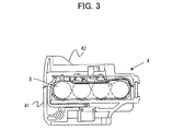
- Fig. 3 is a vertical cross-sectional view of the adapter according to the first embodiment of the invention.
- Fig. 4 is a bottom view of the adapter according to the first embodiment of the invention.
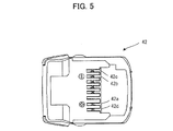
- Fig. 5 is a top view of the adapter according to the first embodiment of the invention.
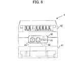
- Fig. 6 is a side view of the adapter according to the first embodiment of the invention.
- Fig. 7 is a flowchart of a transformation and switching control according to the first embodiment of the invention.
- Fig. 1 is an overall view of a battery pack, a power tool, and an adapter according to a first embodiment of the invention.
- Fig. 2 is a circuit diagram of the battery pack, the power tool, and the adapter according
- FIG. 8 is an explanation diagram showing a change of a current flowing into a motor at a boring operation.
- Fig. 9 is an explanation diagram showing a change of a current flowing into a motor at a screw driving operation.
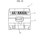
- Fig. 10 is a side view of an adapter according to a second embodiment of the invention.
- Fig. 11 is a flowchart of the voltage control according to the second embodiment of the invention.
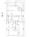
- Fig. 12 is an overall view of a battery pack according to a first modification of the invention.
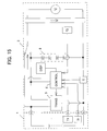
- Fig. 13 is a circuit diagram of the battery pack according to the first modification.
- Fig. 14 is an overall view of a power tool according to a second modification of the invention.
- Fig. 15 is a circuit diagram of the power tool according to the second modification.
- a battery pack 1, a power tool 2, and an adapter 3 according to a first embodiment of the invention will be described while referring to Figs. 1 through 7.
- a connecting portion of the battery pack 1 and a connecting portion of the power tool 2 have shapes that enable connection with each other, and the battery pack 1 can be connected directly with the power tool 2. In Fig. 1, however, the battery pack 1 and the power tool 2 are connected with each other via the adapter 3.
- the battery pack 1 includes an assembled battery 11 constructed by connecting four lithium unit cells 11a-11d in series.
- the battery pack 1 has a nominal voltage of 14.4V.
- the battery pack 1 includes a plus terminal 12 connected with a positive electrode of the assembled battery 11, a minus terminal 13 connected with a negative electrode of the assembled battery 11, a temperature detecting element 14 (referred as " T1" in Fig. 2) that outputs a signal in accordance with temperature of the assembled battery 11, an identification element 15 (referred as "I1" in Fig. 2) that outputs a signal in accordance with the number of the unit cells (four in the present embodiment), a temperature terminal 16 connected with the temperature detecting element 14, and an identification terminal 17 connected with the identification element 15.
- the power tool 2 includes a motor 21 and a trigger switch 22 connected with the motor 21 in series, and is so configured that, when the trigger switch 22 is turned on, electrical power is supplied from the battery pack 1 to the motor 21 via the adapter 3.
- the power tool 2 is a cordless power tool for a common rated voltage of 14.4V, for example, a driver drill, and functions normally when the battery pack 1 of the rated voltage of 14.4V is connected.
- the power tool 2 includes a plus terminal 23 connected with one end of the motor 21, a minus terminal 24 connected with another end of the motor 21, a temperature detecting element 25 (referred as “T2" in Fig. 2) that outputs a signal in accordance with temperature of the motor 21, an identification element 26 (referred as “T2” in Fig. 2) that outputs a signal in accordance with the rated voltage of the power tool 2 (the motor 21) (14.4V in the present embodiment), a temperature terminal 27 connected with the temperature detecting element 25, and an identification terminal 28 connected with the identification element 26.
- T2 temperature detecting element 25
- T2 identification element
- the adapter 3 includes a case 4 constructed by a lower case 41 and an upper case 42.
- the case 4 accommodates a normal terminal 4a (first output terminal), a transformer terminal 4b (second output terminal), a transformer circuit 5 (transforming unit), a controller 6 (control unit, storing unit, and measuring unit), a current detecting resistor 7 (referred as "C” in Fig. 2), a super capacitor 8 (capacitor), a switch 9 (control unit), and a protection IC 10 (referred as "P" in Fig. 2).
- the lower case 41 is provided with a lower plus terminal 41a connected with the plus terminal 12 of the battery pack 1, a lower minus terminal 41b connected with the minus terminal 13 of the battery pack 1, a temperature terminal 41c connected with the temperature terminal 16 of the battery pack 1, and an identification terminal 41d connected with the identification terminal 17 of the battery pack 1.
- the upper case 42 is provided with an upper plus terminal 42a connected with the plus terminal 23 of the power tool 2, an upper minus terminal 42b connected with the minus terminal 24 of the power tool 2, a temperature terminal 42c connected with the temperature terminal 27 of the power tool 2, and an identification terminal 42d connected with the identification terminal 28 of the power tool 2.
- a display unit 40 is provided near the connection between the lower case 41 and the upper case 42.
- the display unit 40 includes a "HIGH" button 43 (receiving unit) for increasing voltage to be outputted to the power tool 2, a "LOW” button 44 for decreasing voltage to be outputted to the power tool 2, and a full-charge informing unit 45 (charge-amount informing unit) that informs full charge of the super capacitor 8.
- the transformer circuit 5 is constructed from a DC/DC converter or a switching circuit.
- the transformer circuit 5 transforms a voltage supplied from the battery pack 1 via the lower plus terminal 41a, and outputs the transformed voltage to the transformer terminal 4b.
- the voltage outputted from the battery pack 1 to the lower plus terminal 41a is also outputted to the normal terminal 4a.
- the controller 6 obtains temperature of the battery pack 1 (the assembled battery 11) based on a temperature signal inputted from the temperature detecting element 14 of the battery pack 1 and, if the temperature of the battery pack 1 is higher than a predetermined value, breaks the circuit with the protection IC 10 to stop supply of electric power to the power tool 2 for protection of the battery pack 1.
- the controller 6 obtains temperature of the power tool 2 (the motor 21) based on a temperature signal inputted from the temperature detecting element 25 of the power tool 2 and, if the temperature of the power tool 2 (the motor 21) is higher than a predetermined value, breaks the circuit with the protection IC 10 to stop supply of electric power to the power tool 2 for protection of the motor 21.
- the controller 6 also breaks the circuit with the protection IC 10 to stop supply of electric power to the power tool 2 for preventing overcurrent.
- the super capacitor 8 is connected between the transformer terminal 4b (an output terminal of the transformer circuit 5) and the upper minus terminal 42b.
- the super capacitor 8 is constructed by connecting in series four electric double layer capacitors each having a capacity of 2 to 3V, and thus is capable of charging voltage outputted from the transformer circuit 5.
- the switch 9 is connected to the upper plus terminal 42a. By switching the switch 9, the upper plus terminal 42a is connected with either the normal terminal 4a or the transformer terminal 4b.
- the controller 6 of the present embodiment performs a transformation and switching control for controlling an amount of transformation by the transformer circuit 5 and for controlling output of transformed voltages.
- the controller 6 performs a control operation such that a voltage higher than the rated voltage of the power tool 2 (for example, 15.8V) (hereinafter referred to as “high voltage”) is outputted to the power tool 2 if the "HIGH” button 43 is on, and that a voltage lower than the rated voltage of the power tool 2 (for example, 13.0V) (hereinafter referred to as “low voltage”) is outputted to the power tool 2 if the "LOW" button 44 is on.
- a voltage higher than the rated voltage of the power tool 2 for example, 15.8V
- high voltage a voltage lower than the rated voltage of the power tool 2
- low voltage a voltage lower than the rated voltage of the power tool 2
- the controller 6 determines whether either the "HIGH” button 43 or the "LOW” button 44 is on (S101).
- the controller 6 controls the transformer circuit 5 to transform the voltage supplied from the battery pack 1 to the high voltage (S103), and switches the switch 9 such that the upper plus terminal 42a is connected with the transformer terminal 4b (S105) when the super capacitor 8 reaches a full charge with the high voltage (S104: Yes). With this operation, if the "HIGH” button 43 is on, the high voltage charged at the super capacitor 8 is outputted to the power tool 2.
- the controller 6 controls the transformer circuit 5 to transform the voltage supplied from the battery pack 1 to the low voltage (S106), and switches the switch 9 such that the upper plus terminal 42a is connected with the transformer terminal 4b (S105) when the super capacitor 8 reaches a full charge with the low voltage (S104: Yes). With this operation, if the "LOW" button 44 is on, the low voltage charged at the super capacitor 8 is outputted to the power tool 2.
- the circuit can deal with a high current at a high-load condition, without enlarging the scale of the transformer circuit 5.
- the controller 6 of the present embodiment stores both an ON continuation period in which an ON state of the "HIGH” button 43 continues and an ON number of times the "HIGH” button 43 is tuned on. If the ON continuation period exceeds a predetermined period or if the ON number of times exceeds a predetermined number of times, the controller 6 switches the switch 9 such that the upper plus terminal 42a is connected with the normal terminal 4a. This operation can prevent burnout of the motor 21 and shortening of lifetime of the battery pack 1 due to application of the high voltage for a long period or in high frequency.
- the controller 6 switches the switch 9 such that upper plus terminal 42a is connected with the transformer terminal 4b when the super capacitor 8 reaches full charge with the high voltage.
- the full-charge informing unit 45 informs the user of full charge of the super capacitor 8, thereby suppressing occurrence of such uncomfortable feeling.
- the user when a light-load operation is performed, by turning on the "LOW" button 44, the user can prevent that a voltage higher than necessary is supplied to the power tool 2, that the remaining amount of the battery pack 1 drops in a short period, and that the amount of operations per charge of the battery pack 1 becomes small considering the light-load operation Further, when the power charged in the capacitor 8 is run short, the power can be directly outputted from the battery pack 1 to the power tool 1 by switching the switch 9 and the capacitor 8 can be charged in this interval.
- a battery pack 1, a power tool 2, and an adapter 3 according to a second embodiment of the invention will be described while referring to Figs. 8 through 11.
- Like parts and components are designated by the same reference numerals as those shown in Figs. 1 through 7.
- a motor is basically driven by a specific rated voltage
- the motor can also be driven by voltages within a predetermined range around the rated voltage.
- a voltage supplied to a motor is constant regardless of magnitude of load.
- a load decreases and thus electric current flowing through the motor also decreases (see Fig. 8).
- electric current increases rapidly when time is 1.0 sec, which shows a state in which the trigger switch 22 is turned on. A starting current flows when the trigger switch 22 is turned on, and thereafter the electric current changes in accordance with load.
- the controller 6 of the present embodiment performs a voltage control in which voltages outputted to the power tool 2 are controlled based on load on the motor 21.
- the transformer circuit 5 and the switch 9 are controlled such that a voltage higher than a rated voltage of the power tool 2 (15.8V in the present embodiment) (hereinafter referred to as "high voltage”) is outputted to the power tool 2 if an electric current flowing through the motor 21 is larger than an upper limit (35A in the present embodiment) (a high voltage mode in Fig. 9).
- high voltage a voltage higher than a rated voltage of the power tool 2 (15.8V in the present embodiment)
- an electric current flowing through the motor 21 is larger than an upper limit (35A in the present embodiment) (a high voltage mode in Fig. 9).
- the transformer circuit 5 and the switch 9 are controlled such that a voltage lower than the rated voltage of the power tool 2 (13.0V in the present embodiment) (hereinafter referred to as "low voltage") is outputted to the power tool 2 if the electric current flowing through the motor 21 is smaller than an lower limit (10A in the present embodiment) (a low voltage mode in Fig. 9).
- Fig. 9 indicates changes in electric current during a screw driving operation in which the power tool 2 (driver drill) is used.
- Electric current increases rapidly when time is 1.0 sec, which shows a state in which the trigger switch 22 is turned on.
- the starting current of the motor (approximately 60A) flows when the trigger switch 22 is turned on, and thereafter the electric current changes in accordance with load.
- the power tool 2 operates in the high voltage mode if the electric current exceeds 35A, operates in the low voltage mode if the electric current falls below 10A, and operates in a normal mode if the electric current is between 10A and 35A. Further, determination of electric current described later is not performed within a predetermined period, 0.4 sec for example, after a startup of the motor, so that starting current at the startup of the motor does not affect mode switching.
- a charge-amount display unit 140 (charge-amount informing unit) is provided near the connection between the lower case 41 and the upper case 42 instead of the display unit 40.
- the charge-amount display unit 140 displays a charged amount of the super capacitor 8.
- FIG. 11 A voltage control performed by the controller 6 will be described while referring to the flowchart of Fig. 11.
- the flowchart of Fig. 11 is started when both of the battery pack 1 and the power tool 2 are connected with the adapter 3.
- the inputted voltage is so low that a sufficient torque may not be outputted.
- the controller 6 obtains the nominal voltage of the battery pack 1 from the discrimination element 15 of the battery pack 1, and obtains the rated voltage of the power tool 2 from the discrimination element 26 of the power tool 2 (S201), and then determines whether both of the nominal voltage and the rated voltage match (S202).
- the controller 6 controls the transformer circuit 5 to transform voltage supplied from the battery pack 1 into the rated voltage (S203), and then switches the switch 9 such that the upper plus terminal 42a is connected with the transformer terminal 4b (S204). With this operation, the rated voltage can be supplied to the power tool 2 even when the nominal voltage and the rated voltage do not match.
- the voltage of the battery pack 1 can be used without transformation. However, in order to obtain an appropriate output, voltage 14.4V of the battery pack 1 is raised to 18.0V by the transformer circuit 5. Conversely, in a case where the nominal voltage of the battery pack 1 is 18.0V and the rated voltage of the power tool 2 is 14.4V, there is a possibility that the power tool 2 (the motor 21) is damaged if a voltage higher than the rated voltage of the power tool 2 is applied for a long period. Hence, the voltage 18.0V of the battery pack 1 is lowered to 14.4V by the transformer circuit 5, and is then outputted.
- the controller 6 determines whether the electric current flowing through the motor 21 is larger than the upper limit (S205). Specifically, the controller 6 calculates an average value of electric current values once every 0.1 sec, and determines whether the average value is larger than 35A.
- the controller 6 controls the transformer circuit 5 to transform the voltage supplied from the battery pack 1 into a high voltage (15.8V) (S206), and then switches the switch 9 such that the upper plus terminal 42a is connected with the transformer terminal 4b (S207) (the high voltage mode in Fig. 9).
- the controller 6 stores a duration of the high voltage and the number of times of switching. If the duration exceeds a predetermined period and if the number of times of switching exceeds a predetermined number, the controller 6 switches the switch 9 such that the upper plus terminal 42a is connected with the normal terminal 4a. This can prevent burnout of the motor 21 and shortening of lifetime of the battery pack 1 due to application of the high voltage for a long period or in high frequency.
- the controller 6 determines whether the electric current is smaller than the lower limit (S208).
- the controller 6 controls the transformer circuit 5 to transform the voltage supplied from the battery pack 1 into a low voltage (13.0V) (S209), and then switches the switch 9 such that the upper plus terminal 42a is connected with the transformer terminal 4b (S207) (the low voltage mode in Fig. 9).
- the controller 6 obtains an average value of electric current values once every 3.0 sec, and determines that it is in a low load condition if the number of times the obtained average value becomes smaller than 10A is larger than or equal to ten times.
- the controller 6 may determine that it is in a low load condition if the average value becomes smaller than 10A once. With this criterion, a control can be performed more accurately in accordance with kinds of operations.
- the controller 6 switches the switch 9 such that the upper plus terminal 42a is connected with the normal terminal 4a (S210). Note that, if the switch 9 is switched to the transformer terminal 4b in S204, a voltage is outputted from the transformer terminal 4b even if a "No" determination is made in S208.
- a voltage control is performed in such a manner that a voltage outputted to the power tool 2 is controlled based on a load on the motor 21.
- voltages suitable for kinds of operations can be supplied to the motor 21.
- the power tool 2 can be operated temporarily with high power.
- the voltage of the battery pack 1 is transformed into the low voltage and outputted to the power tool 2. This can prevent that a voltage higher than necessary is supplied to the power tool 2 during a light-load operation such as a final phase of a boring operation and a driving operation of a small screw.
- the controller 6 switches the switch 9 such that the upper plus terminal 42a is connected with the normal terminal 4a. This can prevent burnout of the motor 21 and shortening of lifetime of the battery pack 1 due to application of the high voltage for a long period or in high frequency.
- the amount of electric power charged at the super capacitor 8 is displayed so that the charged amount of the capacitor can be recognized. Hence, the workability can be improved.
- the normal terminal 4a, the transformer terminal 4b, the transformer circuit 5, the controller 6, the current detecting resistor 7, the super capacitor 8, the switch 9, the protection IC 10, and the display unit 40 are provided at the adapter 3.
- the adapter 3 it is not necessary that all of these components be provided at the adapter 3, but it is only necessary that these components be provided within a power tool system including the battery pack 1, the power tool 2, and the adapter 3.
- the adapter 3 is not necessary if the connecting portion of the battery pack 1 and the connecting portion of the power tool 2 have shapes that enable connection with each other, or if the nominal voltage of the battery pack 1 and the rated voltage of the power tool 2 are identical. In such cases, it is only necessary that the normal terminal 4a, the transformer terminal 4b, the transformer circuit 5, the controller 6, the current detecting resistor 7, the super capacitor 8, the switch 9, the protection IC 10, and the display unit 40 (charge-amount display unit 140) be provided within a power tool system including the battery pack 1 and the power tool 2.
- the configurations of the adapter 3 may be provided in the battery pack 1 as shown in Figs. 12 and 13.
- the transformer circuit 5, the controller 6, the super capacitor 8, the switch 9, and the display unit 40 etc. are provided in the battery pack 1 in addition to the assembled battery 11 and the temperature detecting element 14.
- the identification element 15 is not provided in the battery pack 1 since there is no need for informing the adapter 3 of the information with respect to the battery pack 1.
- the configurations of the adapter 3 may be provided in the power tool 2 as shown in Figs. 14 and 15.
- the transformer circuit 5, the controller 6, the super capacitor 8, the switch 9, and the display unit 40 etc. are provided in the power tool 2 in addition to the motor 21, the trigger switch 22, the temperature detecting element 25, and the identification element 26.
- controller 6 may control the motor 21.
- the controller 6 controls a plurality of switching elements (for example, six FETs) connected to the motor 21.
- the protection IC 10 may be provided in not the adapter 3 but the battery pack 1 or the power tool 2 since the protection IC 10 only has to protect the battery pack 1 or the power tool 2. It is preferable that the protection IC 10 that cuts off the current pathway when detecting the overdischarge or the overcharge is provided in the battery pack 1 when detecting the voltage of each of the cells 11a-11d.
- the controller 6 may detect the voltage of each of the cells 11a-11d to protect the overdischarge, the overcharge, and the overcurrent. In this case, the controller 6 cuts off a cut-off member (for example, a switching element such as an FET) disposed on the current pathway when detecting an abnormal condition.
- a cut-off member for example, a switching element such as an FET
- the adapter 3 may be so configured that the transformer voltage is changeable depending on the number of times the "HIGH” button 43 or the "LOW” button 44 is pressed. In this case, an output voltage more suitable for the operation condition of the power tool 2 can be obtained.
- the switch 9 may be switched manually, not automatically, so that the switch 9 can be switched arbitrarily depending on the operation.
- a voltage of 14.4V may be outputted without performing the above-mentioned voltage increase control.
- the controller 6 may also automatically obtain the nominal voltages of the battery pack 1 and the power tool 2 in accordance with signals of the identification element 15 of the battery pack 1 and the identification element 26 of the power tool 2, and control the transformer circuit 5.
- controller 6 may automatically control a transforming operation of the transformer circuit 5 in accordance with signals from the temperature detecting element 14 of the battery pack 1 and from the temperature detecting element 25 of the power tool 2.
- the controller 6 may stop charging at the super capacitor 8 even when the "HIGH" button 43 is pressed, and may control the full-charge informing unit 45 of the display unit 40 to blink so as to inform the user of a high-temperature standby state. In this way, reduction in lifetime of the battery pack 1 or the power tool 2 due to high temperature can be suppressed.
- the load may be determined based on the signal from the temperature detecting elements 14 and 25 or the rotating number of the motor 21etc. although the load is detected based on the current flowing into the motor 21 in the second embodiment.
- the super capacitor 8 may be charged with a power supplied from a power source, such as a solar battery, other than the battery pack 1.
- a power source such as a solar battery
Landscapes
- Engineering & Computer Science (AREA)
- Manufacturing & Machinery (AREA)
- Chemical & Material Sciences (AREA)
- Chemical Kinetics & Catalysis (AREA)
- Electrochemistry (AREA)
- General Chemical & Material Sciences (AREA)
- Power Engineering (AREA)
- Mechanical Engineering (AREA)
- Charge And Discharge Circuits For Batteries Or The Like (AREA)
- Secondary Cells (AREA)
- Battery Mounting, Suspending (AREA)
- Portable Power Tools In General (AREA)
Abstract
La présente invention concerne un système d'outil électrique (2), comprenant : une batterie secondaire (1); un condensateur (8), configuré pour alimenter en électricité un moteur (21); et une unité de transformation (5), configurée pour amplifier la tension de batterie de la batterie secondaire jusqu'à une tension de charge, le condensateur étant chargé avec la tension de charge.
Applications Claiming Priority (4)
| Application Number | Priority Date | Filing Date | Title |
|---|---|---|---|
| JP2011038776 | 2011-02-24 | ||
| JP2011-038776 | 2011-02-24 | ||
| JP2011038883 | 2011-02-24 | ||
| JP2011-038883 | 2011-02-24 |
Publications (1)
| Publication Number | Publication Date |
|---|---|
| WO2012114749A1 true WO2012114749A1 (fr) | 2012-08-30 |
Family
ID=45876850
Family Applications (1)
| Application Number | Title | Priority Date | Filing Date |
|---|---|---|---|
| PCT/JP2012/001228 Ceased WO2012114749A1 (fr) | 2011-02-24 | 2012-02-23 | Bloc de batterie secondaire, et outil électrique |
Country Status (2)
| Country | Link |
|---|---|
| JP (1) | JP2012191838A (fr) |
| WO (1) | WO2012114749A1 (fr) |
Cited By (13)
| Publication number | Priority date | Publication date | Assignee | Title |
|---|---|---|---|---|
| CN103943798A (zh) * | 2014-05-09 | 2014-07-23 | 廖建勋 | 7号电池转换为6f22电池的转换支架 |
| WO2016116167A1 (fr) * | 2015-01-23 | 2016-07-28 | Vega Grieshaber Kg | Bloc-batterie destiné à alimenter en courant un appareil de terrain |
| WO2018079722A1 (fr) * | 2016-10-31 | 2018-05-03 | 日立工機株式会社 | Bloc-batterie, appareil électrique utilisant un bloc-batterie, et système d'appareil électrique |
| GB2566577A (en) * | 2017-09-13 | 2019-03-20 | Snap On Tools Corp | Power supply continuity system |
| FR3075510A1 (fr) * | 2017-12-19 | 2019-06-21 | Etablissements Georges Renault | Outil electromecanique portatif comportant un moteur alimente par un ensemble de condensateurs charges par au moins une batterie |
| CN111030218A (zh) * | 2019-12-13 | 2020-04-17 | 张家港华捷电子有限公司 | 电池包适配器 |
| EP3663051A1 (fr) * | 2018-11-27 | 2020-06-10 | Panasonic Intellectual Property Management Co., Ltd. | Unité de batterie et système d'outil électrique |
| DE102019220592A1 (de) * | 2019-12-27 | 2021-07-01 | Robert Bosch Gmbh | Verfahren zu einer Interaktion mit zumindest einem Bediener eines akkubetriebenen Bearbeitungsgeräts sowie System zur Durchführung des Verfahrens |
| US11385089B2 (en) | 2018-07-20 | 2022-07-12 | Vega Grieshaber Kg | Battery-operated field device with time transmission |
| WO2023041218A1 (fr) * | 2021-09-14 | 2023-03-23 | Robert Bosch Gmbh | Module d'interface pour commander un appareil consommateur d'électricité avec au moins un dispositif de stockage d'énergie échangeable et procédé pour commander l'appareil consommateur d'électricité au moyen du module d'interface |
| CN116723913A (zh) * | 2021-03-31 | 2023-09-08 | 工机控股株式会社 | 电动机器 |
| US11946267B2 (en) | 2016-12-29 | 2024-04-02 | Max Co., Ltd. | Binding machine |
| US12061943B2 (en) | 2018-07-20 | 2024-08-13 | Vega Grieshaber Kg | Measuring device with near field interaction device |
Families Citing this family (10)
| Publication number | Priority date | Publication date | Assignee | Title |
|---|---|---|---|---|
| JP2014148009A (ja) * | 2013-02-01 | 2014-08-21 | Makita Corp | 電動機械器具、及びその本体 |
| JP6026908B2 (ja) * | 2013-02-07 | 2016-11-16 | 株式会社マキタ | 電動機械器具及びバッテリパック |
| JP2014172163A (ja) | 2013-03-13 | 2014-09-22 | Panasonic Corp | 電動工具 |
| JP2014176919A (ja) * | 2013-03-14 | 2014-09-25 | Hitachi Koki Co Ltd | 電動工具 |
| JP6737709B2 (ja) * | 2014-05-18 | 2020-08-12 | ブラック アンド デッカー インクBlack & Decker Inc. | 電動工具システム |
| SE543362C2 (en) * | 2015-10-13 | 2020-12-15 | Atlas Copco Ind Technique Ab | A method of driving a motor of a power tool, a power supply system and a power tool |
| JP2018073663A (ja) * | 2016-10-31 | 2018-05-10 | 日立工機株式会社 | 電池パック |
| GB2562064A (en) * | 2017-05-02 | 2018-11-07 | Zapgo Ltd | Supercapacitor device |
| CN207559587U (zh) * | 2017-06-15 | 2018-06-29 | 浙江白马实业有限公司 | 一种园林工具的电压向下兼容控制器 |
| JP6981841B2 (ja) * | 2017-10-18 | 2021-12-17 | 株式会社マキタ | 電動作業機 |
Citations (7)
| Publication number | Priority date | Publication date | Assignee | Title |
|---|---|---|---|---|
| US20030214269A1 (en) * | 2002-05-13 | 2003-11-20 | Lih-Ren Shiue | High current pulse generator |
| US20060108980A1 (en) * | 2002-12-04 | 2006-05-25 | Shinichi Ookubo | Cordless power tool |
| US20060133007A1 (en) * | 2004-12-07 | 2006-06-22 | Lih-Ren Shiue | Power supply apparatus and power supply method |
| JP2008178278A (ja) | 2006-09-19 | 2008-07-31 | Hitachi Koki Co Ltd | アダプタ、電池パックとアダプタの組み合わせ、及びそれらを備えた電動工具 |
| US20090096416A1 (en) * | 2005-12-06 | 2009-04-16 | Toyota Jidosha Kabushiki Kaisha | Charging Device, Electric Vehicle Equipped With the Charging Device and Charging Control Method |
| US20090108806A1 (en) * | 2006-09-19 | 2009-04-30 | Nobuhiro Takano | Adaptor, assembly of battery pack and adaptor, and electric tool with the same |
| US20090289589A1 (en) * | 2008-05-21 | 2009-11-26 | Honda Motor Co., Ltd. | Power supply system |
Family Cites Families (2)
| Publication number | Priority date | Publication date | Assignee | Title |
|---|---|---|---|---|
| JP2003048177A (ja) * | 2001-08-03 | 2003-02-18 | Nec Tokin Corp | 携帯型電動工具 |
| JP4682766B2 (ja) * | 2005-09-20 | 2011-05-11 | トヨタ自動車株式会社 | 車両用電源装置 |
-
2012
- 2012-02-23 JP JP2012037341A patent/JP2012191838A/ja active Pending
- 2012-02-23 WO PCT/JP2012/001228 patent/WO2012114749A1/fr not_active Ceased
Patent Citations (7)
| Publication number | Priority date | Publication date | Assignee | Title |
|---|---|---|---|---|
| US20030214269A1 (en) * | 2002-05-13 | 2003-11-20 | Lih-Ren Shiue | High current pulse generator |
| US20060108980A1 (en) * | 2002-12-04 | 2006-05-25 | Shinichi Ookubo | Cordless power tool |
| US20060133007A1 (en) * | 2004-12-07 | 2006-06-22 | Lih-Ren Shiue | Power supply apparatus and power supply method |
| US20090096416A1 (en) * | 2005-12-06 | 2009-04-16 | Toyota Jidosha Kabushiki Kaisha | Charging Device, Electric Vehicle Equipped With the Charging Device and Charging Control Method |
| JP2008178278A (ja) | 2006-09-19 | 2008-07-31 | Hitachi Koki Co Ltd | アダプタ、電池パックとアダプタの組み合わせ、及びそれらを備えた電動工具 |
| US20090108806A1 (en) * | 2006-09-19 | 2009-04-30 | Nobuhiro Takano | Adaptor, assembly of battery pack and adaptor, and electric tool with the same |
| US20090289589A1 (en) * | 2008-05-21 | 2009-11-26 | Honda Motor Co., Ltd. | Power supply system |
Cited By (19)
| Publication number | Priority date | Publication date | Assignee | Title |
|---|---|---|---|---|
| CN103943798A (zh) * | 2014-05-09 | 2014-07-23 | 廖建勋 | 7号电池转换为6f22电池的转换支架 |
| WO2016116167A1 (fr) * | 2015-01-23 | 2016-07-28 | Vega Grieshaber Kg | Bloc-batterie destiné à alimenter en courant un appareil de terrain |
| WO2018079722A1 (fr) * | 2016-10-31 | 2018-05-03 | 日立工機株式会社 | Bloc-batterie, appareil électrique utilisant un bloc-batterie, et système d'appareil électrique |
| US11824169B2 (en) | 2016-10-31 | 2023-11-21 | Koki Holdings Co., Ltd. | Battery pack, electrical device using battery pack, and electrical device system |
| JPWO2018079722A1 (ja) * | 2016-10-31 | 2019-09-19 | 工機ホールディングス株式会社 | 電池パック及び電池パックを用いた電気機器、電気機器システム |
| US11946267B2 (en) | 2016-12-29 | 2024-04-02 | Max Co., Ltd. | Binding machine |
| US11296541B2 (en) | 2017-09-13 | 2022-04-05 | Snap-On Incorporated | Power supply continuity system |
| GB2566577B (en) * | 2017-09-13 | 2022-05-11 | Snap On Tools Corp | Power supply continuity system |
| GB2566577A (en) * | 2017-09-13 | 2019-03-20 | Snap On Tools Corp | Power supply continuity system |
| FR3075510A1 (fr) * | 2017-12-19 | 2019-06-21 | Etablissements Georges Renault | Outil electromecanique portatif comportant un moteur alimente par un ensemble de condensateurs charges par au moins une batterie |
| US11385089B2 (en) | 2018-07-20 | 2022-07-12 | Vega Grieshaber Kg | Battery-operated field device with time transmission |
| US12061943B2 (en) | 2018-07-20 | 2024-08-13 | Vega Grieshaber Kg | Measuring device with near field interaction device |
| EP3663051A1 (fr) * | 2018-11-27 | 2020-06-10 | Panasonic Intellectual Property Management Co., Ltd. | Unité de batterie et système d'outil électrique |
| CN111030218A (zh) * | 2019-12-13 | 2020-04-17 | 张家港华捷电子有限公司 | 电池包适配器 |
| DE102019220592A1 (de) * | 2019-12-27 | 2021-07-01 | Robert Bosch Gmbh | Verfahren zu einer Interaktion mit zumindest einem Bediener eines akkubetriebenen Bearbeitungsgeräts sowie System zur Durchführung des Verfahrens |
| US12394992B2 (en) | 2019-12-27 | 2025-08-19 | Robert Bosch Gmbh | Method for interacting with at least one user of a rechargeable-battery-operated machining tool, and system for carrying out the method |
| CN116723913A (zh) * | 2021-03-31 | 2023-09-08 | 工机控股株式会社 | 电动机器 |
| CN116723913B (zh) * | 2021-03-31 | 2025-11-18 | 工机控股株式会社 | 电动机器 |
| WO2023041218A1 (fr) * | 2021-09-14 | 2023-03-23 | Robert Bosch Gmbh | Module d'interface pour commander un appareil consommateur d'électricité avec au moins un dispositif de stockage d'énergie échangeable et procédé pour commander l'appareil consommateur d'électricité au moyen du module d'interface |
Also Published As
| Publication number | Publication date |
|---|---|
| JP2012191838A (ja) | 2012-10-04 |
Similar Documents
| Publication | Publication Date | Title |
|---|---|---|
| JP2012191838A (ja) | 電池パック、電動工具、電池パックと電動工具とを接続するアダプタ、及び、電動工具システム | |
| US10320214B2 (en) | Power tool | |
| JP4660523B2 (ja) | 電池セルの表面温度で充電制御する充電システム | |
| JP5275176B2 (ja) | 電池パックおよびその機能停止方法 | |
| US9768625B2 (en) | Battery pack, and method for controlling the same | |
| EP2595270B1 (fr) | Outil électrique utilisant une batterie d'accumulateurs comme source d'alimentation électrique, ainsi qu'adaptateur correspondant | |
| CN101154820B (zh) | 适配器、电池组与适配器的组合、及具该组合的电动工具 | |
| US8384349B2 (en) | Monitoring system for electric power tool, battery pack for electric power tool, and battery charger for electric power tool | |
| US8269458B2 (en) | Shared control of thermistor and dual purpose thermistor line | |
| US5861730A (en) | Battery charging apparatus | |
| JP3904489B2 (ja) | 充電制御回路、充電器、電源回路、及び情報処理装置、並びに電池パック | |
| JP5361353B2 (ja) | 二次電池の充電制御方法および充電制御装置 | |
| JP2008236878A (ja) | 充電装置 | |
| KR20060047861A (ko) | 전원 장치 및 그 전원 장치에 이용되는 제어 방법 | |
| AU2007216856A1 (en) | Adaptor, assembly of battery pack and adaptor, and electric tool with the same | |
| US20100237832A1 (en) | Charging method and charging system | |
| WO2014103306A2 (fr) | Dispositif d'alimentation électrique | |
| US20130257359A1 (en) | Charger | |
| US20040196004A1 (en) | Power source circuit for cell and cell pack | |
| EP4266539A1 (fr) | Dispositif d'alimentation électrique | |
| WO2014087675A2 (fr) | Dispositif de charge | |
| JP4821691B2 (ja) | 二次電池パック | |
| JP2012151921A (ja) | インバータ装置及びそれを備えた電動工具 | |
| JP2009089499A (ja) | 充電式電器機器 | |
| JP2006304548A (ja) | 充電制御装置 |
Legal Events
| Date | Code | Title | Description |
|---|---|---|---|
| 121 | Ep: the epo has been informed by wipo that ep was designated in this application |
Ref document number: 12710366 Country of ref document: EP Kind code of ref document: A1 |
|
| NENP | Non-entry into the national phase |
Ref country code: DE |
|
| 122 | Ep: pct application non-entry in european phase |
Ref document number: 12710366 Country of ref document: EP Kind code of ref document: A1 |