WO2012114751A1 - Machine à laver à tambour - Google Patents
Machine à laver à tambour Download PDFInfo
- Publication number
- WO2012114751A1 WO2012114751A1 PCT/JP2012/001232 JP2012001232W WO2012114751A1 WO 2012114751 A1 WO2012114751 A1 WO 2012114751A1 JP 2012001232 W JP2012001232 W JP 2012001232W WO 2012114751 A1 WO2012114751 A1 WO 2012114751A1
- Authority
- WO
- WIPO (PCT)
- Prior art keywords
- water tank
- vibration
- damper
- drum
- washing machine
- Prior art date
- Legal status (The legal status is an assumption and is not a legal conclusion. Google has not performed a legal analysis and makes no representation as to the accuracy of the status listed.)
- Ceased
Links
Images


Classifications
-
- D—TEXTILES; PAPER
- D06—TREATMENT OF TEXTILES OR THE LIKE; LAUNDERING; FLEXIBLE MATERIALS NOT OTHERWISE PROVIDED FOR
- D06F—LAUNDERING, DRYING, IRONING, PRESSING OR FOLDING TEXTILE ARTICLES
- D06F37/00—Details specific to washing machines covered by groups D06F21/00 - D06F25/00
- D06F37/20—Mountings, e.g. resilient mountings, for the rotary receptacle, motor, tub or casing; Preventing or damping vibrations
- D06F37/22—Mountings, e.g. resilient mountings, for the rotary receptacle, motor, tub or casing; Preventing or damping vibrations in machines with a receptacle rotating or oscillating about a horizontal axis
-
- D—TEXTILES; PAPER
- D06—TREATMENT OF TEXTILES OR THE LIKE; LAUNDERING; FLEXIBLE MATERIALS NOT OTHERWISE PROVIDED FOR
- D06F—LAUNDERING, DRYING, IRONING, PRESSING OR FOLDING TEXTILE ARTICLES
- D06F34/00—Details of control systems for washing machines, washer-dryers or laundry dryers
- D06F34/14—Arrangements for detecting or measuring specific parameters
- D06F34/16—Imbalance
-
- D—TEXTILES; PAPER
- D06—TREATMENT OF TEXTILES OR THE LIKE; LAUNDERING; FLEXIBLE MATERIALS NOT OTHERWISE PROVIDED FOR
- D06F—LAUNDERING, DRYING, IRONING, PRESSING OR FOLDING TEXTILE ARTICLES
- D06F2103/00—Parameters monitored or detected for the control of domestic laundry washing machines, washer-dryers or laundry dryers
- D06F2103/26—Imbalance; Noise level
Definitions
- This invention relates to the drum type washing machine which controls the vibration of the whole aquarium.
- FIG. 6 shows a configuration diagram of a conventional drum-type washing machine described in Patent Document 1.
- the drum 101 that accommodates and rotates the laundry is rotatably disposed in the water tank 103.
- a motor 105 that rotates the drum 101 is provided at the bottom of the water tank 103.
- a lid 108 is provided at the opening of the drum 101 so as to be freely opened and closed.
- a spring body 110 is provided between the water tank 103 and the housing 109. The posture of the water tank 103 is maintained by the spring body 110. Further, the water tank 103 is supported by a vibration isolating damper 111 so that the vibration of the water tank 103 is not transmitted to the housing 109 during the dehydrating operation.
- a seal packing 107 is provided between the laundry input port on the front surface of the water tank 103 and the housing 109. Yes.
- a vibration detection device 106 using an acceleration sensor is disposed on the upper front side of the water tank 103.
- the unbalance determination unit 113 determines an unbalanced state (unstable state) in the drum 101 in accordance with the output of the vibration detection device 106.
- the control unit 116 controls the operation of the motor 5 to control the vibration.
- FIG. 7 is a longitudinal sectional view of a conventional drum-type washing machine described in Patent Document 2.
- FIG. 8 is an internal front view of the main part of the drum type washing machine.
- the drum 121 included in the water tank 120 is rotationally driven with a horizontal shaft 122 attached to the drum 121 as a rotation center axis.
- the water tank 120 is suspended from the upper part of the main body 118 by two pairs of spring bodies 126.
- the water tank 120 is supported by a pair of vibration damping dampers 127 from the bottom of the main body 118 for vibration isolation.
- a weight 128 for suppressing vibration of the water tank 120 is provided at the front of the water tank 120.
- the water tank 120 is provided with a vibration detection device 130 that detects vibration of the water tank 120 using an acceleration sensor. As shown in FIG.
- the vibration detection device 130 is provided at a position symmetrical to the motor 124 disposed in the vicinity of the lower corner of the main body 118 around the central axis 134 of the water tank 120.
- the vibration detection device 130 detects the maximum vibration value of the water tank 120 that vibrates around the heavy motor 124 as the center of revolution.
- the vibration on the front side of the water tank becomes larger than the vibration on the rear side of the water tank.
- the seal packing provided between the front side of the water tank and the housing is generally made of a rubber material for vibration isolation.
- the vibration value of the water tank is reduced because the vibration of the aquarium is attenuated by the vibration damping damper. Therefore, even if it is attempted to detect vibration components in a plurality of directions with the acceleration sensor of the vibration detection device disposed on the upper front side of the water tank, the determination method becomes complicated. Thus, there also existed a subject that an unbalanced state was difficult to determine.
- the present invention solves the above-described conventional problems, and makes an accurate imbalance determination based on the arrangement balance of the support damper and the vibration damper, the position and direction of the vibration damper, the position of the acceleration sensor, and the like.
- the object is to provide a low-vibration drum-type washing machine.
- the drum type washing machine of the present invention includes a rotating drum having a substantially horizontal rotating shaft, A water tank containing the rotating drum; A motor for rotating the rotating drum; A washing machine housing elastically supported by a plurality of dampers from the lower side of the water tank; A vibration detection unit for detecting the vibration of the aquarium,
- the plurality of dampers include a first damper and a second damper, The second damper is provided such that a compressive force received from a rotating drum that rotates in the forward direction is greater than that of the first damper.
- the second damper and the vibration detector are disposed on the back side of the center of gravity in the front-rear direction of the water tank,
- the first damper is disposed on the front side of the second damper.
- drum type washing machine of the present invention accurate imbalance determination is performed and low vibration is realized.
- FIG. 3 The longitudinal cross-sectional view of the drum type washing machine in Embodiment 1 of this invention
- FIG. 3 is a circuit diagram showing a part of the configuration related to the control device of the drum type washing machine of FIG. Configuration diagram of a conventional drum-type washing machine Vertical section of another conventional drum-type washing machine
- a rotating drum having a substantially horizontal rotating shaft; A water tank containing the rotating drum; A motor for rotating the rotating drum; A washing machine housing elastically supported by a plurality of dampers from the lower side of the water tank; A vibration detection unit for detecting the vibration of the aquarium,
- the plurality of dampers include a first damper and a second damper, The second damper is provided such that a compressive force received from a rotating drum that rotates in the forward direction is greater than that of the first damper.
- the second damper and the vibration detector are disposed on the back side of the center of gravity in the front-rear direction of the water tank,
- the first damper provides a drum-type washing machine disposed on the front side of the second damper.
- the vibration detection unit and the second damper are disposed on a substantially vertical plane that is substantially the same as the center of gravity of the motor in the front-rear direction. Provide a machine.
- the vibration detection unit is a drum according to the first aspect or the second aspect, wherein the vibration detection unit is disposed at a substantially symmetric position with respect to the rotation shaft of the rotation drum.
- the vibration detection unit is disposed at a substantially symmetric position with respect to the rotation shaft of the rotation drum.
- the fourth aspect of the present invention further comprising a spring for suspending the water tub from the washing machine housing,
- the said spring provides the drum type washing machine as described in a 1st aspect or a 2nd aspect arrange
- FIG. 1 is a longitudinal sectional view of a drum-type washing machine according to Embodiment 1 of the present invention.
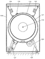
- FIG. 2 is a front view of the inside of the drum type washing machine as viewed from the front.
- the rotating drum 17 formed in a bottomed cylindrical shape is rotatably disposed in the water tank 19.
- the water tank 19 moves the rotating drum 17 inward.
- a large number of water passage holes 18 are provided on the entire outer peripheral wall of the rotary drum 17.
- a rotation axis (rotation center axis) 20 exists at the rotation center of the rotary drum 17.
- the rotary shaft 20 is substantially horizontal, and the axial center direction of the rotary drum 17 is also substantially horizontal.
- a drum pulley 28 is connected to the back surface of the water tank 19 located on the rotating shaft 20.
- the drum pulley 28 is connected to the motor 21 via a belt 29.
- the motor 21 is connected to the rotating drum 17 by a belt 29 and a drum pulley 28.
- the motor 21 rotationally drives the rotary drum 17 in the forward direction or the reverse direction.
- On the inner wall surface of the rotating drum 17, a plurality of protruding plates 22 are provided for stirring the laundry.
- Rotating drum 17, water tank 19, motor 21, drum pulley 28 and the like constitute a water tank unit 37.
- the weight of the water tub 19 is supported by dampers 25 and 26 for damping vibration isolation that are attached to the base portion 24 of the washing machine housing 23.
- a spring body 27 is provided between the upper surface of the washing machine housing 23 and the upper part of the water tub 19.
- the water tank 19 is supported by a spring body 27 so as to swing freely and elastically. That is, the washing machine housing 23 elastically supports the water tub 19 from the lower side by the plurality of dampers 25 and 26.
- the dampers 25 and 26 include a pair of support dampers 25 (first dampers) arranged symmetrically when viewed from the front side, and a single vibration damper 26 (second damper). Damper).
- the support damper 25 supports the water tank 19 and suppresses vibration of the water tank 19. As shown in FIG. 1, the support damper 25 is disposed on the front side of the center of gravity position G in the front-rear direction of the water tank unit 37.
- Anti-vibration damper 26 suppresses vibration of water tank 19 in particular. As shown in FIG. 1, the anti-vibration damper 26 is disposed on the back side of the gravity center position G. That is, the support damper 25 is disposed on the front side of the vibration damping damper 26. The water tank unit 37 is supported in a well-balanced manner by the support damper 25 and the vibration damping damper 26, and the damping vibration is performed.
- the vibration damper 26 is provided so that the compressive force received from the rotating drum 17 rotating in the normal rotation direction (left rotation) A is larger than that of the two support dampers 25. Yes.
- the anti-vibration damper 26 has a normal rotation direction with respect to a straight line connecting the housing support 35 and the center position C of the water tank 19 as viewed from the front. It is provided on the upstream side of A so as to be inclined at an angle ⁇ .
- the vibration damping damper 26 should just be arrange
- the anti-vibration damper 26 is provided so that the inclination angle with respect to the bottom surface of the washing machine casing 23 extending in the horizontal direction is smaller than that of the support damper 25. As a result, the vibration damping damper 26 exhibits a greater damping effect particularly with respect to vibration in the horizontal direction (left-right direction in FIG. 2).
- damping force of the support damper 25 and the damping force of the vibration damping damper 26 may be the same.
- damping force of the vibration damping damper 26 may be slightly weaker than the damping force of the support damper 25.
- a seal packing 38 formed of a rubber material or the like is connected between the front side of the water tub 19 and the washing machine housing 23.
- the opening 39 of the washing machine housing 23 is covered with a lid 30 so as to be freely opened and closed.
- the lid 30 By opening the lid 30, the laundry is put into the rotary drum 17 through the opening 39, and the laundry is taken out from the rotary drum 17.
- a control device 31 is provided above the water tank 19.
- the control device 31 includes a microcomputer that controls a series of steps such as washing, rinsing, and dehydration.
- the control device 31 performs signal transmission with an input setting unit 32 disposed above the lid body 30 and an acceleration sensor (vibration detection unit) 34 disposed above the water tank 19.
- the control device 31 controls the rotation of the motor 21 and the like.
- Acceleration sensor 34 detects acceleration and vibration not only in one direction but also in multiple axes (two or three axes) such as front and rear, left and right, and top and bottom. Since the actual vibration of the aquarium unit 37 is not necessarily limited to one direction, the movement of the aquarium unit 37 is detected with high accuracy by using the multi-axis acceleration sensor 34.
- the lid 30 is opened, the laundry is put into the rotating drum 17, and the operation is started.
- the rotary drum 17 is driven to rotate at a low speed by the motor 21.
- the rotary drum 17 is driven to rotate, the laundry in the rotary drum 17 is lifted and dropped onto the water surface in the rotary drum 17.
- the washing process proceeds.
- the washing water in the water tank 19 is drained and intermediate dehydration is performed.
- a rinsing step is performed. Also in the rinsing process, the same operation as the washing process is performed.
- the laundry is centrifugally dehydrated by rotating the rotary drum 17 at a high speed.
- the spring body 27 and the like support the water tank 19 in a swingable manner, so that vibration is prevented from being transmitted to the washing machine housing 23.
- the water tub 19 vibrates abnormally when the amount of the laundry is extremely large, there is a possibility that a large noise is generated from the washing machine or that the washing machine is damaged in the worst case.
- the control device 31 performs rotation control according to the vibration of the water tank unit 37 in the multiaxial direction detected by the acceleration sensor 34.
- the control device 31 reduces the rotation speed of the motor 21 or stops the dehydrating operation of the rotary drum 17 and supplies water again. In this way, operations such as alleviating the deviation of the laundry are performed under the control of the control device 31 in accordance with the vibration determination result.
- the acceleration sensor 34 is provided on the back side of the center of gravity position G of the water tank unit 37, it is affected by the attenuation by the seal packing 38 no matter where the laundry is displaced in the rotary drum 17. Less is. Therefore, the vibration of the water tank unit 37 is determined with high accuracy, and highly accurate vibration detection is realized.
- the vibration of the rotating drum 17 in the left-right direction is greatly attenuated depending on the position of the vibration-proof damper 26, the magnitude of the vibration is discriminated mainly based on the vertical vibration of the water tank unit 37. In this way, a simpler detection method is realized.
- the axial center direction (rotating shaft 20) of the rotating drum 17 has been described as being disposed substantially horizontally from the front side to the back side, but the axial direction is horizontal. It may be inclined from.
- the support damper 25, the vibration damper 26, and the acceleration sensor 34 are arranged in a well-balanced manner with respect to the aquarium unit 37, so that regardless of the location closer to the laundry. Instead, accurate and efficient imbalance determination is performed. Further, low vibration and low noise dehydration control is performed based on the determination result.
- the vibration proof damper is provided at a position and a direction in which the compressive force acts with respect to the rotation direction of the rotary drum 17 (forward rotation direction A), so that the vibration of the water tank in the left-right direction is efficiently damped.
- the drum-type washing machine according to the first embodiment is low in accordance with the arrangement balance of the support damper and the anti-vibration damper, the arrangement position and direction of the anti-vibration damper, the arrangement position of the acceleration sensor, and the like. Vibration and low noise can be realized. Therefore, the drum type washing machine according to the first embodiment can be applied to other uses such as a washing machine having a dehydrating function.
- FIG. 3 is a longitudinal sectional view of the drum-type washing machine according to Embodiment 2 of the present invention.
- FIG. 4 is a front view of the interior of the drum type washing machine of FIG. 3 as viewed from the front.
- a water tank unit 49 is provided inside the washing machine housing 41.
- the water tank unit 49 includes a water tank 42, a rotating drum 43, and a motor 45.
- the water tub 42 is swingably disposed inside the washing machine casing 41.
- a rotating drum 43 is rotatably disposed in the water tank 42.
- a rotation shaft (rotation center shaft) 44 extending in the horizontal direction is provided at the rotation center portion of the rotation drum 43.
- a motor 45 disposed in the vicinity of the back side of the water tank 42 is connected to the rotating shaft 44 via a belt 46.
- the motor 45 rotates the rotating drum 43 in the forward direction or the reverse direction.
- a plurality of protruding plates 47 for stirring the laundry are provided on the inner wall surface of the rotating drum 43.
- a large number of water passage holes 48 are provided on the outer peripheral wall of the rotating drum 43.
- the water tank 42 is supported by two support dampers 51 and one vibration isolation damper 91 attached to the lower part of the washing machine casing 41. As shown in FIGS. 3 and 4, a plurality of spring bodies 50 are provided between the upper part of the washing machine housing 41 and the water tank 42. The spring body 50 suspends the water tank 42 from the washing machine housing 41. Further, the water tank 42 is supported by a plurality of spring bodies 50 so as to be able to swing freely.
- the pair of spring bodies 50 are disposed on the substantially same vertical plane as the center-of-gravity position Gs of the water tank unit 49 in the front-rear direction.
- the two support dampers 51 are dampers provided for the purpose of supporting the water tank 42 and suppressing vibrations. As shown in FIG. 4, the two support dampers 51 are arranged symmetrically when viewed from the front. Further, as shown in FIG. 3, the two support dampers 51 are disposed on the front side of the gravity center position Gs of the water tank unit 49.
- the anti-vibration damper 91 is a damper provided mainly for the purpose of suppressing the vibration of the water tank 42. As shown in FIG. 3, the vibration damping damper 91 is disposed on the back side of the gravity center position Gs.
- the vibration damping damper 91 is connected to the washing machine casing 41 by a casing support section 93 and is connected to the water tank 42 by a water tank support section 94.
- the anti-vibration damper 91 may be indirectly connected to the washing machine casing 41 and the water tank support portion 94 via another member.
- the water tank 42 is supported by each damper in a well-balanced manner and is damped and damped.
- friction dampers are used as the dampers 51 and 91.
- a friction pad (not shown) is housed inside the friction damper.
- a frictional force is generated by friction between the friction pad and a tube (not shown), and the frictional force becomes a damping force that suppresses vibration of the water tank 42.
- the vibration damping damper 91 is provided so that the compressive force received from the rotating drum 43 rotating in the normal rotation direction (left rotation) A is larger than that of the two support dampers 51. Yes.
- the anti-vibration damper 91 has a normal rotation direction with respect to a straight line connecting the housing support portion 93 and the water tank support portion 94 with respect to the straight line connecting the center position C of the water tank support portion 93 and the water tank 42 when viewed from the front. It is provided on the upstream side of A so as to be inclined at an angle ⁇ .
- the vibration-proof damper 91 is provided so that the inclination angle with respect to the bottom surface of the washing machine casing 41 extending in the horizontal direction is smaller than that of the support damper 51. As a result, the vibration damping damper 91 exhibits a greater damping effect particularly with respect to vibration in the horizontal direction (left and right direction in FIG. 4).
- damping force of the support damper 51 and the damping force of the vibration damping damper 91 may be the same.
- the damping force of the vibration damping damper 91 may be slightly weaker than the damping force of the support damper 51.
- a vibration detection unit 78 is disposed on the upper rear side of the water tank 42. As shown in FIG. 4, the vibration detection unit 78 is disposed at a substantially symmetric position with respect to the motor 45 with respect to the rotation axis (rotation center axis) 44.
- the vibration detection unit 78 using an acceleration sensor that detects vibration of the aquarium unit 49 is not limited to acceleration in one direction, but also in the front-rear direction (X-axis direction), left-right direction (Y-axis direction), and up-down direction (Z-axis direction). The vibration in the three-dimensional direction is detected. The operation is controlled based on the vibration detection result by the vibration detector 78. Since the actual vibration of the water tank unit 49 is not necessarily limited to one direction, the detection of vibration is performed with high accuracy by using a multi-axis acceleration sensor.
- the vibration detector 78, the gravity center position Gm of the motor 45, and the vibration damping damper 91 are arranged on substantially the same vertical plane in the front-rear direction.
- the washing machine casing 41 is provided with a housing opening at a position facing the laundry entrance 53 of the rotary drum 43.
- a lid 52 is provided so as to cover the opening of the casing so as to be freely opened and closed. By opening the lid 52, the laundry can be taken in and out of the rotary drum 43 through the laundry entrance 53.
- the front portion of the water tank 42 and the housing opening are connected by a seal packing 92.
- the seal packing 92 is provided so as to suppress vibration of the water tub unit 49 and perform a watertight seal so that water does not enter the space between the washing machine casing 41 and the water tub 42.
- a control device 81 is provided at the upper part in the washing machine housing 41.
- the control device 81 is configured by a microcomputer or the like.
- the control device 81 controls the motor 45, the first electromagnetic valve 57, the second electromagnetic valve 58, the drainage pump 63, and the circulation pump 67 in accordance with the mode setting and control program, and performs a washing process, a rinsing process, and a dehydrating process.
- the washing process including is executed.
- a path 55 and a water circulation path 56 for circulating the wash water in the water tank 42 are provided.
- the water supply path 54 includes a first water supply hose 59, a second water supply hose 60, a detergent container 61, and a water supply path 62.
- the first water supply hose 59 is provided with a first electromagnetic valve 57.
- the second water supply hose 60 is provided with a second electromagnetic valve 58.
- the detergent storage 61 stores a drawer (not shown) for storing the detergent and the soft finish so that it can be pulled out from the outside.
- the washing water flows into the first water supply hose 59 or the second water supply hose 60.
- the washing water that has flowed into the first water supply hose 59 or the second water supply hose 60 passes through the detergent storage 61 and the water supply path 62 and is supplied into the water tank 42.
- the drainage path 55 includes a drain pipe 64, a filter case 88, a drain pump 63, and a drain hose 66.
- the drain pipe 64 is connected to a drain port 95 provided in the recess 71 at the bottom of the water tank 42 and a filter case 88. Inside the filter case 88, a lint filter 65 that collects lint in the washing water is provided.
- the lint filter 65 is configured to be removable by pulling a filter knob 89 provided at the lower front portion of the washing machine housing 41 outward.
- the drain pump 63 is connected to the filter case 88 and the drain hose 66.
- the drain hose 66 is provided so as to extend from the inside of the washing machine casing 41 to the upper outside of the washing machine casing 41.
- the filter case 88 is disposed in the lower right part of the front surface of the washing machine housing 41 in order to improve the operability of the filter knob 89.
- the drainage port 95 is provided on the right side of the vertical center of the water tank 42 as viewed from the front in order to efficiently pipe the drainage pipe 64.
- the water circulation path 56 is provided to circulate the washing water in the water tank 42 at a predetermined timing such as during the pre-washing process, the washing process, or the rinsing process.
- the water circulation path 56 allows the detergent to dissolve in the washing water at an early stage, and prevents the detergent from being biased. As a result, the ability of the drum type washing machine to be easily washed is improved.
- the water circulation path 56 includes a drain pipe 64, a filter case 88, an inflow side path 68, a circulation pump 67, a discharge side path 69, and a jet outlet 70.
- the inflow side path 68 is a path that connects the filter case 88 and the circulation pump 67.
- the discharge side path 69 is a path that connects the circulation pump 67 and the ejection port 70.
- the spout 70 is provided in the front part of the water tank 42 so that the washing water passing through the discharge side passage 69 is discharged into the rotary drum 43.
- the washing water in the water tank 42 sequentially passes through the drain pipe 64, the filter case 88, the inflow side path 68, the circulation pump 67, the discharge side path 69, and the jet outlet 70, and is indicated by a solid arrow. Is discharged into the rotating drum 43 as circulating water indicated by.
- a plurality of jet nozzles 70 are provided side by side in the circumferential direction of the rotary drum 43. Thereby, the circulating water is sprinkled from a plurality of directions toward the laundry in the rotating drum 43.
- a heater 72 made of a sheathed heater or the like is provided to heat the washing water.
- the heater 72 is arranged such that its longitudinal direction coincides with or substantially coincides with the horizontal direction. The washing water in the water tank 42 is heated by the heater 72.
- the washing water heated by the heater 72 is circulated through the water circulation path 56, discharged into the rotary drum 43, and sprinkled on the laundry. Thereafter, the washing water sprinkled on the laundry moves into the water tank 42 through the water passage hole 48 and is heated by the heater 72. These operations are repeated.
- the molecular activity of the wash water is activated and the detergent is activated. As a result, the washing ability of the washing water is improved, and washing unevenness of the laundry can be reduced.
- a temperature detection unit 73 such as a thermistor for detecting the water temperature is provided in the vicinity of the heater 72.
- an air trap 74 is formed on the side wall behind the bottom of the water tank 42 so as to communicate with the drain pipe 64.
- the air trap 74 is connected to the air pipe 75.
- the air pipe 75 is connected to a water level detection unit 76 provided at the upper part in the washing machine housing 41.
- the water level detection part 76 is comprised by the pressure sensor etc., for example.
- the water level detector 76 detects the water level of the wash water in the water tank 42 based on the water pressure of the wash water inside the water tank 42, that is, the pressure in the corresponding air trap 74.
- connection hose 77 that connects the rear upper part of the detergent container 61 and the upper part of the water tank 42 is provided in the upper part of the washing machine housing 41.
- the connection hose 77 functions to remove air in the water tank 42 pressurized during the washing process.
- an operation display unit 79 is provided at the upper front of the washing machine housing 41.
- the operation display unit 79 includes an input setting unit 80 capable of setting (selecting) a mode such as a driving course and various functions, and a display unit 96 (see FIG. 5) for displaying information input to the input setting unit 80. Is provided. The user can perform a mode such as a driving course and various function settings by inputting them to the input setting unit 80.
- FIG. 5 is a circuit diagram showing a part of the configuration related to the control device for the drum type washing machine in the embodiment of the present invention.
- the control device 81 includes a control unit 82 and a load driving unit 86.
- the control unit 82 controls the load driving unit 86 based on output signals from the water level detection unit 76, the temperature detection unit 73, the cloth amount detection unit 85, the vibration detection unit 78, and the rotation speed detection unit 90.
- the load driving unit 86 includes a bidirectional thyristor, a relay, and the like.
- the load driving unit 86 operates the motor 45, the heater 72, the first electromagnetic valve 57, the second electromagnetic valve 58, the drainage pump 63, the circulation pump 67, and the like under the control of the control unit 82. Thereby, a washing process, a rinse process, and a dehydration process are performed.
- the cloth amount detection unit 85 detects the amount of laundry in the rotary drum 43.
- the notification unit 87 displays information that should be notified to the user.
- the rotation speed detector 90 detects the rotation speed of the rotating drum 43 by detecting the number of rotations of the rotating drum 43 per unit time.
- the water tank 42 is normally vibrated by a pair of spring bodies 50, a pair of support dampers 51, a single anti-vibration damper 91, and weights (not shown) provided at various locations in the water tank unit 49. Therefore, the vibration is attenuated with good balance.
- the action of the projection plate 47 in the rotary drum 43 also affects the laundry, so that the laundry is collected in the rear part of the rotary drum 43.
- the support damper 51 is disposed in front of the center of gravity of the water tank unit 49, and the spring body 50 is disposed on substantially the same vertical plane as the center of gravity of the water tank unit 49 in the front-rear direction.
- the vibration-proof property of the seal packing 92 is effective on the front surface side of the water tank 42, and the rear surface side of the water tank 42 is vibrated greatly.
- the water tank 42 Since the heavy motor 45 is attached to the lower left side when viewed from the front on the bottom rear surface side of the water tank 42, the water tank 42 tries to vibrate with the motor 45 as a substantially revolution center. Further, in the case of a small amount of laundry, the laundry is easily lifted to the upper right by the rotating drum 43 as viewed from the front. Therefore, the water tank 42 vibrates greatly from the upper right direction to the upper left direction when viewed from the front.
- the aquarium 42 greatly vibrates on the rear side, and also vibrates greatly from the upper right direction to the upper left direction when viewed from the front.
- the vibration detection unit 78 is provided at a substantially symmetrical position with respect to the motor 45 when viewed from the front, and is disposed on the substantially same vertical plane as the gravity center position Gm of the motor 45 in the front-rear direction. ing. Therefore, the vibration detection unit 78 detects the maximum vibration value, and can accurately detect the unbalanced state of the water tank unit 49.
- the water tank 42 vibrates greatly from the upper right direction to the upper left direction when viewed from the front, and then vibrates from the lower left direction to the lower right direction.
- the vibration damping damper 91 is disposed on the substantially same vertical plane as the gravity center position Gm of the motor 45 in the front-rear direction. Further, the anti-vibration damper 91 has a normal rotation direction A with respect to a straight line connecting the housing support portion 93 and the water tank support portion 94 to the straight line connecting the center position C of the water tank support portion 93 and the water tank support portion 94 when viewed from the front. Is provided so as to incline at an angle ⁇ . Thereby, since a compressive force acts on the vibration-proof damper 91 effectively, the vibration of the water tank unit 49 in the vertical direction and the horizontal direction is efficiently damped.
- the vibration damping damper and the vibration detection unit are disposed on the back side of the center of gravity in the front-rear direction of the water tank, and the support damper is disposed on the front side of the vibration damping damper.
- the vibration detection unit and the vibration damping damper are disposed on a substantially same vertical plane as the center of gravity of the motor in the front-rear direction.
- the drum type washing machine according to the second embodiment can suppress vibration by accurately detecting vibration and controlling dehydration rotation. Therefore, the drum type washing machine according to the second embodiment can be applied to other uses such as other washing machines having a dehydrating function.
Landscapes
- Engineering & Computer Science (AREA)
- Textile Engineering (AREA)
- Main Body Construction Of Washing Machines And Laundry Dryers (AREA)
- Control Of Washing Machine And Dryer (AREA)
Abstract
La présente invention concerne une machine à laver à tambour, pour laquelle les multiples amortisseurs comprennent des premiers amortisseurs (25) et un second amortisseur (26). Le second amortisseur (26) est prévu de sorte que la force de compression reçue à partir du tambour rotatif (17) qui tourne dans la direction normale soit supérieure à celle reçue par les premiers amortisseurs (25). Le second amortisseur (26) et un détecteur de vibrations (34) sont disposés derrière le centre de gravité du réservoir d'eau (19) dans le sens avant-arrière. En étant disposés devant le second amortisseur (26), les premiers amortisseurs (25) évaluent avec précision des déséquilibres et entraînent de faibles vibrations.
Priority Applications (3)
| Application Number | Priority Date | Filing Date | Title |
|---|---|---|---|
| EP12749970.5A EP2557217B1 (fr) | 2011-02-23 | 2012-02-23 | Machine à laver à tambour |
| CN201280000946.7A CN102803597B (zh) | 2011-02-23 | 2012-02-23 | 滚筒式洗衣机 |
| US13/637,294 US20130014545A1 (en) | 2011-02-23 | 2012-02-23 | Drum-type washing machine |
Applications Claiming Priority (4)
| Application Number | Priority Date | Filing Date | Title |
|---|---|---|---|
| JP2011036756A JP2012170698A (ja) | 2011-02-23 | 2011-02-23 | ドラム式洗濯機 |
| JP2011-036756 | 2011-02-23 | ||
| JP2011036733A JP5768209B2 (ja) | 2011-02-23 | 2011-02-23 | ドラム式洗濯機 |
| JP2011-036733 | 2011-02-23 |
Publications (1)
| Publication Number | Publication Date |
|---|---|
| WO2012114751A1 true WO2012114751A1 (fr) | 2012-08-30 |
Family
ID=46720542
Family Applications (1)
| Application Number | Title | Priority Date | Filing Date |
|---|---|---|---|
| PCT/JP2012/001232 Ceased WO2012114751A1 (fr) | 2011-02-23 | 2012-02-23 | Machine à laver à tambour |
Country Status (4)
| Country | Link |
|---|---|
| US (1) | US20130014545A1 (fr) |
| EP (1) | EP2557217B1 (fr) |
| CN (1) | CN102803597B (fr) |
| WO (1) | WO2012114751A1 (fr) |
Families Citing this family (11)
| Publication number | Priority date | Publication date | Assignee | Title |
|---|---|---|---|---|
| KR20140103608A (ko) * | 2013-02-18 | 2014-08-27 | 삼성전자주식회사 | 세탁기 및 그 제어방법 |
| EP2843097B1 (fr) * | 2013-08-27 | 2016-12-28 | Panasonic Corporation | Machine à laver à chargement frontal |
| US10326323B2 (en) | 2015-12-11 | 2019-06-18 | Whirlpool Corporation | Multi-component rotor for an electric motor of an appliance |
| JP6976037B2 (ja) * | 2016-02-17 | 2021-12-01 | 日立グローバルライフソリューションズ株式会社 | 洗濯機 |
| US10704180B2 (en) | 2016-09-22 | 2020-07-07 | Whirlpool Corporation | Reinforcing cap for a tub rear wall of an appliance |
| CN106436200A (zh) * | 2016-10-08 | 2017-02-22 | 珠海格力电器股份有限公司 | 洗衣机 |
| CN106319857B (zh) * | 2016-10-26 | 2020-10-13 | 珠海格力电器股份有限公司 | 滚筒洗衣机 |
| US10693336B2 (en) | 2017-06-02 | 2020-06-23 | Whirlpool Corporation | Winding configuration electric motor |
| JP6997004B2 (ja) * | 2018-02-26 | 2022-01-17 | 日立グローバルライフソリューションズ株式会社 | ドラム式洗濯機 |
| JP7174607B2 (ja) * | 2018-12-03 | 2022-11-17 | 日立グローバルライフソリューションズ株式会社 | ドラム式洗濯機 |
| DE102020206722A1 (de) * | 2020-05-28 | 2021-12-02 | Suspa Gmbh | Dämpferanordnung und Maschine für eine derartige Dämpferanordnung |
Citations (8)
| Publication number | Priority date | Publication date | Assignee | Title |
|---|---|---|---|---|
| JPH06233890A (ja) | 1993-02-08 | 1994-08-23 | Matsushita Electric Ind Co Ltd | ドラム式洗濯機 |
| JP2005034170A (ja) * | 2003-07-15 | 2005-02-10 | Sharp Corp | ドラム式洗濯機 |
| JP2008142231A (ja) * | 2006-12-08 | 2008-06-26 | Matsushita Electric Ind Co Ltd | 洗濯機 |
| JP2008295906A (ja) * | 2007-06-04 | 2008-12-11 | Hitachi Appliances Inc | ドラム式洗濯機 |
| JP2010000277A (ja) | 2008-06-23 | 2010-01-07 | Panasonic Corp | ドラム式洗濯機 |
| JP2010104578A (ja) * | 2008-10-30 | 2010-05-13 | Toshiba Corp | ドラム式洗濯機 |
| JP2011036733A (ja) | 2009-08-06 | 2011-02-24 | Nordson Corp | 塗工ノズル、塗工方法、及び内容積制御弁 |
| JP2011036756A (ja) | 2009-08-07 | 2011-02-24 | Panasonic Electric Works Co Ltd | 濾過装置 |
Family Cites Families (10)
| Publication number | Priority date | Publication date | Assignee | Title |
|---|---|---|---|---|
| DE1585990C3 (de) * | 1964-11-13 | 1984-07-19 | Fritz Bauer + Söhne oHG, 8503 Altdorf | Gedämpftes Federbein für eine schwingungsfähige Abstützung für eine Trommelwaschmaschine |
| FR2214838B1 (fr) * | 1972-08-07 | 1979-09-21 | Amiens Ste Const Electro Meca | |
| DE3437835A1 (de) * | 1983-10-31 | 1985-05-23 | I.T.W. España, S.A., Las Franquesas des Valles, Barcelona | Lagersystem fuer waschmaschinentrommeln |
| CN2364069Y (zh) * | 1999-02-15 | 2000-02-16 | 上海三灵工业洗涤设备厂 | 医用织物被褥消毒清洗机上的减振平衡装置 |
| JP3699855B2 (ja) * | 1999-03-15 | 2005-09-28 | 株式会社東芝 | ドラム式洗濯機 |
| US6578225B2 (en) * | 2000-05-25 | 2003-06-17 | Skf Autobalance Systems Ab | Low-speed prebalancing for washing machines |
| JP4603324B2 (ja) * | 2004-09-13 | 2010-12-22 | パナソニック株式会社 | ドラム式洗濯機 |
| KR100652602B1 (ko) * | 2005-08-18 | 2006-12-01 | 엘지전자 주식회사 | 이상진동감지장치 및 이를 구비한 세탁기 |
| KR101272341B1 (ko) * | 2006-09-19 | 2013-06-05 | 엘지전자 주식회사 | 세탁기의 진동 감지 장치 및 방법 |
| US20090266113A1 (en) * | 2008-04-29 | 2009-10-29 | Emerson Electric Co. | Appliance Having A Vibration Detection Device |
-
2012
- 2012-02-23 WO PCT/JP2012/001232 patent/WO2012114751A1/fr not_active Ceased
- 2012-02-23 US US13/637,294 patent/US20130014545A1/en not_active Abandoned
- 2012-02-23 EP EP12749970.5A patent/EP2557217B1/fr not_active Not-in-force
- 2012-02-23 CN CN201280000946.7A patent/CN102803597B/zh active Active
Patent Citations (8)
| Publication number | Priority date | Publication date | Assignee | Title |
|---|---|---|---|---|
| JPH06233890A (ja) | 1993-02-08 | 1994-08-23 | Matsushita Electric Ind Co Ltd | ドラム式洗濯機 |
| JP2005034170A (ja) * | 2003-07-15 | 2005-02-10 | Sharp Corp | ドラム式洗濯機 |
| JP2008142231A (ja) * | 2006-12-08 | 2008-06-26 | Matsushita Electric Ind Co Ltd | 洗濯機 |
| JP2008295906A (ja) * | 2007-06-04 | 2008-12-11 | Hitachi Appliances Inc | ドラム式洗濯機 |
| JP2010000277A (ja) | 2008-06-23 | 2010-01-07 | Panasonic Corp | ドラム式洗濯機 |
| JP2010104578A (ja) * | 2008-10-30 | 2010-05-13 | Toshiba Corp | ドラム式洗濯機 |
| JP2011036733A (ja) | 2009-08-06 | 2011-02-24 | Nordson Corp | 塗工ノズル、塗工方法、及び内容積制御弁 |
| JP2011036756A (ja) | 2009-08-07 | 2011-02-24 | Panasonic Electric Works Co Ltd | 濾過装置 |
Non-Patent Citations (1)
| Title |
|---|
| See also references of EP2557217A4 |
Also Published As
| Publication number | Publication date |
|---|---|
| EP2557217B1 (fr) | 2014-06-11 |
| US20130014545A1 (en) | 2013-01-17 |
| EP2557217A1 (fr) | 2013-02-13 |
| CN102803597A (zh) | 2012-11-28 |
| CN102803597B (zh) | 2015-04-15 |
| EP2557217A4 (fr) | 2013-02-13 |
Similar Documents
| Publication | Publication Date | Title |
|---|---|---|
| WO2012114751A1 (fr) | Machine à laver à tambour | |
| JP5753974B2 (ja) | ドラム式洗濯機 | |
| US10066333B2 (en) | Washing machine with ball balancer and method of controlling vibration reduction thereof | |
| CN103080404B (zh) | 滚筒式洗衣机 | |
| CN104846581B (zh) | 具有平衡器的洗衣机及其控制方法 | |
| JP5297934B2 (ja) | 洗濯機 | |
| JP2012130475A (ja) | ドラム式洗濯機 | |
| JP2009100985A (ja) | 洗濯機 | |
| JP5768209B2 (ja) | ドラム式洗濯機 | |
| JP2012130474A (ja) | ドラム式洗濯機 | |
| CN112424413B (zh) | 滚筒式洗衣机 | |
| JP2017144008A (ja) | 洗濯機 | |
| JP5823070B2 (ja) | 洗濯機 | |
| JP2024158677A (ja) | 洗濯機 | |
| JP2013013603A (ja) | 洗濯機 | |
| JP6025264B2 (ja) | 洗濯機 | |
| JP5568124B2 (ja) | 洗濯機 | |
| JP2012065790A (ja) | 洗濯機 | |
| JP2012170692A (ja) | ドラム式洗濯機 | |
| JP2012170698A (ja) | ドラム式洗濯機 | |
| JP2013153994A (ja) | 洗濯機 | |
| JP7568576B2 (ja) | ドラム式洗濯機 | |
| JP7538785B2 (ja) | ドラム式洗濯機 | |
| KR20120101796A (ko) | 세탁장치 | |
| JP2018068325A (ja) | ドラム式洗濯機 |
Legal Events
| Date | Code | Title | Description |
|---|---|---|---|
| WWE | Wipo information: entry into national phase |
Ref document number: 201280000946.7 Country of ref document: CN |
|
| WWE | Wipo information: entry into national phase |
Ref document number: 13637294 Country of ref document: US Ref document number: 2012749970 Country of ref document: EP |
|
| 121 | Ep: the epo has been informed by wipo that ep was designated in this application |
Ref document number: 12749970 Country of ref document: EP Kind code of ref document: A1 |
|
| NENP | Non-entry into the national phase |
Ref country code: DE |