WO2012114792A1 - Appareil de traitement d'image et procédé de traitement d'image - Google Patents
Appareil de traitement d'image et procédé de traitement d'image Download PDFInfo
- Publication number
- WO2012114792A1 WO2012114792A1 PCT/JP2012/050928 JP2012050928W WO2012114792A1 WO 2012114792 A1 WO2012114792 A1 WO 2012114792A1 JP 2012050928 W JP2012050928 W JP 2012050928W WO 2012114792 A1 WO2012114792 A1 WO 2012114792A1
- Authority
- WO
- WIPO (PCT)
- Prior art keywords
- unit
- scan pattern
- quantization matrix
- scan
- image
- Prior art date
- Legal status (The legal status is an assumption and is not a legal conclusion. Google has not performed a legal analysis and makes no representation as to the accuracy of the status listed.)
- Ceased
Links
Images




Classifications
-
- H—ELECTRICITY
- H04—ELECTRIC COMMUNICATION TECHNIQUE
- H04N—PICTORIAL COMMUNICATION, e.g. TELEVISION
- H04N19/00—Methods or arrangements for coding, decoding, compressing or decompressing digital video signals
- H04N19/10—Methods or arrangements for coding, decoding, compressing or decompressing digital video signals using adaptive coding
- H04N19/102—Methods or arrangements for coding, decoding, compressing or decompressing digital video signals using adaptive coding characterised by the element, parameter or selection affected or controlled by the adaptive coding
- H04N19/124—Quantisation
- H04N19/126—Details of normalisation or weighting functions, e.g. normalisation matrices or variable uniform quantisers
-
- H—ELECTRICITY
- H04—ELECTRIC COMMUNICATION TECHNIQUE
- H04N—PICTORIAL COMMUNICATION, e.g. TELEVISION
- H04N19/00—Methods or arrangements for coding, decoding, compressing or decompressing digital video signals
- H04N19/46—Embedding additional information in the video signal during the compression process
- H04N19/463—Embedding additional information in the video signal during the compression process by compressing encoding parameters before transmission
-
- H—ELECTRICITY
- H04—ELECTRIC COMMUNICATION TECHNIQUE
- H04N—PICTORIAL COMMUNICATION, e.g. TELEVISION
- H04N19/00—Methods or arrangements for coding, decoding, compressing or decompressing digital video signals
- H04N19/60—Methods or arrangements for coding, decoding, compressing or decompressing digital video signals using transform coding
- H04N19/61—Methods or arrangements for coding, decoding, compressing or decompressing digital video signals using transform coding in combination with predictive coding
Definitions
- the present disclosure relates to an image processing apparatus and an image processing method.
- H. is one of the standard specifications for image coding.
- different quantization steps can be used for each component of orthogonal transform coefficients when image data is quantized.
- the quantization step for each component of the orthogonal transform coefficient can be set based on a quantization matrix (also referred to as a scaling list) defined with a size equivalent to the unit of the orthogonal transform and a reference step value.
- a user can use a predetermined quantization matrix prepared in advance for each combination of size, prediction method (intra prediction / inter prediction), and signal component (Y / Cb / Cr component).
- the user can also define a unique quantization matrix separately from the predetermined quantization matrix.
- the user-specific quantization matrix is defined in the sequence parameter set or the picture parameter set.
- the definition of the quantization matrix is given by transforming the two-dimensional array of the quantization matrix into a one-dimensional array by zigzag scanning and encoding the value of each element of the one-dimensional array using the DPCM (Differential Pulse Code Modulation) method. (See FIGS. 19 and 20).
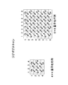
- FIG. 19 shows a scan pattern of an existing zigzag scan.
- FIG. 20 conceptually shows a state of encoding by the zigzag scan and the DPCM method.
- HEVC High Efficiency Video Coding
- CU Coding Unit
- SCU Smallest Coding Unit
- one coding unit may be divided into one or more orthogonal transform units, that is, one or more transform units (TU).
- TU transform units
- any of 4 ⁇ 4, 8 ⁇ 8, 16 ⁇ 16, and 32 ⁇ 32 can be used.
- a quantization matrix can also be specified for each available transform unit size.
- Non-Patent Document 2 below defines a plurality of quantization matrix candidates for the size of one transform unit in one picture, and adaptively applies a quantization matrix for each block from the viewpoint of optimization of RD (Rate-Distortion). Suggest to choose.
- JCTVC-B205 "Test Model under Consideration”, Joint Collaborative Team on Video Coding (JCT-VC) of ITU-T SG16 WP3 and ISO / IEC JTC1 / SC29 / WG11 2nd Meeting: Geneva, CH, 21-28 July, 2010
- VCEG-AD06 "Adaptive Quantization Matrix Selection on KTA Software”
- the quantization matrix suitable for quantization and inverse quantization differs depending on the characteristics of each image included in the video. Therefore, H.H.
- the correlation between adjacent components in the one-dimensional array converted from the quantization matrix is not necessarily high, and as a result, the amount of code required for defining the quantization matrix is reduced. In some cases, it could not be compressed sufficiently.
- the number of quantization matrices defined accordingly increases. Therefore, it is expected that the need to further compress the code amount required for defining the quantization matrix will increase.
- the technology according to the present disclosure is intended to provide an image processing apparatus and an image processing method that can further compress the amount of code required for defining a quantization matrix.
- an acquisition unit that acquires a scan pattern parameter that specifies a scan pattern used when generating a quantization matrix among a plurality of scan patterns, and the scan pattern parameter acquired by the acquisition unit
- a generation unit that generates a quantization matrix using a scan pattern specified by the above, and an inverse quantization unit that dequantizes transform coefficient data of an image to be decoded using the quantization matrix generated by the generation unit
- the image processing apparatus can typically be realized as an image decoding apparatus that decodes an image.
- the acquisition unit acquires a presence parameter indicating whether the scan pattern parameter exists, and acquires the scan pattern parameter when the presence parameter indicates that the scan pattern parameter exists. Also good.
- the acquisition unit may acquire one existence parameter for a plurality of types of quantization matrices defined in the same parameter set.
- the generation unit generates a quantization matrix by decoding the predictive-coded one-dimensional array and reconstructing the decoded one-dimensional array into a matrix according to the scan pattern specified by the scan pattern parameter. May be.
- the generator when the scan pattern specified by the scan pattern parameter is a predetermined scan pattern, the generator generates at least one element of the one-dimensional array based on prediction from an element different from the immediately preceding element. May be decrypted.
- one of the plurality of scan patterns may be a scan pattern in which the uppermost row and the leftmost column of the quantization matrix are respectively scanned straight.
- acquiring a scan pattern parameter for specifying a scan pattern used when generating a quantization matrix among a plurality of scan patterns and specifying the acquired scan pattern parameter
- An image processing method includes generating a quantization matrix using the generated scan pattern and dequantizing the transform coefficient data of the decoded image using the generated quantization matrix.
- a quantization unit that quantizes transform coefficient data of an image to be encoded using a quantization matrix, and a quantization used by the quantization unit among a plurality of scan patterns
- An image processing apparatus includes an encoding unit that encodes a scan pattern parameter that specifies a scan pattern used when generating a matrix.
- the image processing apparatus can typically be realized as an image encoding apparatus that encodes an image.
- the image processing apparatus may further include a setting unit that sets a scan pattern that optimizes a code amount required for defining the quantization matrix among the plurality of scan patterns.
- the setting unit may select the scan pattern that optimizes the code amount offline.
- the image processing apparatus may further include a transmission unit that transmits an encoded stream including the scan pattern parameter encoded by the encoding unit to a device that decodes the image.
- encoding a scan pattern parameter that specifies a scan pattern used when generating a quantization matrix among a plurality of scan patterns, and transform coefficients of an image to be encoded
- An image processing method includes quantizing data using the quantization matrix.
- the image processing apparatus and the image processing method according to the present disclosure can further compress the code amount required for defining the quantization matrix.
- FIG. 2 is a block diagram illustrating an example of a detailed configuration of a syntax processing unit illustrated in FIG. 1. It is explanatory drawing which shows an example of the parameter for the definition of the quantization matrix which concerns on one Embodiment. It is explanatory drawing for demonstrating the 1st example of a new scan pattern. It is explanatory drawing for demonstrating the 2nd example of a new scan pattern. It is explanatory drawing for demonstrating the 3rd example of a new scan pattern. It is explanatory drawing for demonstrating the 4th example of a new scan pattern. It is explanatory drawing for demonstrating the 5th example of a new scan pattern.
- H. 2 is an explanatory diagram illustrating a scan pattern of a zigzag scan in H.264 / AVC. It is explanatory drawing which shows notionally the mode of the encoding by a zigzag scan and a DPCM system.
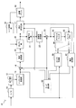
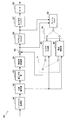
- FIG. 1 is a block diagram illustrating an example of a configuration of an image encoding device 10 according to an embodiment.
- an image encoding device 10 includes an A / D (Analogue to Digital) conversion unit 11, a rearrangement buffer 12, a syntax processing unit 13, a subtraction unit 14, an orthogonal transformation unit 15, a quantization unit 16, Lossless encoding unit 17, accumulation buffer 18, rate control unit 19, inverse quantization unit 21, inverse orthogonal transformation unit 22, addition unit 23, deblock filter 24, frame memory 25, selector 26, intra prediction unit 30, motion search Unit 40 and mode selection unit 50.
- a / D Analogue to Digital
- the A / D converter 11 converts an image signal input in an analog format into image data in a digital format, and outputs a series of digital image data to the rearrangement buffer 12.
- the rearrangement buffer 12 rearranges the images included in the series of image data input from the A / D conversion unit 11.
- the rearrangement buffer 12 rearranges the images according to a GOP (Group of Pictures) structure related to the encoding process, and then outputs the rearranged image data to the syntax processing unit 13.
- GOP Group of Pictures
- the syntax processing unit 13 sequentially recognizes NAL (Network Abstraction Layer) units in the stream of image data input from the rearrangement buffer 12, and inserts a non-VCL NAL unit that stores header information into the stream. To do.
- the non-VCL NAL unit inserted into the stream by the syntax processing unit 13 includes a sequence parameter set (SPS: Sequence Parameter Set) and a picture parameter set (PPS: Picture Parameter Set).
- SPS Sequence Parameter Set
- PPS Picture Parameter Set
- the syntax processing unit 13 adds a slice header to the head of the slice. Then, the syntax processing unit 13 outputs a stream of image data including the VCL NAL unit and the non-VCL NAL unit to the subtraction unit 14, the intra prediction unit 30, and the motion search unit 40.
- SPS Sequence Parameter Set
- PPS Picture Parameter Set
- the subtraction unit 14 is supplied with image data input from the syntax processing unit 13 and predicted image data selected by a mode selection unit 50 described later.
- the subtraction unit 14 calculates prediction error data that is a difference between the image data input from the syntax processing unit 13 and the predicted image data input from the mode selection unit 50, and the calculated prediction error data is orthogonally converted unit 15. Output to.
- the orthogonal transform unit 15 performs orthogonal transform on the prediction error data input from the subtraction unit 14.
- the orthogonal transformation performed by the orthogonal transformation part 15 may be discrete cosine transformation (Discrete Cosine Transform: DCT), Karoonen-Loeve transformation, etc., for example.
- the orthogonal transform unit 15 outputs transform coefficient data acquired by the orthogonal transform process to the quantization unit 16.
- the quantization unit 16 quantizes the transform coefficient data input from the orthogonal transform unit 15 using a quantization matrix, and transforms the quantized transform coefficient data (hereinafter referred to as quantized data) to the lossless encoding unit 17 and the inverse.
- the data is output to the quantization unit 21.
- the bit rate of the quantized data is controlled based on a rate control signal from the rate control unit 19.
- the quantization matrix used by the quantization unit 16 is defined in SPS or PPS, and can be specified in the slice header for each slice. If no quantization matrix is specified, a flat quantization matrix with equal quantization steps for all components is used.
- the lossless encoding unit 17 performs a lossless encoding process on the quantized data input from the quantization unit 16 to generate an encoded stream.
- the lossless encoding by the lossless encoding unit 17 may be, for example, variable length encoding or arithmetic encoding. Further, the lossless encoding unit 17 multiplexes information related to intra prediction or information related to inter prediction input from the mode selection unit 50 in the header of the encoded stream. Then, the lossless encoding unit 17 outputs the generated encoded stream to the accumulation buffer 18.
- the accumulation buffer 18 temporarily accumulates the encoded stream input from the lossless encoding unit 17 using a storage medium such as a semiconductor memory. Then, the accumulation buffer 18 outputs the accumulated encoded stream to a transmission unit (not shown) (for example, a communication interface or a connection interface with peripheral devices) at a rate corresponding to the bandwidth of the transmission path.
- a transmission unit for example, a communication interface or a connection interface with peripheral devices
- the rate control unit 19 monitors the free capacity of the storage buffer 18. Then, the rate control unit 19 generates a rate control signal according to the free capacity of the accumulation buffer 18 and outputs the generated rate control signal to the quantization unit 16. For example, the rate control unit 19 generates a rate control signal for reducing the bit rate of the quantized data when the free capacity of the storage buffer 18 is small. For example, when the free capacity of the storage buffer 18 is sufficiently large, the rate control unit 19 generates a rate control signal for increasing the bit rate of the quantized data.
- the inverse quantization unit 21 performs an inverse quantization process on the quantized data input from the quantization unit 16 using a quantization matrix. Then, the inverse quantization unit 21 outputs transform coefficient data acquired by the inverse quantization process to the inverse orthogonal transform unit 22.
- the inverse orthogonal transform unit 22 restores the prediction error data by performing an inverse orthogonal transform process on the transform coefficient data input from the inverse quantization unit 21. Then, the inverse orthogonal transform unit 22 outputs the restored prediction error data to the addition unit 23.
- the addition unit 23 generates decoded image data by adding the restored prediction error data input from the inverse orthogonal transform unit 22 and the predicted image data input from the mode selection unit 50. Then, the addition unit 23 outputs the generated decoded image data to the deblock filter 24 and the frame memory 25.
- the deblocking filter 24 performs a filtering process for reducing block distortion that occurs during image coding.
- the deblocking filter 24 removes block distortion by filtering the decoded image data input from the adding unit 23, and outputs the decoded image data after filtering to the frame memory 25.
- the frame memory 25 stores the decoded image data input from the adder 23 and the decoded image data after filtering input from the deblock filter 24 using a storage medium.
- the selector 26 reads out the decoded image data before filtering used for intra prediction from the frame memory 25 and supplies the read decoded image data to the intra prediction unit 30 as reference image data. Further, the selector 26 reads out the filtered decoded image data used for inter prediction from the frame memory 25 and supplies the read decoded image data to the motion search unit 40 as reference image data.
- the intra prediction unit 30 performs intra prediction processing in each intra prediction mode based on the image data to be encoded input from the syntax processing unit 13 and the decoded image data supplied via the selector 26. For example, the intra prediction unit 30 evaluates the prediction result in each intra prediction mode using a predetermined cost function. Then, the intra prediction unit 30 selects an intra prediction mode in which the cost function value is minimum, that is, an intra prediction mode in which the compression rate is the highest as the optimal intra prediction mode. Further, the intra prediction unit 30 outputs information related to intra prediction, such as prediction mode information indicating the optimal intra prediction mode, predicted image data, and cost function value, to the mode selection unit 50.
- the motion search unit 40 performs inter prediction processing (interframe prediction processing) based on the image data to be encoded input from the syntax processing unit 13 and the decoded image data supplied via the selector 26. For example, the motion search unit 40 evaluates the prediction result in each prediction mode using a predetermined cost function. Next, the motion search unit 40 selects a prediction mode with the smallest cost function value, that is, a prediction mode with the highest compression rate, as the optimum prediction mode. Further, the motion search unit 40 generates predicted image data according to the optimal prediction mode. Then, the motion search unit 40 outputs information related to inter prediction such as prediction mode information, prediction image data, and cost function values to the mode selection unit 50.
- inter prediction processing interframe prediction processing
- the mode selection unit 50 compares the cost function value related to intra prediction input from the intra prediction unit 30 with the cost function value related to inter prediction input from the motion search unit 40. And the mode selection part 50 selects the prediction method with few cost function values among intra prediction and inter prediction.
- the mode selection unit 50 outputs information on the intra prediction to the lossless encoding unit 17 and outputs the predicted image data to the subtraction unit 14 and the addition unit 23.
- the mode selection unit 50 outputs the above-described information regarding inter prediction to the lossless encoding unit 17 and outputs the predicted image data to the subtraction unit 14 and the addition unit 23.
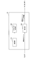
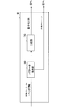
- FIG. 2 is a block diagram illustrating an example of a detailed configuration of the syntax processing unit 13 of the image encoding device 10 illustrated in FIG. 1.
- the syntax processing unit 13 includes a setting unit 110, a parameter generation unit 120, and an insertion unit 130.
- the setting unit 110 holds various settings used for encoding processing by the image encoding device 10.
- the setting unit 110 holds data relating to a profile of each sequence of image data, a coding mode of each picture, a GOP structure, and the like.
- the setting unit 110 holds settings for the quantization matrix used by the quantization unit 16 (and the inverse quantization unit 21).
- the setting unit 110 determines in advance for each slice, which quantization matrix to use by the quantization unit 16 based on the analysis of the image.
- the quantization matrix suitable for quantization and inverse quantization differs depending on the characteristics of each image included in the video.
- a quantization matrix having a smaller quantization step can be used even in a high frequency range.
- the quantization matrix changes in picture units or frame units.
- the complexity of the input image is low, the image quality perceived by the user can be improved by using a flat quantization matrix having a smaller quantization step.
- the complexity of the input image is high, it is desirable to use a larger quantization step in order to suppress an increase in the code amount.
- the distortion of the low-frequency signal may be recognized as block noise. Therefore, it is beneficial to reduce noise by using a quantization matrix in which the quantization step increases from the low range to the high range.
- MPEG2 compression distortion such as mosquito noise in the input image itself.
- Mosquito noise is noise generated as a result of quantizing a high-frequency signal with a larger quantization step, and the frequency component of the noise itself has a very high frequency.
- the interlace signal has a higher correlation between the signals in the horizontal direction than the correlation between the signals in the vertical direction due to the influence of interlaced scanning. Therefore, it is also beneficial to use a different quantization matrix depending on whether the image signal is a progressive signal or an interlace signal.
- each quantization matrix into a one-dimensional array for encoding
- a plurality of scan patterns including scan patterns other than the zigzag scan are prepared in advance.
- the setting unit 110 evaluates the code amount generated when the quantization matrix is encoded for each scan pattern, and selects an optimal scan pattern that minimizes the code amount.
- the determination of the quantization matrix and selection of the optimum scan pattern by the setting unit 110 are typically performed offline prior to image encoding. By selecting the optimum scan pattern offline, even when there are many scan pattern candidates, it is possible to appropriately find the optimum scan pattern using, for example, the brute force method. Then, the setting unit 110 holds, as the setting for the quantization matrix, the identifier of the optimum scan pattern selected offline for each quantization matrix defined in the parameter set.
- the parameter generation unit 120 generates a parameter that defines the setting for the encoding process held by the setting unit 110, and outputs the generated parameter to the insertion unit 130.
- the parameter generation unit 120 generates a parameter for defining a quantization matrix used by the quantization unit 16.
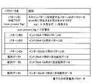
- FIG. 3 shows an example of parameters for defining the quantization matrix generated by the parameter generation unit 120.
- the “pattern ID presence flag” is a flag indicating whether or not a pattern ID that is a parameter for specifying a scan pattern exists in the parameter set (also referred to as a presence parameter).
- the pattern ID presence flag indicates “0: does not exist”, there is no pattern ID in the parameter set.
- the user-specific quantization matrix may be defined using zigzag scanning according to existing techniques.
- the pattern ID presence flag indicates “1: exists”, the pattern ID exists in the parameter set.
- Pattern ID is an ID (identifier) that identifies an optimal scan pattern for defining a quantization matrix (also referred to as a scan pattern parameter).
- a plurality of pattern IDs respectively associated with individual types of quantization matrices can be included.
- the type of quantization matrix is typically identified by a combination of size, prediction scheme (intra prediction / inter prediction) and signal component (Y / Cb / Cr component).
- the pattern ID1 is associated with the Y component of size 4 ⁇ 4 intra prediction
- the pattern ID2 is associated with the Cb component of size 4 ⁇ 4 intra prediction
- the pattern IDn is associated with the Y component of size 32 ⁇ 32 inter prediction. It has been.
- Array data is data of a one-dimensional array that is predictively encoded by the DPCM method and defines the values of the elements of the quantization matrix.
- array data 1 is a Y component for intra prediction of size 4 ⁇ 4
- array data 2 is a Cb component of intra prediction of size 4 ⁇ 4
- array data n is a Y component of inter prediction of size 32 ⁇ 32. The data associated with each.
- the insertion unit 130 inserts header information such as SPS, PPS, and a slice header, each including a parameter group generated by the parameter generation unit 120, into a stream of image data input from the rearrangement buffer 12. .
- the SPS and the PPS may include parameters for defining the quantization matrix as illustrated in FIG.
- the slice header may include a parameter that specifies a quantization matrix to be used for quantization and inverse quantization for the slice among quantization matrices defined by SPS or PPS. Then, the insertion unit 130 outputs the stream of image data in which the header information is inserted to the subtraction unit 14, the intra prediction unit 30, and the motion search unit 40.
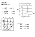
- Scan pattern candidates that can be set by the setting unit 110 of the syntax processing unit 13 include new scan patterns exemplified in FIGS. 4 to 8 in addition to the zigzag scan (see FIG. 19) that is an existing scan pattern. It's okay.
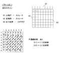
- FIG. 4 is an explanatory diagram for describing a first example of a new scan pattern.
- the scan pattern shown in FIG. 4 is referred to as “mixed scan” in this specification.
- the mixed scan the uppermost row and the leftmost column of the quantization matrix are scanned straight (S1, S2), and the remaining square elements are scanned zigzag (S3). Is a combined scan pattern.
- the element in the i-th row and j-th column of the quantization matrix is represented as (i, j).
- the mixed scan first, the eight elements (1, 1) to (1, 8) in the top row are scanned straight in the horizontal direction. Next, the seven elements (2, 1) to (8, 1) in the left end row are scanned straight in the vertical direction. Thereafter, the remaining lower right square elements (2, 2) to (8, 8) are scanned zigzag.
- the scan pattern is not a so-called one-stroke drawing like the existing zigzag scan, but has a branch in the middle of the scan pattern.
- the meaning of this branch is that the value of the element located in each branch is determined from the value of the element (two or more previous elements in the one-dimensional array) different from the previous element when encoding in the DPCM method. That is to be predicted.
- the element immediately before the first element (2, 1) of the straight scan in the leftmost column is the last element (1, 8) of the straight scan in the uppermost row.
- the element (1, 1) is used as a reference element instead of the element (1, 8).
- the difference between the value of the element (2, 1) and the value of the reference element (1, 1) is encoded.
- the element immediately before the first element (2, 2) of the lower right square zigzag scan is the last element (8, 1) of the straight scan of the left end column.
- the element (2, 1) is used as the reference element instead of the element (8, 1).
- the difference between the value of the element (2, 2) and the value of the reference element (2, 1) is encoded.
- an element encoded with reference to an element different from the immediately preceding element is referred to as a discontinuous reference element.
- the elements (2, 1) and (2, 2) are discontinuous reference elements.
- discontinuous reference element typically uses an element located closer to the two-dimensional quantization matrix as a reference element (element serving as a basis for prediction) instead of the immediately preceding element. This is because in a normally used quantization matrix, there is a high correlation of values between elements located near each other.
- FIG. 5 is an explanatory diagram for describing a second example of a new scan pattern.
- the scan pattern shown in FIG. 5 is referred to as “divided mixed scan” in this specification.
- the divided mixed scan first, the eight elements (1, 1) to (1, 8) in the upper end row are scanned straight in the horizontal direction (S1).
- the seven elements (2, 1) to (8, 1) in the left end row are scanned straight in the vertical direction (S2).
- the upper right triangular element groups (2, 2) to (8, 8) divided by diagonal lines in the remaining quadrangular regions are scanned zigzag (S3).
- the remaining lower left triangular element groups (3, 2) to (8, 7) are scanned zigzag (S4).
- the divided mixed scan also has a branch in the middle of the scan pattern.
- the elements (2, 1), (2, 2), and (3, 2) are discontinuous reference elements.
- the difference from the value of the reference element (1, 1) is encoded instead of the immediately preceding element (1, 8).
- the difference from the value of the reference element (2, 1) is encoded instead of the immediately preceding element (8, 1).
- the difference from the value of the reference element (2, 2) is encoded instead of the immediately preceding element (8, 8).
- Both the first example and the second example of the new scan pattern are scan patterns combining a straight scan and a zigzag scan.
- the straight scan is performed particularly on the uppermost row and the leftmost column of the quantization matrix.
- Such a scan pattern is useful when orthogonal transform coefficients are concentrated on the elements in the uppermost row and the leftmost column of the transform unit, and the correlation of the quantization step between these elements is high (in fact, Such quantization matrices can be used frequently).
- the second example is useful when the correlation between the upper right half element group and the lower left half element group is low, and it is better to scan these separately.
- FIG. 6 is an explanatory diagram for describing a third example of a new scan pattern.
- the scan pattern shown in FIG. 6 is a so-called field scan.
- the field scan has no branch in the middle of the scan pattern. Therefore, there is no discontinuous reference element in the field scan.
- the third example is useful when the correlation between quantization steps along the scan direction of the field scan is high.
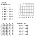
- FIG. 7 is an explanatory diagram for describing a fourth example of a new scan pattern.
- the scan pattern shown in FIG. 7 is referred to as “vertical stripe scan” in this specification.
- vertical stripe scan first, the eight elements (1, 1) to (8, 1) in the left end row are scanned straight in the vertical direction (S1). Next, the eight elements (1, 2) to (8, 2) in the second column from the left are scanned straight in the vertical direction (S2). Thereafter, vertical scanning in the vertical direction is repeated in order from the third column to the eighth column (S3 to S8).
- the elements (1, 2), (1, 3), (1, 4), (1, 5), (1, 6), (1, 7) and (1, 8) are discontinuous.
- Reference element When the element (1, 2) is encoded, the difference from the value of the reference element (1, 1) is encoded instead of the immediately preceding element (8, 1). When encoding the element (1, 3), the difference from the value of the reference element (1, 2) is encoded instead of the immediately preceding element (8, 2). Also for other discontinuous reference elements, not the immediately preceding element in the one-dimensional array after scanning, but the difference from the values of two or more previous elements is encoded.
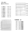
- FIG. 8 is an explanatory diagram for describing a fifth example of a new scan pattern.
- the scan pattern shown in FIG. 8 is referred to as “horizontal stripe scan” in this specification.
- the horizontal stripe scan first, the eight elements (1, 1) to (1, 8) in the upper end row are scanned straight in the horizontal direction (S1).
- the eight elements (2, 1) to (2, 8) in the second row from the top are scanned straight in the horizontal direction (S2).
- the horizontal straight scan is sequentially repeated from the third row to the eighth row (S3 to S8).
- the horizontal stripe scan has a branch in the middle of the scan pattern.
- elements (2,1), (3,1), (4,1), (5,1), (6,1), (7,1) and (8,1) are discontinuous Reference element.
- the difference from the value of the reference element (1, 1) is encoded instead of the immediately preceding element (1, 8).
- the difference from the value of the reference element (2, 1) is encoded instead of the immediately preceding element (2, 8).
- the immediately preceding element in the one-dimensional array after scanning but the difference from the values of two or more previous elements is encoded.
- the fourth example and the fifth example of the new scan pattern are both scan patterns composed of only a straight scan. Such a scan pattern is when the correlation of quantization steps between elements along one of the vertical and horizontal directions is high and the correlation of quantization steps between elements along the other is low. Useful.
- FIG. 9 is a flowchart showing an example of the flow of parameter generation processing by the parameter generation unit 120 of the syntax processing unit 13 according to the present embodiment.
- the parameter generation process shown in FIG. 9 is a process that can be executed for a quantization matrix to be defined when there is a quantization matrix to be newly defined.
- the parameter generation unit 120 recognizes the optimum scan pattern selected offline by the setting unit 110 corresponding to the quantization matrix to be newly defined (step S100).
- the subsequent steps S104 to S110 are repeated for each element of the quantization matrix (step S102).
- the order of the elements to be processed follows the scan pattern recognized in step S100.
- the parameter generation unit 120 acquires the value of an element to be processed (hereinafter referred to as a target element) in the quantization matrix according to the scan pattern (step S104).
- the parameter generation unit 120 determines whether or not the element of interest is a discontinuous reference element (step S106). If the target element is not a discontinuous reference element, the parameter generation unit 120 determines the difference value between the immediately preceding element (the previous target element) and the target element (for the first target element, the target element Is stored in a one-dimensional array (step S108). On the other hand, if the element of interest is a discontinuous reference element, the parameter generation unit 120 stores the difference value between the predetermined reference element before the immediately preceding element and the element of interest in a one-dimensional array (step) S110).
- a set of pattern IDk and array data k (k is any one of 1 to n) is generated.
- the parameter generation unit 120 performs the above-described parameter generation processing on a quantization matrix (one or more types) to be newly defined, for example, at the timing when SPS or PPS is inserted into a stream of image data.
- the parameters generated by the parameter generation unit 120 are included in the SPS or PPS by the insertion unit 130.
- the pattern ID presence flag indicates “1: exists”.
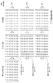
- FIG. 10B there is shown a quantization matrix QM B as another example that may be defined by the user.
- QM B the sequence shown in the upper center of FIG. (6,6,10,13, ..., 27) is derived.
- the one-dimensional array generated by the zigzag scan is encoded according to the DPCM method, the one-dimensional array (6, 0, 4, 3,..., 0) of the difference values shown on the upper right of the figure is derived.
- the total sum of absolute values of the elements of the one-dimensional array of difference values generated in this way is 167.
- the setting unit 110 may evaluate the code amount for each scan pattern in this way for each quantization matrix, and may select the optimum scan pattern with the smallest code amount. Thereby, compared with the case where a quantization matrix is uniformly arranged in a one-dimensional array by zigzag scanning, the amount of code required for defining the quantization matrix can be further compressed.
- the elements surrounded by the dotted frame are discontinuous reference elements.
- FIG. 11 is a block diagram illustrating an example of the configuration of the image decoding device 60 according to an embodiment.
- the image decoding device 60 includes a syntax processing unit 61, a lossless decoding unit 62, an inverse quantization unit 63, an inverse orthogonal transform unit 64, an addition unit 65, a deblocking filter 66, a rearrangement buffer 67, a D / A (Digital to Analogue) conversion unit 68, frame memory 69, selectors 70 and 71, intra prediction unit 80, and motion compensation unit 90.
- a syntax processing unit 61 includes a syntax processing unit 61, a lossless decoding unit 62, an inverse quantization unit 63, an inverse orthogonal transform unit 64, an addition unit 65, a deblocking filter 66, a rearrangement buffer 67, a D / A (Digital to Analogue) conversion unit 68, frame memory 69, selectors 70 and 71, intra prediction unit 80, and motion compensation unit 90.
- the syntax processing unit 61 acquires header information such as SPS, PPS, and slice header from the encoded stream input via the transmission path, and performs decoding processing by the image decoding device 60 based on the acquired header information. Recognize various settings. For example, in the present embodiment, the syntax processing unit 61 generates a quantization matrix used in the inverse quantization process by the inverse quantization unit 63 based on the parameters included in the SPS or PPS. The detailed configuration of the syntax processing unit 61 will be further described later.
- the lossless decoding unit 62 decodes the encoded stream input from the syntax processing unit 61 according to the encoding method used for encoding. Then, the lossless decoding unit 62 outputs the decoded quantized data to the inverse quantization unit 63. Further, the lossless decoding unit 62 outputs information related to intra prediction included in the header information to the intra prediction unit 80, and outputs information related to inter prediction to the motion compensation unit 90.
- the inverse quantization unit 63 uses the quantization matrix generated by the syntax processing unit 61 to inversely quantize the quantized data (that is, quantized transform coefficient data) after being decoded by the lossless decoding unit 62. .
- the quantization matrices generated by the syntax processing unit 61 which quantization matrix should be used for each block in a certain slice can be specified in the slice header.
- the inverse orthogonal transform unit 64 generates prediction error data by performing inverse orthogonal transform on the transform coefficient data input from the inverse quantization unit 63 in accordance with the orthogonal transform method used at the time of encoding. Then, the inverse orthogonal transform unit 64 outputs the generated prediction error data to the addition unit 65.
- the addition unit 65 adds the prediction error data input from the inverse orthogonal transform unit 64 and the prediction image data input from the selector 71 to generate decoded image data. Then, the addition unit 65 outputs the generated decoded image data to the deblock filter 66 and the frame memory 69.
- the deblocking filter 66 removes block distortion by filtering the decoded image data input from the adding unit 65, and outputs the decoded image data after filtering to the rearrangement buffer 67 and the frame memory 69.
- the rearrangement buffer 67 rearranges the images input from the deblock filter 66 to generate a series of time-series image data. Then, the rearrangement buffer 67 outputs the generated image data to the D / A conversion unit 68.
- the D / A converter 68 converts the digital image data input from the rearrangement buffer 67 into an analog image signal. Then, the D / A conversion unit 68 displays an image by outputting an analog image signal to a display (not shown) connected to the image decoding device 60, for example.
- the frame memory 69 stores the decoded image data before filtering input from the adding unit 65 and the decoded image data after filtering input from the deblocking filter 66 using a storage medium.
- the selector 70 switches the output destination of the image data from the frame memory 69 between the intra prediction unit 80 and the motion compensation unit 90 for each block in the image according to the mode information acquired by the lossless decoding unit 62. .
- the selector 70 outputs the decoded image data before filtering supplied from the frame memory 69 to the intra prediction unit 80 as reference image data.
- the selector 70 outputs the decoded image data after filtering supplied from the frame memory 69 to the motion compensation unit 90 as reference image data.
- the selector 71 sets the output source of the predicted image data to be supplied to the adding unit 65 for each block in the image according to the mode information acquired by the lossless decoding unit 62 between the intra prediction unit 80 and the motion compensation unit 90. Switch between. For example, the selector 71 supplies the prediction image data output from the intra prediction unit 80 to the adding unit 65 when the intra prediction mode is designated. The selector 71 supplies the predicted image data output from the motion compensation unit 90 to the adding unit 65 when the inter prediction mode is designated.
- the intra prediction unit 80 performs in-screen prediction of pixel values based on information related to intra prediction input from the lossless decoding unit 62 and reference image data from the frame memory 69, and generates predicted image data. Then, the intra prediction unit 80 outputs the generated predicted image data to the selector 71.
- the motion compensation unit 90 performs motion compensation processing based on the inter prediction information input from the lossless decoding unit 62 and the reference image data from the frame memory 69, and generates predicted image data. Then, the motion compensation unit 90 outputs the generated predicted image data to the selector 71.
- FIG. 12 is a block diagram illustrating an example of a detailed configuration of the syntax processing unit 61 of the image decoding device 60 illustrated in FIG. 11.
- the syntax processing unit 61 includes a parameter acquisition unit 160 and a generation unit 170.
- the parameter acquisition unit 160 recognizes header information such as SPS, PPS, and slice header from the image data stream, and acquires parameters included in the header information. For example, in this embodiment, the parameter acquisition unit 160 acquires a parameter that defines a quantization matrix from SPS or PPS.
- the parameters that define the quantization matrix may include a pattern ID presence flag as exemplified in FIG. 3, and a pattern ID and array data for each type of quantization matrix. Then, the parameter acquisition unit 160 outputs the acquired parameters to the generation unit 170. Also, the parameter acquisition unit 160 outputs a stream of image data to the lossless decoding unit 62.
- the generation unit 170 generates various data used in the processing by each unit illustrated in FIG. 11 based on the parameters acquired by the parameter acquisition unit 160. For example, the generation unit 170 recognizes the range of the size of the encoding unit from the set of LCU and SCU values, and sets the size of the encoding unit according to the value of split_flag. Image data is decoded using the encoding unit set here as a unit of processing. In addition, the generation unit 170 further sets the size of the conversion unit. The inverse quantization performed by the inverse quantization unit 63 and the inverse orthogonal transform performed by the inverse orthogonal transform unit 64 are performed using the transform unit set here as a processing unit.
- the generation unit 170 generates a quantization matrix based on the parameters acquired from the SPS or PPS by the parameter acquisition unit 160. More specifically, the generation unit 170 decodes array data that is a predictive-coded one-dimensional array according to the DPCM method, and reconstructs the decoded one-dimensional array into a two-dimensional quantization matrix. When a pattern ID that specifies one of a plurality of scan patterns is acquired from the parameter set, the reconstruction of the quantization matrix from the one-dimensional array is performed using the scan pattern specified by the pattern ID. Is called.
- the generation unit 170 determines at least one discontinuous reference element of the one-dimensional array based on a prediction from a reference element different from the immediately preceding element.
- the predetermined scan pattern can include, for example, the above-described mixed scan, divided mixed scan, vertical stripe scan, and horizontal stripe scan.
- the reconstruction of the quantization matrix is performed with a scan pattern of zigzag scan.
- the generation unit 170 can determine whether a pattern ID exists in the parameter set from the value indicated by the pattern ID presence flag. Only one pattern ID presence flag may be provided in common for a plurality of types of quantization matrices defined in the same parameter set. As a result, when a quantization matrix is to be defined according to an existing method, it can be simply indicated by a small code amount that there is no pattern ID.
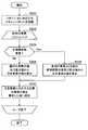
- FIG. 13 is a flowchart showing an exemplary flow of a quantization matrix generation process by the syntax processing unit 61 according to this embodiment.
- the quantization matrix generation process of FIG. 13 is a process that can be performed every time SPS or PPS is detected in a stream of image data.
- the parameter acquisition unit 160 first acquires a pattern ID presence flag from the SPS or PPS (step S200). The subsequent processing in steps S204 to S212 is repeated for each type of quantization matrix (step S202).
- step S204 the parameter acquisition unit 160 determines whether a pattern ID exists in the parameter set from the value indicated by the pattern ID presence flag (step S204). If it is determined that there is a pattern ID, the parameter acquisition unit 160 further acquires a pattern ID and array data for the type of quantization matrix to be processed (step S206). Then, the generation unit 170 performs a quantization matrix reconstruction process illustrated in FIG. 14 (Step S208). On the other hand, when it is determined that the pattern ID does not exist, the parameter acquisition unit 160 further acquires only the array data regarding the type of the quantization matrix to be processed (step S210). Then, the generation unit 170 performs a quantization matrix reconstruction process using a zigzag scan as in the existing method (step S212).
- FIG. 14 is a flowchart showing an example of a detailed flow of the quantization matrix reconstruction process in step S208 of FIG.
- the generation unit 170 recognizes a scan pattern corresponding to the pattern ID acquired by the parameter acquisition unit 160 (step S220).
- the subsequent processing in steps S224 to S230 is repeated for each element of the one-dimensional array included in the array data (step S222).
- step S224 the generation unit 170 determines whether or not the element of interest is a discontinuous reference element (step S224). If the target element is not a discontinuous reference element, the generation unit 170 adds the difference value of the target element included in the array data to the decoded value of the immediately preceding element (the previous target element), The decoded value of the element of interest is calculated (step S226). On the other hand, when the target element is a discontinuous reference element, the generation unit 170 adds the difference value of the target element to the decoded value of the predetermined reference element before the previous element, thereby generating the target element. Is calculated (step S228). Next, the generation unit 170 sets the value of the element corresponding to the element of interest in the quantization matrix to the value calculated in step S226 or S228 (step S230).
- the image encoding device 10 and the image decoding device 60 include a transmitter or a receiver in satellite broadcasting, cable broadcasting such as cable TV, distribution on the Internet, and distribution to terminals by cellular communication,
- the present invention can be applied to various electronic devices such as a recording apparatus that records an image on a medium such as an optical disk, a magnetic disk, and a flash memory, or a reproducing apparatus that reproduces an image from the storage medium.
- a recording apparatus that records an image on a medium such as an optical disk, a magnetic disk, and a flash memory
- a reproducing apparatus that reproduces an image from the storage medium.
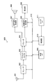
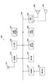
- FIG. 15 shows an example of a schematic configuration of a television apparatus to which the above-described embodiment is applied.
- the television apparatus 900 includes an antenna 901, a tuner 902, a demultiplexer 903, a decoder 904, a video signal processing unit 905, a display unit 906, an audio signal processing unit 907, a speaker 908, an external interface 909, a control unit 910, a user interface 911, And a bus 912.
- Tuner 902 extracts a signal of a desired channel from a broadcast signal received via antenna 901, and demodulates the extracted signal. Then, the tuner 902 outputs the encoded bit stream obtained by the demodulation to the demultiplexer 903. In other words, the tuner 902 serves as a transmission unit in the television apparatus 900 that receives an encoded stream in which an image is encoded.
- the demultiplexer 903 separates the video stream and audio stream of the viewing target program from the encoded bit stream, and outputs each separated stream to the decoder 904. In addition, the demultiplexer 903 extracts auxiliary data such as EPG (Electronic Program Guide) from the encoded bit stream, and supplies the extracted data to the control unit 910. Note that the demultiplexer 903 may perform descrambling when the encoded bit stream is scrambled.
- EPG Electronic Program Guide
- the decoder 904 decodes the video stream and audio stream input from the demultiplexer 903. Then, the decoder 904 outputs the video data generated by the decoding process to the video signal processing unit 905. In addition, the decoder 904 outputs audio data generated by the decoding process to the audio signal processing unit 907.
- the video signal processing unit 905 reproduces the video data input from the decoder 904 and causes the display unit 906 to display the video.
- the video signal processing unit 905 may cause the display unit 906 to display an application screen supplied via a network.
- the video signal processing unit 905 may perform additional processing such as noise removal on the video data according to the setting.
- the video signal processing unit 905 may generate a GUI (Graphical User Interface) image such as a menu, a button, or a cursor, and superimpose the generated image on the output image.
- GUI Graphic User Interface
- the display unit 906 is driven by a drive signal supplied from the video signal processing unit 905, and displays a video or an image on a video screen of a display device (for example, a liquid crystal display, a plasma display, or an OLED).
- a display device for example, a liquid crystal display, a plasma display, or an OLED.
- the audio signal processing unit 907 performs reproduction processing such as D / A conversion and amplification on the audio data input from the decoder 904, and outputs audio from the speaker 908.
- the audio signal processing unit 907 may perform additional processing such as noise removal on the audio data.
- the external interface 909 is an interface for connecting the television apparatus 900 to an external device or a network.
- a video stream or an audio stream received via the external interface 909 may be decoded by the decoder 904. That is, the external interface 909 also has a role as a transmission unit in the television apparatus 900 that receives an encoded stream in which an image is encoded.
- the control unit 910 has a processor such as a CPU (Central Processing Unit) and a memory such as a RAM (Random Access Memory) and a ROM (Read Only Memory).
- the memory stores a program executed by the CPU, program data, EPG data, data acquired via a network, and the like.
- the program stored in the memory is read and executed by the CPU when the television device 900 is activated, for example.
- the CPU controls the operation of the television device 900 according to an operation signal input from the user interface 911, for example, by executing the program.
- the user interface 911 is connected to the control unit 910.
- the user interface 911 includes, for example, buttons and switches for the user to operate the television device 900, a remote control signal receiving unit, and the like.
- the user interface 911 detects an operation by the user via these components, generates an operation signal, and outputs the generated operation signal to the control unit 910.
- the bus 912 connects the tuner 902, the demultiplexer 903, the decoder 904, the video signal processing unit 905, the audio signal processing unit 907, the external interface 909, and the control unit 910 to each other.
- the decoder 904 has the function of the image decoding apparatus 60 according to the above-described embodiment. Therefore, it is possible to compress the code amount required for defining the quantization matrix for the video decoded by the television apparatus 900.
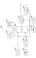
- FIG. 16 shows an example of a schematic configuration of a mobile phone to which the above-described embodiment is applied.
- a mobile phone 920 includes an antenna 921, a communication unit 922, an audio codec 923, a speaker 924, a microphone 925, a camera unit 926, an image processing unit 927, a demultiplexing unit 928, a recording / reproducing unit 929, a display unit 930, a control unit 931, an operation A portion 932 and a bus 933.
- the antenna 921 is connected to the communication unit 922.
- the speaker 924 and the microphone 925 are connected to the audio codec 923.
- the operation unit 932 is connected to the control unit 931.
- the bus 933 connects the communication unit 922, the audio codec 923, the camera unit 926, the image processing unit 927, the demultiplexing unit 928, the recording / reproducing unit 929, the display unit 930, and the control unit 931 to each other.
- the mobile phone 920 has various operation modes including a voice call mode, a data communication mode, a shooting mode, and a videophone mode, and is used for sending and receiving voice signals, sending and receiving e-mail or image data, taking images, and recording data. Perform the action.
- the analog voice signal generated by the microphone 925 is supplied to the voice codec 923.
- the audio codec 923 converts an analog audio signal into audio data, A / D converts the compressed audio data, and compresses it. Then, the audio codec 923 outputs the compressed audio data to the communication unit 922.
- the communication unit 922 encodes and modulates the audio data and generates a transmission signal. Then, the communication unit 922 transmits the generated transmission signal to a base station (not shown) via the antenna 921. In addition, the communication unit 922 amplifies a radio signal received via the antenna 921 and performs frequency conversion to acquire a received signal.
- the communication unit 922 demodulates and decodes the received signal to generate audio data, and outputs the generated audio data to the audio codec 923.
- the audio codec 923 expands the audio data and performs D / A conversion to generate an analog audio signal. Then, the audio codec 923 supplies the generated audio signal to the speaker 924 to output audio.
- the control unit 931 generates character data constituting the e-mail in response to an operation by the user via the operation unit 932.
- the control unit 931 causes the display unit 930 to display characters.
- the control unit 931 generates e-mail data in response to a transmission instruction from the user via the operation unit 932, and outputs the generated e-mail data to the communication unit 922.
- the communication unit 922 encodes and modulates email data and generates a transmission signal. Then, the communication unit 922 transmits the generated transmission signal to a base station (not shown) via the antenna 921.
- the communication unit 922 amplifies a radio signal received via the antenna 921 and performs frequency conversion to acquire a received signal.
- the communication unit 922 demodulates and decodes the received signal to restore the email data, and outputs the restored email data to the control unit 931.
- the control unit 931 displays the content of the electronic mail on the display unit 930 and stores the electronic mail data in the storage medium of the recording / reproducing unit 929.
- the recording / reproducing unit 929 has an arbitrary readable / writable storage medium.
- the storage medium may be a built-in storage medium such as a RAM or a flash memory, or an externally mounted storage medium such as a hard disk, a magnetic disk, a magneto-optical disk, an optical disk, a USB memory, or a memory card. May be.
- the camera unit 926 images a subject to generate image data, and outputs the generated image data to the image processing unit 927.
- the image processing unit 927 encodes the image data input from the camera unit 926 and stores the encoded stream in the storage medium of the recording / playback unit 929.
- the demultiplexing unit 928 multiplexes the video stream encoded by the image processing unit 927 and the audio stream input from the audio codec 923, and the multiplexed stream is the communication unit 922. Output to.
- the communication unit 922 encodes and modulates the stream and generates a transmission signal. Then, the communication unit 922 transmits the generated transmission signal to a base station (not shown) via the antenna 921.
- the communication unit 922 amplifies a radio signal received via the antenna 921 and performs frequency conversion to acquire a received signal.
- These transmission signal and reception signal may include an encoded bit stream.
- the communication unit 922 demodulates and decodes the received signal to restore the stream, and outputs the restored stream to the demultiplexing unit 928.
- the demultiplexing unit 928 separates the video stream and the audio stream from the input stream, and outputs the video stream to the image processing unit 927 and the audio stream to the audio codec 923.
- the image processing unit 927 decodes the video stream and generates video data.
- the video data is supplied to the display unit 930, and a series of images is displayed on the display unit 930.
- the audio codec 923 decompresses the audio stream and performs D / A conversion to generate an analog audio signal. Then, the audio codec 923 supplies the generated audio signal to the speaker 924 to output audio.
- the image processing unit 927 has the functions of the image encoding device 10 and the image decoding device 60 according to the above-described embodiment. Therefore, the amount of code required to define the quantization matrix can be compressed for video encoded and decoded by the mobile phone 920.
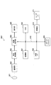
- FIG. 17 shows an example of a schematic configuration of a recording / reproducing apparatus to which the above-described embodiment is applied.
- the recording / reproducing device 940 encodes audio data and video data of a received broadcast program and records the encoded data on a recording medium.
- the recording / reproducing device 940 may encode audio data and video data acquired from another device and record them on a recording medium, for example.
- the recording / reproducing device 940 reproduces data recorded on the recording medium on a monitor and a speaker, for example, in accordance with a user instruction. At this time, the recording / reproducing device 940 decodes the audio data and the video data.
- the recording / reproducing device 940 includes a tuner 941, an external interface 942, an encoder 943, an HDD (Hard Disk Drive) 944, a disk drive 945, a selector 946, a decoder 947, an OSD (On-Screen Display) 948, a control unit 949, and a user interface. 950.
- Tuner 941 extracts a signal of a desired channel from a broadcast signal received via an antenna (not shown), and demodulates the extracted signal. Then, the tuner 941 outputs the encoded bit stream obtained by the demodulation to the selector 946. That is, the tuner 941 has a role as a transmission unit in the recording / reproducing apparatus 940.
- the external interface 942 is an interface for connecting the recording / reproducing apparatus 940 to an external device or a network.
- the external interface 942 may be, for example, an IEEE 1394 interface, a network interface, a USB interface, or a flash memory interface.
- video data and audio data received via the external interface 942 are input to the encoder 943. That is, the external interface 942 serves as a transmission unit in the recording / reproducing device 940.
- the encoder 943 encodes video data and audio data when the video data and audio data input from the external interface 942 are not encoded. Then, the encoder 943 outputs the encoded bit stream to the selector 946.
- the HDD 944 records an encoded bit stream in which content data such as video and audio is compressed, various programs, and other data on an internal hard disk. Also, the HDD 944 reads out these data from the hard disk when playing back video and audio.
- the disk drive 945 performs recording and reading of data to and from the mounted recording medium.
- the recording medium loaded in the disk drive 945 may be, for example, a DVD disk (DVD-Video, DVD-RAM, DVD-R, DVD-RW, DVD + R, DVD + RW, etc.) or a Blu-ray (registered trademark) disk. .
- the selector 946 selects an encoded bit stream input from the tuner 941 or the encoder 943 when recording video and audio, and outputs the selected encoded bit stream to the HDD 944 or the disk drive 945. In addition, the selector 946 outputs the encoded bit stream input from the HDD 944 or the disk drive 945 to the decoder 947 during video and audio reproduction.
- the decoder 947 decodes the encoded bit stream and generates video data and audio data. Then, the decoder 947 outputs the generated video data to the OSD 948. The decoder 904 outputs the generated audio data to an external speaker.
- the OSD 948 reproduces the video data input from the decoder 947 and displays the video. Further, the OSD 948 may superimpose a GUI image such as a menu, a button, or a cursor on the video to be displayed.
- a GUI image such as a menu, a button, or a cursor
- the control unit 949 includes a processor such as a CPU and memories such as a RAM and a ROM.
- the memory stores a program executed by the CPU, program data, and the like.
- the program stored in the memory is read and executed by the CPU when the recording / reproducing apparatus 940 is activated, for example.
- the CPU controls the operation of the recording / reproducing device 940 according to an operation signal input from the user interface 950, for example, by executing the program.
- the user interface 950 is connected to the control unit 949.
- the user interface 950 includes, for example, buttons and switches for the user to operate the recording / reproducing device 940, a remote control signal receiving unit, and the like.
- the user interface 950 detects an operation by the user via these components, generates an operation signal, and outputs the generated operation signal to the control unit 949.
- the encoder 943 has the function of the image encoding apparatus 10 according to the above-described embodiment.
- the decoder 947 has the function of the image decoding device 60 according to the above-described embodiment. Therefore, the code amount required for defining the quantization matrix can be compressed for the video encoded and decoded by the recording / reproducing apparatus 940.
- FIG. 18 illustrates an example of a schematic configuration of an imaging apparatus to which the above-described embodiment is applied.
- the imaging device 960 images a subject to generate an image, encodes the image data, and records it on a recording medium.
- the imaging device 960 includes an optical block 961, an imaging unit 962, a signal processing unit 963, an image processing unit 964, a display unit 965, an external interface 966, a memory 967, a media drive 968, an OSD 969, a control unit 970, a user interface 971, and a bus. 972.
- the optical block 961 is connected to the imaging unit 962.
- the imaging unit 962 is connected to the signal processing unit 963.
- the display unit 965 is connected to the image processing unit 964.
- the user interface 971 is connected to the control unit 970.
- the bus 972 connects the image processing unit 964, the external interface 966, the memory 967, the media drive 968, the OSD 969, and the control unit 970 to each other.
- the optical block 961 includes a focus lens and a diaphragm mechanism.
- the optical block 961 forms an optical image of the subject on the imaging surface of the imaging unit 962.
- the imaging unit 962 includes an image sensor such as a CCD or a CMOS, and converts an optical image formed on the imaging surface into an image signal as an electrical signal by photoelectric conversion. Then, the imaging unit 962 outputs the image signal to the signal processing unit 963.
- the signal processing unit 963 performs various camera signal processing such as knee correction, gamma correction, and color correction on the image signal input from the imaging unit 962.
- the signal processing unit 963 outputs the image data after the camera signal processing to the image processing unit 964.
- the image processing unit 964 encodes the image data input from the signal processing unit 963 and generates encoded data. Then, the image processing unit 964 outputs the generated encoded data to the external interface 966 or the media drive 968. The image processing unit 964 also decodes encoded data input from the external interface 966 or the media drive 968 to generate image data. Then, the image processing unit 964 outputs the generated image data to the display unit 965. In addition, the image processing unit 964 may display the image by outputting the image data input from the signal processing unit 963 to the display unit 965. Further, the image processing unit 964 may superimpose display data acquired from the OSD 969 on an image output to the display unit 965.
- the OSD 969 generates a GUI image such as a menu, a button, or a cursor, for example, and outputs the generated image to the image processing unit 964.
- the external interface 966 is configured as a USB input / output terminal, for example.
- the external interface 966 connects the imaging device 960 and a printer, for example, when printing an image.
- a drive is connected to the external interface 966 as necessary.
- a removable medium such as a magnetic disk or an optical disk is attached to the drive, and a program read from the removable medium can be installed in the imaging device 960.
- the external interface 966 may be configured as a network interface connected to a network such as a LAN or the Internet. That is, the external interface 966 has a role as a transmission unit in the imaging device 960.
- the recording medium mounted on the media drive 968 may be any readable / writable removable medium such as a magnetic disk, a magneto-optical disk, an optical disk, or a semiconductor memory. Further, a recording medium may be fixedly attached to the media drive 968, and a non-portable storage unit such as an internal hard disk drive or an SSD (Solid State Drive) may be configured.
- a non-portable storage unit such as an internal hard disk drive or an SSD (Solid State Drive) may be configured.
- the control unit 970 includes a processor such as a CPU and memories such as a RAM and a ROM.
- the memory stores a program executed by the CPU, program data, and the like.
- the program stored in the memory is read and executed by the CPU when the imaging device 960 is activated, for example.
- the CPU controls the operation of the imaging device 960 according to an operation signal input from the user interface 971, for example, by executing the program.
- the user interface 971 is connected to the control unit 970.
- the user interface 971 includes, for example, buttons and switches for the user to operate the imaging device 960.
- the user interface 971 detects an operation by the user via these components, generates an operation signal, and outputs the generated operation signal to the control unit 970.
- the image processing unit 964 has the functions of the image encoding device 10 and the image decoding device 60 according to the above-described embodiment. Therefore, it is possible to compress the amount of code required for defining the quantization matrix for the video encoded and decoded by the imaging device 960.
- the quantization matrix used in the quantization or inverse quantization of the transform coefficient data of the image is encoded using a scan pattern that is adaptively selected from a plurality of scan patterns. Or decrypted. Thereby, compared with the case where a zigzag scan is used uniformly, the code amount required for the definition of a quantization matrix can be compressed more.
- a flag indicating whether or not a pattern ID for specifying a scan pattern exists in the parameter set is inserted in the parameter set.
- One flag may be provided for a plurality of types of quantization matrices defined in the same parameter set. Therefore, when a quantization matrix is to be defined according to an existing method, it can be simply indicated that a pattern ID does not exist with a small code amount. As a result, the above-described adaptive scan pattern selection mechanism can be introduced without significantly affecting the existing apparatus.
- a discontinuous reference element can be adopted for a predetermined scan pattern.
- the encoding or decoding of the discontinuous reference element in the DPCM method is performed based on prediction from a reference element different from the element immediately before the one-dimensional array to be scanned.
- the parameters for defining the quantization matrix are multiplexed on the header of the encoded stream and transmitted from the encoding side to the decoding side.
- the method of transmitting these parameters is not limited to such an example.
- the parameters may be transmitted or recorded as separate data associated with the encoded bitstream without being multiplexed into the encoded bitstream.
- the term “associate” means that an image (which may be a part of an image such as a slice or a block) included in the bitstream and information corresponding to the image can be linked at the time of decoding. Means. That is, information may be transmitted on a transmission path different from that of the image (or bit stream).
- the information may be recorded on a recording medium (or another recording area of the same recording medium) different from the image (or bit stream). Furthermore, the information and the image (or the bit stream) may be associated with each other in an arbitrary unit such as a plurality of frames, one frame, or a part of the frame.
- Image processing device image encoding device
- quantization unit 110 setting unit 120 parameter generation unit 130 insertion unit
- parameter generation unit 120 parameter generation unit
- insertion unit 60 image processing device (image decoding device)
- Inverse quantization unit 160 Parameter acquisition unit 170 Generation unit
Landscapes
- Engineering & Computer Science (AREA)
- Multimedia (AREA)
- Signal Processing (AREA)
- Compression Or Coding Systems Of Tv Signals (AREA)
Abstract
La présente invention a pour objectif de compresser la quantité de code nécessaire pour définir une matrice de quantification. Pour atteindre cet objectif, la présente invention se rapporte à un appareil de traitement d'image comprenant : un module d'obtention, qui obtient un paramètre de motif de balayage pour spécifier un motif de balayage devant être utilisé lors de la génération d'une matrice de quantification, parmi une pluralité de motifs de balayage ; un module de génération, qui génère une matrice de quantification au moyen d'un motif de balayage spécifié par le paramètre de motif de balayage obtenu par le module d'obtention ; et un module de déquantification, qui déquantifie des données de coefficient de conversion d'une image devant être décodée, au moyen de la matrice de quantification générée par le module de génération.
Applications Claiming Priority (2)
| Application Number | Priority Date | Filing Date | Title |
|---|---|---|---|
| JP2011038159A JP2012175615A (ja) | 2011-02-24 | 2011-02-24 | 画像処理装置及び画像処理方法 |
| JP2011-038159 | 2011-02-24 |
Publications (1)
| Publication Number | Publication Date |
|---|---|
| WO2012114792A1 true WO2012114792A1 (fr) | 2012-08-30 |
Family
ID=46720581
Family Applications (1)
| Application Number | Title | Priority Date | Filing Date |
|---|---|---|---|
| PCT/JP2012/050928 Ceased WO2012114792A1 (fr) | 2011-02-24 | 2012-01-18 | Appareil de traitement d'image et procédé de traitement d'image |
Country Status (2)
| Country | Link |
|---|---|
| JP (1) | JP2012175615A (fr) |
| WO (1) | WO2012114792A1 (fr) |
Cited By (1)
| Publication number | Priority date | Publication date | Assignee | Title |
|---|---|---|---|---|
| US9948929B2 (en) | 2012-04-26 | 2018-04-17 | Sony Corporation | Quantization for different color sampling schemes |
Families Citing this family (1)
| Publication number | Priority date | Publication date | Assignee | Title |
|---|---|---|---|---|
| GB2519070A (en) | 2013-10-01 | 2015-04-15 | Sony Corp | Data encoding and decoding |
Citations (3)
| Publication number | Priority date | Publication date | Assignee | Title |
|---|---|---|---|---|
| JPH1093966A (ja) * | 1992-02-29 | 1998-04-10 | Samsung Electron Co Ltd | 画像符号化装置 |
| JP2008042701A (ja) * | 2006-08-09 | 2008-02-21 | Sony Corp | 画像データ処理方法および処理装置 |
| WO2008120434A1 (fr) * | 2007-03-28 | 2008-10-09 | Panasonic Corporation | Circuit de décodage, procédé de décodage, circuit de codage et procédé de codage |
-
2011
- 2011-02-24 JP JP2011038159A patent/JP2012175615A/ja not_active Withdrawn
-
2012
- 2012-01-18 WO PCT/JP2012/050928 patent/WO2012114792A1/fr not_active Ceased
Patent Citations (3)
| Publication number | Priority date | Publication date | Assignee | Title |
|---|---|---|---|---|
| JPH1093966A (ja) * | 1992-02-29 | 1998-04-10 | Samsung Electron Co Ltd | 画像符号化装置 |
| JP2008042701A (ja) * | 2006-08-09 | 2008-02-21 | Sony Corp | 画像データ処理方法および処理装置 |
| WO2008120434A1 (fr) * | 2007-03-28 | 2008-10-09 | Panasonic Corporation | Circuit de décodage, procédé de décodage, circuit de codage et procédé de codage |
Cited By (3)
| Publication number | Priority date | Publication date | Assignee | Title |
|---|---|---|---|---|
| US9948929B2 (en) | 2012-04-26 | 2018-04-17 | Sony Corporation | Quantization for different color sampling schemes |
| US10291909B2 (en) | 2012-04-26 | 2019-05-14 | Sony Corporation | Quantization for different color sampling schemes |
| US10616572B2 (en) | 2012-04-26 | 2020-04-07 | Sony Corporation | Quantization for different color sampling schemes |
Also Published As
| Publication number | Publication date |
|---|---|
| JP2012175615A (ja) | 2012-09-10 |
Similar Documents
| Publication | Publication Date | Title |
|---|---|---|
| US10931955B2 (en) | Image processing device and image processing method that horizontal filtering on pixel blocks | |
| US10499057B2 (en) | Image processing device and image processing method | |
| US10448017B2 (en) | Image processing device and image processing method for image decoding based on non-square quantization matrix | |
| US9998766B2 (en) | Image processing device and image processing method | |
| US20230055659A1 (en) | Image processing device and method using adaptive offset filter in units of largest coding unit | |
| WO2012153578A1 (fr) | Dispositif de traitement d'image et procédé de traitement d'image | |
| WO2014148070A1 (fr) | Dispositif de traitement d'image et procédé de traitement d'image | |
| WO2013051452A1 (fr) | Dispositif et procédé de traitement d'image | |
| US10412417B2 (en) | Image processing device and method capable of performing an encoding process or a decoding process on an image at high speed | |
| WO2012114792A1 (fr) | Appareil de traitement d'image et procédé de traitement d'image |
Legal Events
| Date | Code | Title | Description |
|---|---|---|---|
| 121 | Ep: the epo has been informed by wipo that ep was designated in this application |
Ref document number: 12749911 Country of ref document: EP Kind code of ref document: A1 |
|
| NENP | Non-entry into the national phase |
Ref country code: DE |
|
| 122 | Ep: pct application non-entry in european phase |
Ref document number: 12749911 Country of ref document: EP Kind code of ref document: A1 |