WO2012114812A1 - Dispositif de colonne de direction - Google Patents
Dispositif de colonne de direction Download PDFInfo
- Publication number
- WO2012114812A1 WO2012114812A1 PCT/JP2012/051475 JP2012051475W WO2012114812A1 WO 2012114812 A1 WO2012114812 A1 WO 2012114812A1 JP 2012051475 W JP2012051475 W JP 2012051475W WO 2012114812 A1 WO2012114812 A1 WO 2012114812A1
- Authority
- WO
- WIPO (PCT)
- Prior art keywords
- column
- displacement
- outer column
- side bracket
- portions
- Prior art date
- Legal status (The legal status is an assumption and is not a legal conclusion. Google has not performed a legal analysis and makes no representation as to the accuracy of the status listed.)
- Ceased
Links
Images


Classifications
-
- B—PERFORMING OPERATIONS; TRANSPORTING
- B62—LAND VEHICLES FOR TRAVELLING OTHERWISE THAN ON RAILS
- B62D—MOTOR VEHICLES; TRAILERS
- B62D1/00—Steering controls, i.e. means for initiating a change of direction of the vehicle
- B62D1/02—Steering controls, i.e. means for initiating a change of direction of the vehicle vehicle-mounted
- B62D1/16—Steering columns
- B62D1/18—Steering columns yieldable or adjustable, e.g. tiltable
- B62D1/184—Mechanisms for locking columns at selected positions
-
- B—PERFORMING OPERATIONS; TRANSPORTING
- B21—MECHANICAL METAL-WORKING WITHOUT ESSENTIALLY REMOVING MATERIAL; PUNCHING METAL
- B21D—WORKING OR PROCESSING OF SHEET METAL OR METAL TUBES, RODS OR PROFILES WITHOUT ESSENTIALLY REMOVING MATERIAL; PUNCHING METAL
- B21D53/00—Making other particular articles
- B21D53/88—Making other particular articles other parts for vehicles, e.g. cowlings, mudguards
-
- B—PERFORMING OPERATIONS; TRANSPORTING
- B62—LAND VEHICLES FOR TRAVELLING OTHERWISE THAN ON RAILS
- B62D—MOTOR VEHICLES; TRAILERS
- B62D1/00—Steering controls, i.e. means for initiating a change of direction of the vehicle
- B62D1/02—Steering controls, i.e. means for initiating a change of direction of the vehicle vehicle-mounted
- B62D1/16—Steering columns
- B62D1/18—Steering columns yieldable or adjustable, e.g. tiltable
- B62D1/185—Steering columns yieldable or adjustable, e.g. tiltable adjustable by axial displacement, e.g. telescopically
Definitions
- the present invention relates to a steering column device applied to a telescopic steering device having a telescopic function for adjusting the front-rear position of a steering wheel.
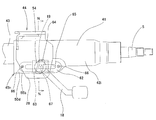
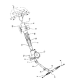
- the steering apparatus for an automobile transmits the rotation of the steering wheel 1 to the input shaft 3 of the steering gear unit 2, and pushes and pulls the pair of left and right tie rods 4 as the input shaft 3 rotates. And it is comprised so that a steering angle may be provided to a front wheel.
- the steering wheel 1 is supported and fixed at the rear end portion of the steering shaft 5.
- the steering shaft 5 is rotatably supported by the steering column 6 with the cylindrical steering column 6 inserted in the axial direction. ing.
- the front end portion of the steering shaft 5 is connected to the rear end portion of the intermediate shaft 8 via a universal joint 7, and the front end portion of the intermediate shaft 8 is connected to the input shaft 3 via another universal joint 9. Yes.
- a tilt mechanism for adjusting the vertical position of the steering wheel 1 and a telescopic mechanism for adjusting the front-rear position according to the physique and driving posture of the driver are widely known.
- the steering column 6 is supported with respect to the vehicle body 10 so as to be able to swing and swing around a pivot 11 installed in the width direction.
- the steering column 6 has a structure in which the outer column 13 and the inner column 14 are telescopically combined, and the steering shaft 5 has the outer shaft (outer tube) 15 and the inner.
- the shaft 16 and the shaft 16 are combined by spline engagement or the like so that the torque can be transmitted and the structure can be expanded and contracted.
- the displacement side bracket fixed to the portion near the rear end of the steering column 6 is supported so as to be able to be displaced in the vertical direction and the front-rear direction with respect to the fixed side bracket 12 supported on the vehicle body 10.
- the width direction refers to the width direction of the vehicle body and coincides with the left-right direction.
- the front-rear direction refers to the front-rear direction of the vehicle body.
- an electric power steering device is incorporated that reduces the force required to operate the steering wheel 1 using the electric motor 17 as an auxiliary power source.
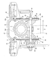
- a structure is required that allows the position of the steering wheel 1 to be adjusted or can be fixed to the adjusted position. 47 and 48, by rotating the hook-shaped member 19 by the adjusting lever 18 disclosed in Japanese Patent Laid-Open No. 2001-322552, the axial dimension of the cam device 20 is expanded and contracted, and at the same time, the cam member 21 A structure for swinging and displacing is described.
- the displacement-side bracket 22 fixed to the outer column 13a can be engaged with and disengaged from the fixed-side bracket 12a based on the expansion and contraction of the cam device 20. Further, based on the rocking displacement of the cam member 21, whether the inner column 14a can be moved relative to the outer column 13a is switched.
- the outer column 13a and the inner column 14a that constitute the steering column 6a of such a steering device are formed by pivoting an inner peripheral surface near the front end of the outer column 13a and an outer peripheral surface near the rear end of the inner column 14a. It is fitted over the entire circumference in a state where relative displacement in the direction is possible.
- the outer column main body is formed by an aluminum die casting method. Thereafter, the inner peripheral surface of the outer column main body is cut and finished.
- the displacement side bracket 22 is formed separately from the outer column 13a, and is integrally coupled and fixed by welding to a part of the outer column 13a.
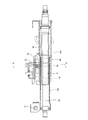
- the diameter from the inner peripheral surface of the inner peripheral surface of the outer column 13b which is disclosed in Japanese Patent Application Laid-Open No. 2008-302751, overlaps with the outer peripheral surface of the inner column 14a.
- a structure is shown in which ridges 23 projecting inward in the direction are formed, and the tips (radially inner ends) of these ridges 23 are brought into contact with the outer peripheral surface of the inner column 14a. With this structure, it is only necessary to perform cutting such as broaching on the tip of the raised portion 23 on the inner peripheral surface of the outer column 13b, so that the processing cost can be reduced.
- the outer column main body is formed by an aluminum die casting method, a hydroform method, or the like. Thereafter, forging and broaching are performed on a plurality of circumferential positions (11 in the figure) of the inner circumferential surface of the outer column main body overlapping with the outer circumferential surface of the inner column 14a. A raised portion 23 protruding radially inward from the inner peripheral surface is formed.
- the method of forming the outer column 13b and the method of forming the raised portion 23 are different, it is inevitable that processing takes time and processing costs increase.
- the contact between all the raised portions 23 and the outer peripheral surface of the inner column 14a It is desirable that the state is the same. However, it is troublesome to process the plurality of raised portions 23 to make the contact state the same.
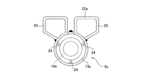
- FIG. 50 shows the structure of the steering column 6c disclosed in Japanese Patent Laid-Open No. 2008-302751.
- the outer column 13c constituting the steering column 6c is formed in a cylindrical shape by bending a plate-shaped material and welding circumferential edges (upper edges in FIG. 50) to each other.
- support claws 24 are formed at three positions in the circumferential direction on the inner peripheral surface of the outer column 13c that face the outer peripheral surface of the inner column 14a in the assembled state. These support claws 24 are formed by pressing a part of the outer column 13c and bending this part radially inward from the inner peripheral surface of the outer column 13c.
- a displacement side bracket 22a is provided on a part of the outer peripheral surface of the outer column 13c in the axial direction.
- the displacement-side bracket 22a is formed by bending the same plate-like material as that forming the outer column 13c, with one end edge connected to the outer peripheral surface of the outer column 13c, and welding the other end edge to the outer peripheral surface. It is constituted by a pair of left and right sandwiched portions 25.
- the support claw portions 24 are formed at substantially equal intervals at three locations in the circumferential direction. For this reason, the process for making the contact state of the front-end edge of all the support nail
- the support claw portion 24 has a cantilever-like structure, there is a problem that it is difficult to ensure rigidity for stably supporting the inner column 14a on the inner diameter side of the outer column 13c.
- a general telescopic steering device when the position of the steering wheel 1 is adjusted, the adjusting lever 18 is operated in a predetermined direction to reduce the frictional force acting between the fixed side bracket 12a and the displacement side bracket 22. .
- the adjusting lever 18 is operated in the direction opposite to the predetermined direction to increase the frictional force between these brackets.
- the number of friction surfaces is increased to increase the friction area. It is preferable.
- Japanese Patent Application Laid-Open Nos. 2008-100597, 10-35511, 2007-69821, 2011-5896, and Japanese Utility Model Publication No. 62-19483 include a plurality of friction members. A structure that increases the number of friction surfaces by overlapping is described.
- the displacement-side bracket 22b has a longitudinally long hole 29 extending in the axial direction of the steering column 6d for inserting the flange-shaped member 19, and the displacement-side bracket 22b in the left-right direction (width direction). It is provided in a penetrating state.
- the fixed bracket 12a is formed by coupling and fixing an upper bracket element 26 and a lower bracket element 27, each of which is formed by bending a metal plate.
- the upper bracket element 26 is supported on the vehicle body side by a well-known structure so as to be able to drop forward during a secondary collision.
- the lower bracket element 27 includes a pair of left and right support plate portions 28 provided in a state of being separated in the width direction.
- An interval D between the inner side surfaces (side surfaces facing each other) of these support plate portions 28 is substantially matched with an interval (width of the displacement side bracket 22b) W of the outer side surface of the displacement side bracket 22b (D ⁇ W).
- a partial arc-shaped vertical elongated hole 30 extending long in the vertical direction around the pivot 11 for inserting the flange-shaped member 19 is formed. ing.
- a plurality of first friction plates 31 and second friction plates 32 are disposed on the outer surface portion of the support plate portion 28.
- a first long hole 33 is formed in the first friction plate 31, and a second long hole 34 is formed in the second friction plate 32.
- the end portion of the first friction plate 31 is attached to the outer surface of the upper end portion of the support plate portion 28 by the first set screw 35, and the end portion of the second friction plate 32 is attached to the outer surface of the front end portion of the displacement side bracket 22b by the second set screw 36.
- the first friction plate 31 is prevented from being displaced in the length direction of the first long hole 33. ing.
- the first friction plate 31 and the second friction plate 32 are arranged on the outer surface of the support plate portion 28 so as to be alternately stacked.
- the eaves member 19 is inserted through the longitudinal slot 29, the vertical slot 30, the first slot 33, and the second slot 34.
- An flange portion 38 having an outward flange shape is formed at the base end portion (the right end portion in FIG. 52) of the flange portion 37 of the flange member 19.
- the engagement convex portion 39 having an oval cross section formed in the portion near the base end of the flange portion 37 is displaced into one of the vertical elongated holes 30 (to the right in FIG. 52) along the vertical elongated holes 30. Only (elevation) is freely engaged.
- first friction plate 31 and the second friction plate disposed on the outer plate portion 28 and the outer surface portion of the support plate portion 28 on the other side (left side in FIG. 52) near the tip of the intermediate portion of the flange portion 37.
- a pressing plate 40 is fitted on a portion protruding from 32, and a pressing cam device 20 is provided.
- the cam device 20 and the hook-shaped member 19 constitute a pressing device.
- the cam device expands or contracts the axial dimension T based on the operation of the adjustment lever 18, and its structure is well known.
- the adjustment lever 18 when adjusting the position of the steering wheel 1, the adjustment lever 18 is rotated in the direction opposite to the predetermined direction to reduce the axial dimension T of the cam device 20, The space
- 10-512825 proposes a structure in which a buffer sleeve is provided in a state of surrounding a long hole in the front-rear direction of the displacement side bracket.
- a buffer sleeve is provided in a state of surrounding a long hole in the front-rear direction of the displacement side bracket.
- these structures can be independently incorporated into the telescopic steering apparatus, it is inevitable that the assembling work becomes complicated and the cost increases.
- Japanese Patent Application Laid-Open No. 2006-255785 discloses that a bulging portion is formed in an axially intermediate portion of a hollow tubular material using a hydroforming method.
- a method for manufacturing a steering column is disclosed in which a through hole is formed in the side wall portion of the bulge and the bulging portion serves as a column bracket.
- the present invention provides a telescopic steering device that can stably hold an inner column on the inner diameter side of an outer column and can obtain stable operability of the adjusting lever without increasing the operating force applied to the adjusting lever.
- the purpose is to realize the structure of the steering column device.
- the present invention can increase the holding force for holding the steering wheel at a position after the adjustment, and if necessary, the driver can feel uncomfortable even when the front / rear position of the steering wheel is moved to the adjustment limit position.
- An object of the present invention is to realize a structure of a steering column device that can prevent discomfort and can be easily assembled and reduced in cost.
- the present invention relates to a steering column device for a telescopic steering device.
- the steering column device of the present invention is It has at least a part in which the inner diameter in the axial direction can be expanded and contracted, and a support part formed at three or more locations in the circumferential direction on the inner peripheral surface, and the hollow tube including the support part is radially outward
- a cylindrical outer column obtained by bulging and an outer peripheral surface that abuts the support portion at three or more locations in the circumferential direction, and is axially moved by the support portion on the inner diameter side of the outer column.
- a steering column that includes a cylindrical inner column that is fitted and supported so as to be capable of displacement of A portion fixed to the vehicle body side, a pair of support plate portions sandwiched from both sides in the width direction by a portion fixed to the vehicle body side and supported by the portion fixed to the vehicle body side and capable of expanding and contracting the inner diameter;
- a fixed side bracket comprising a vehicle body side through hole formed at a position where the pair of support plate portions are aligned with each other;
- a pair of sandwiched portions obtained by bulging and forming integrally with the outer column and sandwiched between the pair of support plate portions, and formed in the sandwiched portion, are long in the axial direction of the outer column.
- a displacement side bracket comprising a column side through hole; A flange-like member disposed in the width direction in a state of being inserted through the vehicle body side through hole and the column side through hole; and by the rotation of the bowl-like member, the distance between the pair of support plate portions A mechanism for expanding and contracting, An adjustment lever provided at a base end portion of the hook-shaped member for rotating the hook-shaped member; It is characterized by providing.
- the outer column is disposed behind the inner column, and one end of the displacement side bracket is connected to the pair of sandwiched portions, and the pair of sandwiched portions are arranged in a direction approaching each other in the width direction.
- the pair of inclined portions further includes a pair of inclined portions that extend from each other and the other ends are continuous via a continuous portion, and are aligned with respect to the axial direction of the column side through hole and the outer column. It is preferable to adopt a structure in which the angle formed by the support plate portion and the direction in which the clamped portion is pressed increases from the front toward the rear.
- the outer column is disposed behind the inner column
- the displacement-side bracket further includes a bottom portion that connects the pair of sandwiched portions in the width direction, and the width of the bottom portion It is preferable to adopt a structure in which a long hole in the axial direction is formed in the middle portion in the direction.
- the displacement side bracket further includes a bottom portion that connects the pair of sandwiched portions with respect to the width direction, and one of the sandwiched portions is disposed at an axial rear end of the displacement side bracket. It is preferable to adopt a structure in which a long hole is formed from a part to the other sandwiched part through the bottom part.
- a structure in which a long column long hole in the axial direction of the outer column is formed at a position where at least a part of the outer column is aligned with the column side through hole in the axial direction is preferable to take.
- the column long hole passes through the center axis of the inscribed circle of the support portion of the outer column, and more than a virtual plane orthogonal to the pair of support plate portions of the fixed bracket. It is preferable to adopt a structure formed on the displacement side bracket side with respect to the circumferential direction.
- the displacement side bracket further includes a bottom portion that connects the pair of sandwiched portions with respect to the width direction, and the axial rear end of the bottom portion and the outer peripheral surface of the outer column are formed by a rear end side continuous portion. It is preferable to adopt a structure in which the positions of the rear end portions of the column long holes in the axial direction are continuous with respect to the rear end side continuous portion.
- the support portion has a shortest axial dimension of a portion where the outer column and the inner column overlap each other in the radial direction, and the support portion has an inner circumferential surface of the outer column. It is preferable to adopt a structure that is aligned with the overlapping portion and provided at two positions spaced apart in the axial direction of the outer column.
- the support portion is positioned on the inner peripheral surface of the outer column, the position close to the tip of the displacement side bracket and the axial direction of the outer column, and the position near the rear end of the displacement side bracket. It is preferable to adopt a structure provided at two positions aligned with respect to the axial direction of the outer column.
- the displacement side A structure in which the first friction plates supported by the brackets and the second friction plates supported by the hook-shaped members in an interlocking manner with the movement of the hook-shaped members are alternately arranged. It is preferable to take.
- the steering column device of the aspect additionally applied is similar to the steering column device of the above aspect in that the steering column, the displacement side bracket, the first longitudinal longitudinal hole, the support bracket (fixed side) Bracket), a first through hole, a first friction member, a second longitudinal longitudinal hole, a second friction member, a second through hole, and a pressing device provided with a hook-like member.
- the inner column holding structure (the structure of the support portion) by the outer column and the outer column is not limited to the above-described mode.
- the outer column and the displacement side bracket do not have to be integrated, and need not be obtained by bulging molding.
- the first longitudinal longitudinal hole is formed in the displacement side bracket and is long in the axial direction of the steering column.
- the support bracket includes a pair of left and right support plate portions provided in a state where the displacement side bracket is sandwiched from both sides in the width direction, and is supported on the vehicle body side.
- the first through hole is formed in a portion that matches the support plate portion and a portion that matches a part of the first longitudinal longitudinal hole.
- the first friction member is supported by a part of the displacement side bracket so as to be able to be displaced in synchronization with the displacement side bracket.
- the second longitudinal longitudinal hole is formed in a portion of the first friction member aligned with the first longitudinal longitudinal hole, and is long in the axial direction of the steering column.
- the second friction member is sandwiched between the outer surface of the displacement side bracket and the first friction member.
- the second through hole is formed in a part of the second friction member that is aligned with a part of the second longitudinal longitudinal hole.
- the pressing device includes a hook-like member that is inserted through the first through hole, the first and second longitudinal longitudinal holes, and the second through-hole, and both ends of the hook-like member. It is comprised including a pair of press part provided in the part protruded from the outer surface. Then, the first and second friction members and the support plate portion are pressed toward the outer surface of the displacement side bracket. Further, the hook-like member is inserted through the second through hole in a state in which the hook-like member can be displaced in the axial direction and the displacement in the direction other than the axial direction is substantially prevented.
- the first friction member includes a first friction plate portion, a connecting plate portion, and a locking portion.
- the first friction plate is sandwiched between the inner surface of the support plate and the second friction member.
- the connecting plate portion is bent from the edge of the first friction plate portion toward the center in the width direction of the displacement side bracket.
- locking part is a bowl shape bent in the direction of the 1st friction board part from the front-end
- a locking hole is provided in the intermediate portion in the width direction of the displacement side bracket. The first friction member is engaged with the displacement-side bracket in a state where the engagement portion is engaged with the edge in the width direction of the engagement hole and the connecting plate portion is overlapped with the displacement-side bracket. It is assembled.
- a holding recess is provided in a portion surrounding the second longitudinal longitudinal hole on the outer surface of the first friction member.
- a buffer sleeve made of an elastic material such as rubber or vinyl or the like and provided with a third long longitudinal longitudinal hole in the axial direction of the steering column is held in the holding recess.
- the rear end portion of the third front-rear direction long hole is closer to the front portion than the rear end portion of the second front-rear direction long hole, and the front end portion of the third front-rear direction long hole is from the front end portion of the second front-rear direction long hole. Also place them in the rear part.
- the second friction member has a flat plate-like second friction plate portion in which a second through hole is formed and a shape viewed from the side, bent outward in the width direction from the upper end portion of the second friction plate portion. Is provided with a corrugated engagement plate portion. Further, an engagement groove portion that is long in the axial direction of the steering column is provided between the upper partition plate portion that partitions the upper end portion of the holding recess and the lower surface of the connecting plate portion. Then, the engaging plate portion is engaged with the engaging groove portion in a state in which the displacement in the axial direction is possible and the displacement in the vertical direction perpendicular to the axial direction is prevented.
- the first friction member when it is necessary to particularly increase the holding force for holding the steering wheel at the adjusted position, is configured by combining a plurality of first friction member elements.
- Each of the first friction member elements is supported by a part of the displacement side bracket so as to be able to be displaced in synchronization with the displacement side bracket.
- the first friction plate portions constituting the first friction member element are separated from each other in the axial direction of the flange-shaped member, and the connecting plate portions and the flange portions are overlapped with each other.
- one or more second friction members are arranged between the first friction plate portions of the first friction member elements, the first friction plate portions of any of the first friction member elements, and the outer side of the displacement side bracket. It is sandwiched between at least one portion between the portion between the side surface and the portion between the first friction plate portion of any of the first friction member elements and the inner surface of the support plate portion.
- the first and second friction members are placed between both outer side surfaces of the displacement-side bracket and inner side surfaces of the two support plate portions.
- One set is provided.
- the material and manufacturing method of the first friction member are not particularly limited as long as the required strength and friction coefficient can be obtained.
- the first friction member can be manufactured by cutting an extruded material or a drawing material made of a light alloy such as an aluminum alloy into a predetermined length, and further performing a trimming process for removing unnecessary portions.
- the first friction member can be made by bending an intermediate material obtained by stamping and forming a metal plate such as an iron-based alloy plate such as a carbon steel plate or a stainless steel plate.
- a pair of bent raised portions are formed at both front and rear end portions of the holding concave portion so as to block at least a part of the front and rear end openings of the holding concave portion, and the bent concave portions are held by the holding concave portion.
- the buffer sleeve is sandwiched from both front and rear sides to prevent the buffer sleeve from shifting in the front-rear direction with respect to the first friction member.
- the buffer sleeve can be bonded to the inner surface of the holding recess by bonding or the like.
- an outer column including a support portion for supporting the inner column and a displacement side bracket provided integrally with the outer column are integrally formed by bulging molding such as a hydroforming method. ing. For this reason, even when the support portion is composed of a plurality of (three or more) raised portions, the processing cost can be reduced, and these support portions can have high rigidity. In addition, a troublesome fixing work such as welding by disposing the displacement-side bracket and the outer column separately becomes unnecessary.
- the support portion and the outer peripheral surface of the inner column that overlaps the support portion are supported in contact with each other at three locations in the circumferential direction, the support portion is surely applied to the outer peripheral surface of the inner column.
- processing for equalizing the contact state at all contact locations is facilitated.
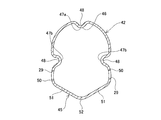
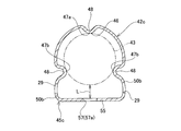
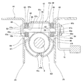
- FIG. 1 is a cross-sectional view showing a first example of the first embodiment of the present invention.
- FIG. 2 is a side view showing only the outer column in the first example of the first embodiment.
- 3 is a cross-sectional view taken along the line AA in FIG.
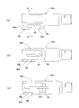
- FIG. 4 is a side view showing only the outer column in the second example of the first embodiment of the present invention.
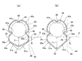
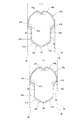
- 5A and 5B are a BB cross-sectional view (a) and a CC cross-sectional view (b) in FIG.
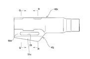
- FIG. 6 is a side view (a) and a bottom view (b) showing only the outer column for the third example of the first embodiment of the present invention.
- FIG. 7 is a sectional view taken along the line DD of FIG. FIG.
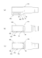
- FIG. 8 is a side view (a) which takes out only an outer column about the 4th example of 1st Embodiment of this invention, and shows the bottom view (b) which shows the 1st example of the long hole formed in the bottom part of the outer column. ) And a bottom view (c) showing a second example of the long hole.
- FIG. 9 is a cross-sectional view taken along line EE of FIG.
- FIG. 10 is a side view (a) and a bottom view (b) showing only the outer column taken out for the fifth example of the first embodiment of the present invention.
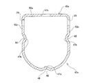
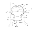
- FIG. 11 is a plan view (a) and a side view (b) showing only the outer column for the sixth example of the first embodiment of the present invention.
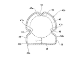
- FIG. 12 is a cross-sectional view taken along the line FF in FIG.
- FIG. 13 is a cross-sectional view similar to FIG. 1 for the sixth example of the first embodiment of the present invention.
- FIG. 14 is a side view showing only the outer column in the seventh example of the first embodiment of the present invention.
- 15 is a cross-sectional view taken along the line GG in FIG.
- FIG. 16 is a side view showing only the outer column in the eighth example of the first embodiment of the present invention.
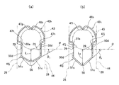
- FIG. 17 is a cross-sectional view taken along line HH in FIG. 16 (a) and a cross-sectional view taken along line II (b).
- FIG. 18 is a side view showing only the outer column in the ninth example of the first embodiment of the present invention.
- FIG. 19 is a JJ sectional view (a) and a KK sectional view (b) of FIG.
- FIG. 20 is a partial side view showing a tenth example of the first embodiment of the present invention.
- FIG. 21 is a side view showing only the outer column in the tenth example of the first embodiment of the present invention.
- 22 is an LL sectional view (a) and an MM sectional view (b) of FIG.
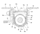
- FIG. 23 is a sectional view taken along line NN in FIG. 24 is a cross-sectional view similar to FIG. 23, showing an eleventh example of the first embodiment of the present invention.
- FIG. 25 is a side view showing only the outer column taken out from the twelfth example of the first embodiment of the present invention.
- FIG. 26 is a cross-sectional view taken along line OO in FIG. 25 (a) and a cross-sectional view taken along line PP (b).
- FIG. 27 is a side view showing only the outer column in the thirteenth example of the first embodiment of the present invention.
- 28A and 28B are a QQ sectional view (a) and an RR sectional view (b) in FIG.
- FIG. 29 is a view similar to FIG. 1 and showing a fourteenth example of the first embodiment of the present invention.
- FIG. 30 is a view similar to FIG. 1, showing a fifteenth example of the first embodiment of the present invention.
- FIG. 31 is a side view (a) showing only the outer column with respect to the sixteenth example of the first embodiment of the present invention, and a bottom view (b) showing a first example of a long hole formed in the bottom of the outer column. ) And a bottom view (c) showing a second example of the long hole.
- 32 is a cross-sectional view taken along the line SS of FIG.
- FIG. 33 is a side view (a) showing only the outer column in the seventeenth example of the first embodiment of the present invention, and a rear end connecting the rear end portion of the displacement side bracket and the outer peripheral surface of the outer column.
- FIG. 34 is a side view showing only the outer column with respect to the eighteenth example of the first embodiment of the present invention.
- 35 is a TT cross-sectional view of FIG.
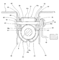
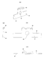
- FIG. 36 is a cross-sectional view showing a first example of the second embodiment of the present invention.
- FIG. 37 is an exploded perspective view of main parts of a second example of the second embodiment of the present invention.
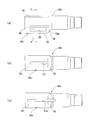
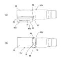
- FIG. 38 is a diagram showing the ⁇ part of FIG. 36 in the order of the assembly process.
- FIG. 34 is a side view showing only the outer column with respect to the eighteenth example of the first embodiment of the present invention.
- 35 is a TT cross-sectional view of FIG.
- FIG. 36 is a cross-sectional view showing a first example of the second embodiment of the present invention.
- FIG. 37 is an exploded perspective view of main parts of a second example of the second embodiment of the present invention.
- FIG. 38 is a diagram showing the ⁇ part of FIG. 36 in the order of
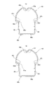
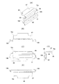
- FIG. 39 is a perspective view (A) of the first friction member, an end view (B) seen from the front-rear direction, an inner side view (C) seen from the left side of (B), and the same as seen from the right side.
- FIG. 40 is a perspective view (A) of the second friction member, an end view (B) seen from the front-rear direction, an outer side view (C) seen from the right side of (B), and a lower part of (C). It is the bottom view (D) seen from.
- FIG. 41 is a side view of the buffer sleeve.
- FIG. 42 is an exploded perspective view of main parts of a second example of the second embodiment of the present invention.
- FIG. 43 is a perspective view (A) of the first friction member, a plan view (B), an outer side view (C) viewed from below (B), and a front-rear direction viewed from the right side of (C). It is an end view (D) and a bottom view (E) as seen from below.
- FIG. 44 is a view similar to FIG. 38C, showing a third example of the second embodiment of the present invention.
- FIG. 45 is a view similar to FIG. 36, showing a fourth example of the second embodiment of the present invention.
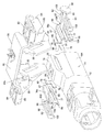
- FIG. 46 is a partially cutaway side view showing an example of a telescopic steering device for an automobile.
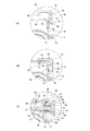
- FIG. 47 is a longitudinal sectional side view showing a first example of a conventional steering column device.
- FIG. 48 is an enlarged UU sectional view of FIG.
- FIG. 49 is a sectional view similar to FIG. 48, showing a second example of a conventional steering column device.
- FIG. 50 is a front view showing only the outer column in a third example of the conventional steering column device.
- FIG. 51 is a partially cutaway side view showing a fourth example of a conventional steering column device.
- 52 is a cross-sectional view taken along the line VV of FIG.
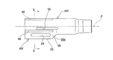
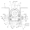
- FIG. 1 to 3 show a first example of the first embodiment of the present invention.
- the feature of the steering column device of the present invention is that the structure of the outer column constituting the steering column is devised.
- the present invention can be applied to the structure of a telescopic steering device that includes a tilt mechanism for adjusting the vertical position in addition to a telescopic mechanism for adjusting the front-rear position of the steering wheel 1. Since the structure other than the characteristic part of the present invention is substantially the same as the structure of the conventional telescopic steering device and the steering column device applied thereto, the illustration and description of the parts configured in the same manner as in the past are omitted or omitted. In the following, the description will be focused on the characteristic portions of this example.
- the telescopic steering device of this example includes a steering shaft 5, a steering column 41, a fixed side bracket 44, a displacement side bracket 45, a bowl-shaped member 19, and an adjustment lever 18.
- the steering shaft 5 is mounted with the steering wheel 1 at the rear end portion thereof, and is rotatably supported inside the steering column 41.
- the steering column 41 includes an outer column 42 and an inner column 43.
- the outer column 42 is an upper column on the steering wheel 1 side
- the inner column 43 is a lower column far from the steering wheel 1.
- the outer column 42 has a cylindrical shape in which at least a part of the inner diameter in the axial direction can be elastically expanded and contracted, and the inner column 43 is fitted and supported on the inner diameter side of the outer column 42 so as to be capable of axial displacement.
- a support 46 is provided.
- the support portion 46 protrudes radially inward from the inner peripheral surface of the inner peripheral surface of the outer column 42 at three positions at equal intervals in the circumferential direction of a portion overlapping the inner column 43 in the radial direction. It is composed of raised portions 47a and 47b formed in a state.
- a recess 48 that is recessed radially inward from the outer peripheral surface is formed in the outer peripheral surface of the outer column 42 at a position that aligns with the raised portions 47a and 47b in the circumferential direction.
- the leading edges (radially inner edges) of these raised portions 47 a and 47 b are in contact with the outer peripheral surface of the inner column 43.
- the number of 47a, 47b is preferably three in this example. However, in consideration of a balance such as processing cost, the number of the raised portions 47a and 47b can be more than three (for example, two on each of the left and right, for a total of four). Further, the positions where the raised portions 47 a and 47 b are formed are not limited to the circumferentially equidistant positions on the inner peripheral surface of the outer column 42. However, it is preferable not to be biased toward the semicircular side but to be distributed in a range exceeding the semicircular circumference.
- the outer column 42 (including the support portion 46) applies a hydraulic pressure (for example, water pressure) to the inner peripheral surface of a metal tube that is a hollow member made of a steel plate or an aluminum alloy, and causes the metal tube to radially outward. This is swelled and molded by the hydroform method of plastic deformation.
- a hydraulic pressure for example, water pressure
- a metal tube as a material is set in a mold having an inner surface shape that matches the outer surface shape of the outer column 42 to be expanded, Both ends of the metal tube are closed with a shaft pushing tool, etc., and a high hydraulic pressure is applied to the inside of the metal tube to expand the diameter of the metal tube radially outward until it is in close contact with the inner surface of the mold cavity.
- the outer column 42 is formed.
- cutting or pressing may be performed on the tip portions of the raised portions 47a and 47b constituting the support portion 46.
- the method of bulging the outer column 42 is not limited to the hydroforming method, and any bulging molding means such as press processing, bulge processing, vacuum molding, air blow molding, and explosion molding can be employed. .
- the fixed-side bracket 44 is provided on the vehicle body 10 or a portion fixed to the vehicle body 10, and a pair of left and right support plates sandwiching a portion 49 of the outer column 42 whose inner diameter can be expanded and contracted from both sides in the width direction.
- the unit 28 is provided.
- the displacement side bracket 45 is formed integrally with the outer column 42 by a hydroform method, and is sandwiched between a pair of support plate portions 28 and can be expanded and contracted in the width direction. And a pair of inclined portions 51.
- the sandwiched portion 50 has one end continuous to the lower end of the raised portion 47b formed on the lower side of the raised portions 47a and 47b of the outer column 42, and is formed substantially parallel to the pair of support plate portions 28. ing.
- column-side through holes (longitudinal direction long holes) 29 that are long in the axial direction of the outer column 42 are formed at positions where these sandwiched portions 50 are aligned with each other.
- the inclined portion 51 has one end connected to the other end of the sandwiched portion 50 and extends so as to approach each other in the width direction (left-right direction in FIG. 1) (in a diagonally downward direction in FIG. 1). The other end of each is made continuous.
- the hook-shaped member 19 is arranged in the width direction in a state where the vehicle body side through hole (not shown) formed at the position where the support plate portion 28 is aligned with the column side through hole 29 of the sandwiched portion 50 is inserted. Has been established. Moreover, the head 53 which is a press part is provided in the end (left end of FIG. 1) of the bowl-shaped member 19. As shown in FIG. Then, at the other end (right side in FIG. 1) of the flange-shaped member 19, a holding nut 54 that is a pressing member is provided at a portion protruding from the outer side surface (right side surface in FIG. 1) of the support plate portion 28 of the fixed side bracket 44. It is screwed.
- the base end portion of the adjusting lever 18 is coupled and fixed to the holding nut 54. Therefore, based on the operation of the adjusting lever 18, the hook-shaped member 19 is rotated, and at the same time, the holding nut 54 is rotated, and the interval in the width direction between the holding nut 54 and the head 53 can be changed (expanded / reduced). In this case, the interval between the support plate portions 28 can be enlarged or reduced.
- the hook-shaped member 19 and the holding nut 54 are combined, and the cam device is combined with the hook-shaped member 19 as in the conventional case.
- Other structures can also be employed.
- the adjustment lever 18 When adjusting the position of the steering wheel 1 in the front-rear direction, the adjustment lever 18 is rotated in a predetermined direction to widen the interval in the width direction between the holding nut 54 and the head 53. Thereby, the space
- the surface pressure of the abutting part decreases or disappears. Accordingly, the surface pressure of the fitting portion between the support portion 46 of the outer column 42 and the outer peripheral surface of the inner column 43 is reduced or lost, and the outer column 42 and the inner column 43 are relatively relative to each other in the axial direction (front-rear direction). It will be in a displaceable state. As a result, the position of the steering wheel 1 in the front-rear direction can be adjusted.
- the adjusting lever 18 is rotated in the direction opposite to the predetermined direction, the interval in the width direction between the holding nut 54 and the head 53 is reduced.
- interval of the inner surface of the support plate part 28 shrinks, and the surface pressure of the contact part of the inner surface of these support plate parts 28 and the outer surface of the to-be-clamped part 50 becomes large. Accordingly, the surface pressure of the fitting portion between the support portion 46 of the outer column 42 and the outer peripheral surface of the inner column 43 increases. As a result, the steering wheel 1 is supported at the adjusted position.
- the shape of the column-side through hole of the displacement side bracket formed integrally with the outer column is a long hole ( Instead of a long hole in the front-rear direction), a round hole through which the bowl-shaped member can be inserted is used.
- the outer column 42 including the support portion 46 and the displacement side bracket 45 provided integrally with the outer column 42 are formed by the hydroform method. For this reason, the processing cost can be reduced as compared with the conventional structure.
- the support portion 46 provided on the inner peripheral surface of the outer column 42 and the outer peripheral surface of the inner column 43 overlapping the support portion 46 are brought into contact with each other only at three locations in the circumferential direction. For this reason, the raised portions 47 a and 47 b can be reliably brought into contact with the outer peripheral surface of the inner column 43 without increasing the processing accuracy of the raised portions 47 a and 47 b constituting the support portion 46. If the processing accuracy of the support portion 46 is not sufficient by the hydroform method alone, cutting is applied to the tip portions of the raised portions 47a and 47b of the support portion 46. However, in the case of this example, the number of these raised portions 47a and 47b is only three.
- the diameters of the inscribed circles of the three raised portions 47a and 47b are the same in the axial direction, so that finishing work such as cutting and pressing is not very troublesome.
- the raised portions 47a and 47b constituting the support portion 46 are formed in a mountain shape by a hydroforming method. For this reason, compared with the structure shown in FIG. 50, the rigidity for supporting the inner column 43 can be made high.
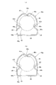
- FIGSecond Example of First Embodiment 4 and 5 show a second example of the first embodiment of the present invention.
- the outer column 42 a is disposed behind the inner column 43 as in the first example.
- column-side through holes 29 that are long in the axial direction are formed at positions where the clamped portions 50a of the displacement-side bracket 45a provided integrally with the outer column 42a are aligned with each other.
- the angle to be formed becomes larger as it becomes rearward (right side in FIG. 4).
- the angle ⁇ 2 formed is such that the inclined portion 51a of the displacement side bracket 45a and the support plate portion 28 are sandwiched at the position aligned with the front end portion of the column side through hole 29 in the axial direction. It is larger than an angle ⁇ 1 (see FIG. 5A) formed by a direction ⁇ in which 50a is pressed (clamped) ( ⁇ 2 > ⁇ 1 ).
- the angle formed by the inclined portion 51a of the displacement side bracket 45a and the direction ⁇ in which the support plate portion 28 presses (holds) the sandwiched portion 50a continuously changes from the front to the rear.
- the distance between the inner peripheral surface of the continuous portion 52 of the inclined portion 51a and the outer peripheral surface of the inner column 43 at a position aligned with the column side through hole 29 in the axial direction increases as it goes rearward. That is, the distance L 2 between the inner peripheral surface of the continuous portion 52 and the lower end of the outer peripheral surface of the inner column 43 at a position aligned with the rear end portion of the column side through hole 29 in the axial direction (see FIG. 5B). ) Is greater than the distance L 1 between the inner peripheral surface of the continuous portion 52 and the lower end of the outer peripheral surface of the inner column 43 at a position aligned with the front end portion of the column side through hole 29 (see FIG. 5A). Large (L 1 ⁇ L 2 ).
- the rigidity in the width direction of the sandwiched portion 50a of the displacement side bracket 45a is lowered as it goes rearward. Therefore, stable operability can be obtained without greatly changing the operating force applied to the adjusting lever 18 by the length of the portion where the outer column 42a and the inner column 43 overlap in the axial direction. As a result, stable support rigidity (clamping force) can be imparted to the inner column 43.
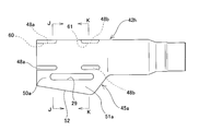
- FIG. 6 and 7 show a third example of the first embodiment of the present invention.
- the outer column 42 b is arranged behind the inner column 43.
- column-side through-holes 29 that are long in the axial direction are formed in portions where the clamped portions 50b of the displacement-side bracket 45b provided integrally with the outer column 42b are aligned with each other.
- one end (the lower end in FIG. 6) of these sandwiched portions 50 b is continuous in the width direction via a flat bottom portion 55.
- the rear end side of the bottom portion 55 is continuous in the axial direction with the outer peripheral surface of the outer column 42 b via the continuous portion 56.
- the distance L between the inner surface of the bottom 55 and the lower end of the outer peripheral surface of the inner column 43 at a position aligned with the pair of column side through holes 29 in the axial direction is constant in the axial direction.
- Other structures and operations are the same as in the first example of the first embodiment.
- FIG. 8 (b) or (c) show a fourth example of the first embodiment of the present invention.
- the outer column 42c constituting the steering column device of this example has the same basic structure as the outer column 42b of the third example of the first embodiment.
- the outer column 42c is positioned at the center in the width direction of the bottom 55 of the displacement-side bracket 45c so as to be aligned with at least the column-side through hole 29 in the axial direction. Long holes 57, 57a that are long in the axial direction are formed.
- the long hole 57 shown in FIG. 8 (b) has its axial position substantially coincided with the column side through hole 29.
- the dimension in the axial direction of the long hole 57a shown in FIG. 8C is larger than the dimension in the axial direction of the column side through hole 29 and the long hole 57. That is, the long hole 57a is continuous with the axial direction rear end of the bottom 55 and the outer peripheral surface of the outer column 42c from the front of the axial front end of the column side through hole 29 of the bottom 55 in the axial direction. To the outer peripheral surface of the outer column 42c.
- Such long holes 57 and 57a can also be formed simultaneously by the hydroforming method (see Japanese Patent Application Laid-Open No. 2006-255785).
- the elongated holes 57 and 57a are formed in the bottom 55 of the displacement side bracket 45c, thereby reducing the rigidity in the width direction of the bottom 55 and the sandwiched portion 50b.
- the long hole 57a is connected to the outer column 42c through a continuous portion 56 that continues from the bottom 55 to the rear end of the bottom 55 and the outer peripheral surface of the outer column 42c. If the outer peripheral surface is formed, the rigidity of the bottom 55 and the portion near the rear end of the sandwiched portion 50b can be sufficiently lowered.
- this example can be implemented in combination with each example of 1st Embodiment.
- the inclined portion 51 (51a) is a portion corresponding to the bottom portion 55.
- this example can be applied regardless of the support structure of the outer column and the inner column.
- Other structures and operations are the same as those of the first example and the second example of the first embodiment.
- FIG. 10 shows a fifth example of the first embodiment of the present invention.
- the outer column 42d constituting the steering column device of this example has the same basic structure as the outer column 42b of the third example of the first embodiment.
- the outer column 42d is disposed at the rear end of the displacement side bracket 45d in the axial direction (the front end of the continuous portion 56 connecting the axial rear end of the bottom 55 and the outer peripheral surface of the outer column 42d).
- a long hole 58 that is continuous in the width direction is formed from one sandwiched portion 50b through the bottom portion 55 to the other sandwiched portion 50b.
- the rigidity in the width direction of the rear end portion in the axial direction of the displacement side bracket 45d can be reduced. That is, since the continuous portion 56 exists at the axial rear end of the displacement side bracket 45d, the rigidity in the width direction is higher than that of the axial front end. Therefore, the long hole 58 is formed to reduce the rigidity in the width direction of the axial rear end of the displacement side bracket 45d. As a result, the tightening torque of the adjusting lever 18 required to fix the outer column 42d and the inner column 43 is increased regardless of the radial overlapping state (the axial dimension of the overlapping portion) between the outer column 42d and the inner column 43. The operability of the adjusting lever 18 is stabilized so as not to differ greatly.
- this example can be implemented in combination with each example of 1st Embodiment. Other structures and operations are the same as in the third example of the first embodiment.
- FIG. 11 to 13 show a sixth example of the first embodiment of the present invention.
- the displacement side bracket 45e constituting the steering column device of the present example is provided in a state of protruding upward from the front end portion of the outer column 42e.
- the displacement-side bracket 45e has a substantially symmetric structure with respect to the radial direction (vertical direction) with the displacement-side bracket 45c of the fourth example of the first embodiment, and a pair of left and right sandwiched plate portions 50c.
- the bottom part 55a is comprised.
- the sandwiched plate portions 50c are provided in a state of being continuous upward from the main body portion of the outer column 42e, and are parallel to each other. Moreover, the bottom part 55a is provided in the state which makes the one end edge (upper end edge of FIG. 12 and FIG. 13) of the to-be-clamped board part 50c continue in the width direction. Similarly to the fourth example of the first embodiment, the column-side through holes 29 that are long in the axial direction are formed in the portions of the clamped portion 50c of the displacement-side bracket 45e that are aligned with each other.
- a long hole 57b that is long in the axial direction is formed over the outer peripheral surface of the column 42e.
- this long hole 57b can also be made into the shape by which the front end side was plugged like the long hole 57 shown in FIG.8 (b) or the long hole 57a shown in FIG.8 (c).
- the structure of this example can also be implemented together with the structure of each example of the first embodiment.
- the outer column 42e constituting the steering column device of this example is assembled in a state as shown in FIG.
- the first embodiment of the first embodiment With regard to the operation for adjusting the position of the steering wheel 1 in the front-rear direction and the operation for fixing the steering wheel 1 at the position after the position adjustment in the assembled state, the first embodiment of the first embodiment. The operation is the same as that of the example apparatus.
- the displacement side bracket 45e is provided so as to protrude upward from the front end portion of the outer column 42e.
- the flange-shaped member 19 is not disposed below the front end portion of the outer column 42e, and the design of the structure that can prevent interference with the driver's knee or the like can be facilitated.
- Other structures and operations are the same as in the fourth example of the first embodiment.
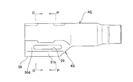
- the outer column 42f constituting the steering column device of the present example has the same basic structure as the outer column 42c of the fourth example of the first embodiment.
- the outer column 42f has an axial rear end portion (of the axial side of the outer column 42f) that is slightly rearward of the axial side center portion of the column side through hole 29 in the axial direction.
- a pair of column long holes 59 that are long in the axial direction are formed slightly behind the axial rear end of the bottom portion 55 and the front end portion of the continuous portion 56 that continues the outer peripheral surface of the outer column 42f.
- the front end positions in the axial direction of the column long holes 59 are not limited to the positions in this example, and the column long holes 59 can be formed to a position ahead of the front end of the column side through holes 29.
- the column long hole 59 passes through the center axis O 42f of the inscribed circle (the outer peripheral surface of the inner column 43) of the support portion 46 of the outer column 42f with respect to the circumferential direction of the outer column 42f.
- the column long holes 59 are formed at two positions in the circumferential direction of the outer column 42f.
- the positions or the number of the column long holes 59 are determined according to the outer column 42f. This is appropriately determined in consideration of the support rigidity (tightening force) of the inner column 43.
- the rigidity in the width direction of the displacement side bracket 45f at the position aligned with the column long hole 59 in the axial direction can be reduced.
- the rigidity in the width direction is higher than that at the front end portion in the axial direction. Therefore, in the case of this example, the position of the rear end portion of the column long hole 59 in the axial direction is slightly behind the continuous portion 56. For this reason, the rigidity regarding the width direction of the axial direction rear-end part of the displacement side bracket 45f can be made low.
- this example can be implemented in combination with each example of 1st Embodiment. Other structures and operations are the same as in the fourth example of the first embodiment.
- FIG. 16 and 17 show an eighth example of the first embodiment of the present invention.
- the outer column 42g constituting the steering column device of the present example has the same basic structure as the outer column 42c of the fourth example of the first embodiment.
- the support part 46a of the outer column 42g is constituted by a front support part 60 and a rear support part 61. Both the front support portion 60 and the rear support portion 61 contact the outer peripheral surface of the inner column 43 even when the axial dimension of the portion where the outer column 42g and the inner column 43 overlap in the radial direction is the shortest. It is provided at a position where it can touch.
- the front support portion 60 has a circumferential position that is aligned with respect to the axial direction from the front end portion of the outer column 42g to the front end portion of the column side through hole 29 of the displacement side bracket 45g on the inner peripheral surface of the outer column 42g. Consists of raised portions 47c and 47d formed at three positions at equal intervals in the direction protruding radially inward from the inner peripheral surface of the outer column 42g. In addition, a recess 48a that is recessed radially inward from the outer peripheral surface is formed at a position that aligns with the raised portions 47c and 47d in the circumferential direction on the outer peripheral surface of the outer column 42g.
- the rear support portion 61 is slightly rearward from the rear end portion of the column side through hole 29 from the portion near the rear end of the column side through hole 29 of the displacement side bracket 45g on the inner peripheral surface of the outer column 42g.
- the outer column 42g is projected radially inward at three circumferentially equidistant positions that are aligned with respect to the axial direction.
- the raised portions 47e and 47f are formed.
- a recess 48b that is recessed radially inward from the outer peripheral surface is formed at a position that aligns with the raised portions 47e and 47f in the circumferential direction on the outer peripheral surface of the outer column 42g.
- the portion between the front support portion 60 and the rear support portion 61 in the axial direction is not in contact with the outer peripheral surface of the inner column 43.
- the protruding portion and the concave portion are not formed in this portion, and the outer peripheral surface of the outer column 42g and the displacement side bracket 45g are directly continuous.
- the steering column device of this example regardless of the overlapping state in the radial direction between the outer column 42g and the inner column 43, the front support portion 60 and the rear support portion 61 that constitute the support portion 46a of the outer column 42g.
- the inner column 43 can be supported at the same two positions always in the axial direction. Therefore, even when a moment in a direction in which the central axes of the inner column 43 and the outer column 42g are inclined is applied between the inner column 43 and the outer column 42g in the vertical direction, for example, The inner column 43 can be stably supported by the rear support portion 61.
- this example can be implemented in combination with each example of 1st Embodiment. Other structures and operations are the same as in the fourth example of the first embodiment.
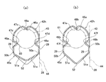
- FIG. 18 and 19 show a ninth example of the first embodiment of the present invention.
- the outer column 42h constituting the steering column device of the present example has the same basic structure as the outer column 42a of the second example of the first embodiment.
- the support part 46a of the outer column 42h is constituted by a front support part 60 and a rear support part 61.
- the front support part 60 and the rear support part 61 are provided at the same positions as in the structure of the eighth example of the first embodiment, and the shaft of the part where the outer column 42h and the inner column 43 overlap in the radial direction In the state where the directional dimension is the shortest, the front support part 60 and the rear support part 61 and the outer peripheral surface of the inner column 43 can contact each other.
- this example can be implemented in combination with each example of 1st Embodiment. Other structures and operations are the same as those of the second example and the eighth example of the first embodiment.
- [Tenth example of the first embodiment] 20 to 23 show a tenth example of the first embodiment of the present invention.
- the structure of the steering column device of this example is different from the device structure of each example of the first embodiment in that a first friction plate 62 and a second friction plate 63 are provided, and these friction plates 62, 63. Is different in that the structure of the displacement-side bracket 45h is devised.
- the outer column 42i constituting the steering column device of this example has a cylindrical shape in which at least a part of the inner diameter in the axial direction can be elastically expanded / contracted.
- a support portion 46b for fitting and supporting the inner column 43 on the inner diameter side so as to be capable of axial displacement is provided.
- the support portion 46b includes a front support portion 60a and a rear support portion 61a.
- the positions of the front support part 60a and the rear support part 61a in the axial direction are the same as the structure of the eighth example of the first embodiment.
- the front support portion 60a has a circumference at a position that is aligned in the axial direction from the front end portion of the outer column 42i to a portion near the front end of the column side through hole 29 of the displacement side bracket 45h on the inner peripheral surface of the outer column 42i. It is composed of raised portions 47g and 47h that are formed in a state of projecting radially inward from the inner peripheral surface at three positions at equal intervals in the direction.
- the protruding portion 47g is formed at one position on the inner peripheral surface above FIG. 22 (a).
- the raised portions 47h are formed at two positions shifted from the raised portion 23g at equal intervals in the circumferential direction (120 ° shifted in this example). The leading edges (radially inner edges) of these raised portions 47 g and 47 h are in contact with the outer peripheral surface of the inner column 43.
- the rear support portion 61a is slightly rearward from the rear end edge of the column side through hole 29 from a portion of the inner peripheral surface of the outer column 42i closer to the rear end of the column side through hole 29 of the displacement side bracket 45h.
- the outer column 42i protrudes inward in the radial direction at three positions at equal intervals in the circumferential direction that are aligned with respect to the axial direction.
- the raised portions 47i and 47j are formed.
- the raised portion 47i is formed at one position on the inner peripheral surface above FIG. 22 (b).
- the raised portions 47j are formed at two positions shifted from the raised portions 47i at equal intervals in the circumferential direction (120 ° in this example).
- leading edges (radially inner edges) of these raised portions 47 i and 47 j are in contact with the outer peripheral surface of the inner column 43.
- the portion between the front support portion 60a and the rear support portion 61a in the axial direction is not in contact with the outer peripheral surface of the inner column 43.
- the outer column 42 i has both end faces in the width direction (left-right direction in FIG. 23) of the outer peripheral surface of the outer column 42 i abutted against the inner surface of the support plate portion 28 of the fixed side bracket 44. Touching. In this way, the support rigidity in the width direction is increased, and the steering column 41 is less likely to vibrate in the width direction.
- the raised portions 47g, 47h (47i, 47j) constituting the front support portion 60a and the rear support portion 61a the raised portions 47h (47j) formed below the FIGS. 22 and 23 and the outer periphery of the inner column 43
- the surface is an angle ⁇ (30 ° in the case of this example) on the displacement side bracket 45h side (lower side in FIG. 23) with respect to a virtual plane ⁇ passing through the center O 43 of the inner column 43 and orthogonal to the support plate portion 28. ) Is in contact at a tilted position.
- the angle ⁇ is increased, that is, as the dimension in the width direction between the raised portions 47h (47j) formed in the lower part of FIG.
- the support rigidity in the vertical direction of the outer column 42i can be increased.
- the moldability of the displacement side bracket 45h can be improved.
- the angle ⁇ is excessively increased, the support rigidity in the width direction is lowered. Therefore, the magnitude of the angle ⁇ is appropriately determined in consideration of the support rigidity required in each direction, the thicknesses of the first friction plate 62 and the second friction plate 63, and the like.
- the displacement side bracket 45 h is provided in a state of projecting downward from the front end portion of the outer column 42 i, and accompanying the expansion and contraction in the width direction of the pair of support plate portions 28 constituting the fixed side bracket 44. And a pair of sandwiched portions 50d and a bottom portion 55b that can be expanded and contracted in the width direction.
- a vehicle body side through hole 64 that is long in the vertical direction and through which the flange member 19 can be inserted is formed at a position where the support plate portions 28 of the fixed side bracket 44 are aligned with each other.
- the sandwiched portion 50d has one end continuous from the lower ends of the raised portions 47h and 47j formed below the raised portions 47g and 47h (47i and 47j) of the outer column 42i, and a pair of support plate portions. 28 is formed substantially in parallel.
- the portion between the front support portion 60a and the rear support portion 61a in the axial direction of the outer column 42i has both ends in the width direction (the left-right direction in FIGS. 22 and 23) of the outer column 42i inside the width direction. And is continued to the upper edge of the sandwiched plate portion 50d.
- the dimension W related to the width direction of the inner side surfaces in the width direction of the support plate portion 28 is the length D of the outer side surfaces in the width direction (left-right direction in FIG.
- the bottom portion 55b is provided in a state where the lower end edges of the sandwiched portion 50d are continuous. Therefore, the displacement-side bracket 45h has a box shape in which the lower side and the front side are opened.
- a first friction plate 62 and a second friction plate 63 are disposed between the inner side surface in the width direction of the support plate portion 28 and the outer side surface in the width direction of the sandwiched portion 50d.
- one first friction plate 62 and one second friction plate 63 are arranged, and the second friction plate 63 is arranged in the width direction of the first friction plate 62. Arranged to be inside.
- the positional relationship regarding the width direction of these friction plates 62 and 63 can also be reversed to the case of this example.
- the first friction plate 62 is a plate-like member that is made of an iron alloy or a light alloy such as an aluminum alloy or a magnesium alloy and that is long in the front-rear direction. Also, the first friction plate 62, which is long in the front-rear direction, can be inserted into the flange-like member 19 at a position aligned with at least the column-side through hole 29 of the sandwiched portion 50d of the first friction plate 62. Is forming. In the first friction plate 62, the rear end portion and the front end portion can be displaced in the width direction by the guide pin 66 on the sandwiched portion 50d, but the displacement in the axial direction and the vertical direction is prevented. I support it. That is, the first friction plate 62 is supported with respect to the displacement side column 45h so as to be movable in conjunction with the displacement side column 45h in the axial direction and the vertical direction.
- the second friction plate 63 is a plate-like member made of an iron alloy or a light alloy such as an aluminum alloy or a magnesium alloy. Further, a second friction plate side through-hole 67 is formed at the center position of the second friction plate 63 so that the flange-shaped member 19 can be inserted so as not to rattle. That is, in a state in which the flange-shaped member 19 is inserted into the second friction plate-side through hole 67, the second friction plate 63 moves in conjunction with the flange-shaped member 19 and the shaft of the flange-shaped member 19. Directional displacement is possible.
- the outer column 42i, the first friction plate 62, and the second friction plate 63 constituting the steering column device of this example are assembled in a state as shown in FIG. 23, when adjusting the position of the steering wheel 1 in the front-rear direction, the adjustment lever 18 is rotated in a predetermined direction, and one end (see FIG. 23, the space in the width direction between the holding nut 54, which is a pressing member provided at the right end), and the head 53, which is a pressing member provided at the other end of the flange-shaped member 19, is increased. Thereby, the space
- the surface pressure at the contact portion between these members is reduced or lost.
- the surface pressure of the fitting portion between the support portion 46b (front support portion 60a, rear support portion 61a) of the outer column 42i and the outer peripheral surface of the inner column 43 is reduced or lost, and the outer column 42i and the inner column 42i
- the column 43 is in a state where it can be relatively displaced in the axial direction (front-rear direction). As a result, the position of the steering wheel 1 in the front-rear direction and the vertical direction can be adjusted.
- the adjustment lever 18 is rotated in the direction opposite to the predetermined direction after the position adjustment, the distance between the holding nut 54 and the head 53 is reduced. Thereby, the space
- the surface pressure of the contact portions between each other increases. Accordingly, the surface pressure of the fitting portion between the support portion 46c (front support portion 60a, rear support portion 61a) of the outer column 42i and the outer peripheral surface of the inner column 43 increases. As a result, the steering wheel 1 is supported at the adjusted position.
- the sandwiched portion 50d is pressed via the first friction plate 62 and the second friction plate 63 on the inner surface of the support plate portion 28.
- the inner diameter of the outer column 42 i can be expanded or reduced by pressing both end surfaces in the width direction of the outer peripheral surface of the outer column 42 i with the inner surface of the support plate 28.
- a first friction plate 62 and a second friction plate 63 are provided for each portion between the inner surface of the support plate portion 28 and the sandwiched portion 50d. For this reason, the sum of the friction areas of the contact portions of these members of the support plate portion 28, the first friction plate 62, the second friction plate 63, and the sandwiched portion 50d is widened. The frictional force can be increased. As a result, the steering wheel 1 can be stably supported at the adjusted position.
- the number of friction plates 62 and 63 can be increased as compared with the case of this example, and the holding force for holding the steering wheel 1 in the adjusted position can be further increased.
- the support part 46b of this example can also be made into the structure integrated by the front side and the rear side like the support part 46.
- FIG. Furthermore, this example can be implemented in combination with each example of the first embodiment. Other structures and operations are the same as those of the third example and the eighth example of the first embodiment.
- FIG. 24 shows an eleventh example of the first embodiment of the present invention.
- One first friction plate 62a and one second friction plate 63a are arranged for each portion between the direction outer side surfaces.
- the first friction plate 62a is made of an iron-based alloy or a light alloy such as an aluminum-based alloy or a magnesium-based alloy. It is a long plate-like member.
- a first friction plate side through hole 65a that is long in the front-rear direction and can be inserted into the flange-like member 19 is positioned at a position that matches at least the column side through hole 29 of the sandwiched portion 50d of the first friction plate 62a. Is formed.
- the first friction plate 62a has a rear end portion and a front end portion as a guide pin 66 (see FIG.
- the second friction plate 63a is composed of a pair of friction plate portions 68 arranged in parallel to each other and a continuous portion 69 in which the lower end portions of these friction plate portions 68 are continuous with each other, and has a substantially sectional shape. It is U-shaped.
- the second friction plate 63a is formed by bending a plate-like member made of an iron alloy or a light alloy such as an aluminum alloy or a magnesium alloy. Further, a pair of second friction plate side through holes 67a into which the flange-shaped member 19 can be inserted so as not to rattle are formed in the mutually matching portions of the friction plate portions 68.
- the second friction plate 63a moves in conjunction with the flange-shaped member 19 and the axial direction of the flange-shaped member 19 Can be displaced.
- the first friction plate 62a and the second friction plate 63a are 1 for each portion between the width direction inner side surface of the support plate portion 28 of the fixed side bracket 44 and the sandwiched portion 50d of the displacement side bracket 45h. With the continuous portion 69 of the second friction plate 63a on the lower side, the first friction plate 62a is sandwiched between the friction plate portions 68 of the second friction plate 63a. Be placed.
- the sum of the friction areas of the contact portions of the first friction plate 62a and the second friction plate 63a is made wider than the structure of the tenth example of the first embodiment.
- the frictional force can be increased.
- the steering wheel 1 can be stably held at the adjusted position.
- the support part 46b of this example can also be made into the structure integrated by the front side and the rear side like the support part 46.
- FIG. Other structures and operations are the same as those of the tenth example of the first embodiment.
- [Twelfth example of the first embodiment] 25 and 26 show a twelfth example of the first embodiment of the present invention.
- the structure of the steering column device of the present example is provided with an inclined portion 51b at the other end (lower end in FIG. 26) of the sandwiched portion 50d of the displacement side bracket 45i with respect to the structure of the tenth example of the first embodiment.
- the structures of the outer column 42j and the displacement side bracket 45i other than the inclined portion 51b are the same as the structure of the outer column 42i of the eleventh example of the first embodiment.
- the structural features of the inclined portion 51b are the same as those of the inclined portion 51 of the first example of the first embodiment.
- the outer column 42j constituting the steering column device of this example are disposed between the inner side surface in the width direction of the support plate portion 28 of the fixed side bracket 44 and the sandwiched portion 50d of the displacement side bracket 45i.
- the first friction plate 62 and the second friction plate 63 similar to the tenth example of the first embodiment, or the first friction plate 62a and the second friction plate similar to the eleventh example. 63a is arranged.
- the support part 46b of this example can also be made into the structure integrated by the front side and the rear side like the support part 46.
- FIG. Other structures and operations are the same as those of the first example and the eleventh example of the first embodiment.
- [13th example of the first embodiment] 27 and 28 show a thirteenth example of the first embodiment of the present invention.
- the structure of the steering column device of the present example is provided with an inclined portion 51c at the other end (lower end in FIG. 28) of the sandwiched portion 50d of the displacement side bracket 45j with respect to the structure of the tenth example of the first embodiment.
- the structures of the outer column 42k and the displacement side bracket 45j other than those provided with the inclined portions 51c are the same as the structure of the outer column 42i of the tenth example of the first embodiment.
- the structural features of the inclined portion 51c are the same as those of the inclined portion 51a of the displacement side bracket 45a of the second example of the first embodiment.
- the outer column 42k constituting the steering column device of this example are disposed between the inner side surface in the width direction of the support plate portion 28 of the fixed side bracket 44 and the sandwiched portion 50d of the displacement side bracket 45j.
- the first friction plate 62 and the second friction plate 63 similar to the tenth example of the first embodiment, or the first friction plate 62a and the second friction plate similar to the eleventh example. 63a is arranged.
- the support part 46b of this example can also be made into the structure integrated by the front side and the rear side like the support part 46.
- FIG. Other structures and operations are the same as those of the second example and the tenth example of the first embodiment.
- FIG. 29 shows a fourteenth example of the first embodiment of the present invention.
- the displacement side bracket 45k constituting the steering column device of the present example is provided in a state of protruding upward from the front end portion of the outer column 42l.
- the displacement side bracket 45k is integrated with the support portion 46c without being separated in the front-rear direction, but basically, the displacement side bracket 45h and the displacement side bracket 45h of the tenth example of the first embodiment are arranged in the radial direction (vertical direction). ), And has a pair of left and right sandwiched portions 50e and a bottom portion 55c.
- the sandwiched portions 50e are provided in a state of being continuous upward from the main body portion of the outer column 42l, and are parallel to each other. Further, the bottom portion 55c is provided in a state in which one end edges (upper end edges in FIG. 29) of the sandwiched portion 50e are continuous in the width direction. Column-side through holes 29 that are long in the axial direction are formed in the portions of the clamped portion 50e of the displacement-side bracket 45k that are aligned with each other.
- the second friction plate 63 is disposed.
- the displacement side bracket 45k is provided in a state of protruding upward from the front end portion of the outer column 42l. For this reason, it is possible to facilitate the design of a structure that can prevent interference with the driver's knee or the like by not disposing the hook-shaped member 19 below the front end portion of the outer column 42l.
- Other structures and operations are the same as those of the tenth example of the first embodiment.
- FIG. 30 shows a fifteenth example of the first embodiment of the present invention.
- the structure of the outer column 42l and the displacement side bracket 45k constituting the steering column device of this example is the same as the structure of the 14th example of the first embodiment.
- FIG. 31 and 32 show a sixteenth example of the first embodiment of the present invention.
- the outer column 42 m is arranged behind the inner column 43.
- the outer column 42m has the same basic structure as the outer column 42i of the tenth example of the first embodiment, except that the support portion 46c is not separated in the front-rear direction and is integrated.
- the outer column 42m is positioned at the center in the width direction of the bottom portion 55b of the displacement side bracket 45l so as to align with at least the pair of left and right column side through holes 29 in the axial direction.
- a long hole 57 (57a) that is long in the axial direction is formed.
- the operation of these long holes 57 (57a) is the same as that of the fourth example of the first embodiment.
- Other structures and operations are the same as those of the fourth example and the tenth example of the first embodiment.
- FIG. 33 shows a seventeenth example of the first embodiment of the present invention.
- the outer column 42n constituting the steering column device of the present example is basically the same as the outer column 42i of the tenth example of the first embodiment, except that the support portion 46c is not separated in the front-rear direction and is integrated. It has a structure.
- the outer column 42n has an elongated oval shape that is long in the width direction as shown in FIG. 33B, with a rear end side continuous portion 56 that continues the axial rear end of the bottom portion 55b of the displacement side bracket 45m and the outer peripheral surface of the outer column 42n.
- the width direction long hole 70 is formed.
- the shape of this width direction long hole 70 is not restricted to the oval shape of this example, A rectangle etc. long in the width direction may be sufficient.
- both end portions in the width direction can be formed until reaching the sandwiched portion 50d of the displacement side bracket 45m.
- width direction long hole 70 (70a) The operation of the width direction long hole 70 (70a) is the same as that of the long hole 58 of the fifth example of the first embodiment, and the width direction long hole 70 (70a) causes the rear end of the displacement side bracket 45m in the axial direction.
- the rigidity in the width direction of the part can be reduced.
- Other structures and operations are the same as the fifth and tenth examples of the first embodiment.
- the outer column 42o constituting the steering column device of the present example has the same basic structure as the outer column 42m of the sixteenth example of the first embodiment.
- the outer column 42o has an axial rear end portion (an axial direction of the bottom portion 55b) of the displacement side bracket 45n from a portion slightly forward of the axial direction central portion of the column side through hole 29 in the axial direction of the outer column 42o.
- a pair of left and right column elongated holes 59, each of which is long in the axial direction, are formed in a portion where the rear end and the outer peripheral surface of the outer column 42o are aligned with each other slightly behind the rear end side continuous portion 56).
- the front end positions in the axial direction of the column long holes 59 are not limited to the positions in this example, and the column long holes 59 can be formed to a position ahead of the front end of the column side through holes 29.
- these column long holes 59 is the same as that of the column long holes 59 of the seventh example of the first embodiment. Also in this example, the column long hole 59 passes through the center axis O 42o of the inscribed circle (the outer peripheral surface of the inner column 43) of the support portion 46c of the outer column 42o and is fixed in the circumferential direction of the outer column 42o. From the imaginary plane ⁇ orthogonal to the support plate portion 28 of the side bracket 44 on the displacement side bracket 45n side (lower side in FIGS. 34 and 35), and further below the raised portions 47k and 47l constituting the support portion 46c. It is formed above the formed raised portion 47l. Other structures and operations are the same as those of the seventh example and the sixteenth example of the first embodiment.
- the steering column device of the present example includes a steering column 71, a displacement side bracket 74, a pair of left and right longitudinal holes 29, each of which is a first longitudinal longitudinal slot, and a support bracket 75, respectively.
- a pair of left and right vertical slots 30 that are through-holes, a pair of left and right first friction members 76, a pair of left and right second longitudinal holes 77, and a pair of left and right second friction members 78;
- a pair of left and right circular holes 79, each of which is a second through hole, and a pressing device 80 are provided.
- the steering column 71 can be extended and contracted by fitting the front end portion of the rear outer column 72 and the rear end portion of the front inner column 73 so as to be capable of axial displacement. Such a steering column 71 is supported by the front end portion of the inner column 73 with respect to the vehicle body via the pivot 11 (see FIG. 51) so as to be swingable in the vertical direction.
- the displacement-side bracket 74 is provided integrally with the outer column 72 at the front end portion of the outer column 72 constituting the steering column 71 by a hydroforming method.
- the displacement-side bracket 74 has an arch shape in which upper end portions of a pair of left and right side plate portions 81 that are parallel to each other are continuous by an upper plate portion 82.
- the longitudinal direction long hole 29 is formed in the part which the side-plate part 81 mutually aligns among these.
- a locking hole 83 is formed in the central portion of the upper plate portion 82.
- the shape of the locking hole 83 is a Venturi tube shape in which the width dimension of both front and rear end portions is wider than that of the front and rear intermediate portion.
- the support bracket 75 is formed by welding and fixing the upper bracket element 26 and the lower bracket element 27, each of which is formed by bending a metal plate having sufficient strength and rigidity such as a steel plate.
- the lower bracket element 26 includes a pair of left and right support plate portions 28 provided with the displacement side bracket 74 sandwiched from both sides in the width direction.
- the support bracket 75 allows the mounting plate portions 84 provided at the left and right ends of the upper bracket element 26 to be disengaged forward from the vehicle body via the locking capsule 85 by an impact load applied during a secondary collision. I support it.
- a vertically long hole 30 is formed in a portion of the support plate portion 28 that is aligned with each other.
- the direction of these up-and-down direction long holes 30 is a direction in which the inclination angle with respect to the horizontal direction is slightly smaller than the partial arc centered on the pivot 11. The reason for this is that, in the event of a secondary collision, the position of the steering wheel 1 is prevented from rising regardless of the engagement between the outer peripheral surface of the bowl-shaped member 19 and the front edge of the up-and-down direction long hole 30. This is to enhance the protection of the driver.
- Such a structure is described in Japanese Patent Application Laid-Open No. 2010-52639 and is not related to the gist of the present invention.
- the first friction member 76 is made by cutting an extrusion molding material or a drawing material made of a light alloy such as an aluminum alloy into a predetermined length, and further performing trimming processing to remove unnecessary portions.
- the first friction plate portion 86, the connecting plate portion 87, the locking portion 88, the second longitudinal longitudinal hole 77, the holding concave portion 89, and the engaging groove portion 90 are provided.
- the first friction plate portion 86 is formed in a flat plate shape except for the installation portion of the holding recess 89, and the inner side surface of the support plate portion 28 (the surface facing the displacement side bracket 74 on the center side in the width direction), It is sandwiched between the second friction member 78.
- the connecting plate portion 87 is bent inward in the width direction from the upper end edge of the first friction plate portion 86 toward the center portion in the width direction of the displacement side bracket 74.
- the locking portion 88 is a saddle shape having an L-shaped cross section bent from the inner end portion in the width direction of the connecting plate portion 87 toward the first friction plate portion 86.
- the holding recess 89 is formed on the outer surface of the first friction plate portion 86 in the front-rear direction.
- the second longitudinal longitudinal hole 77 is formed in the bottom surface of the holding recess 89 and is long in the axial direction of the steering column 71.
- the buffer sleeves 92 are respectively held and fixed in the holding recesses 89 of the first friction member 76.
- the buffer sleeve 92 is made of an elastic material such as an elastomer such as rubber or vinyl, and is provided with a third longitudinal longitudinal hole 93 that is long in the axial direction of the steering column 71.
- the front-rear direction length of the third front-rear direction long hole 93 is slightly shorter than the front-rear direction length of the second front-rear direction long hole 77.
- the buffer sleeve 92 is fixed to the holding recess 89 by bonding or the like in a state where the third longitudinal longitudinal hole 93 and the second longitudinal longitudinal hole 77 are aligned.
- the rear end portion of the third front-rear direction long hole 93 is set to a front portion of the rear end portion of the second front-rear direction long hole 77, and the front end portion of the third front-rear direction long hole 93 is the second front-rear direction length. It arrange
- a part of the elastic material constituting the buffer sleeve 92 is protruded from the both front and rear end edges of the second front and rear direction long hole 77 toward the center of the second front and rear direction long hole 77.
- the first friction member 76 is assembled to the displacement-side bracket 74 so as to be displaced in synchronization with the displacement-side bracket 74 (in a state where displacement with respect to the displacement-side bracket 74 is prevented). That is, they are combined as shown in FIGS. 38 (A) to 38 (B). First, with the inner surface of the first friction plate portion 86 of the first friction member 76 in contact with the outer surface of the displacement side bracket 74, the first friction member 76 and the displacement side bracket 74 are brought close to each other in the vertical direction. .
- the first friction member 76 is displaced outward in the width direction with respect to the displacement side bracket 74 in a state where the lower surface of the connecting plate portion 87 and the upper surface of the displacement side bracket 74 are in contact with each other.
- the locking portion 88 is locked to the edge in the width direction of the locking hole 83, and the second friction member is interposed between the inner surface of the first friction plate portion 86 and the outer surface of the displacement side bracket 74.
- a gap into which the 78 second friction plate portions 91 can be inserted is provided.
- the second longitudinal longitudinal hole 77 and the longitudinal longitudinal hole 29 formed in the side plate portion 81 are aligned with each other.
- Each of the second friction members 78 is a flat plate-like second friction plate portion 91 formed with a circular hole 79, and is bent from the upper end portion of the second friction plate portion 91 outward in the width direction. And an engaging plate portion 95 having a corrugated shape.
- the second friction plate portion 91 has a length in the front-rear direction that is increased in the lower half portion existing below the circular hole 79 to ensure a friction area with the mating surface that contacts in the assembled state. Further, the inner diameter of the circular hole 79 is slightly larger than the outer diameter of the flange portion 37 of the flange-shaped member 19 constituting the pressing device 80, and the flange-shaped member 19 does not rattle the circular hole 79.
- the second friction member 78 enables the displacement of the engagement plate portion 95 to the engagement groove portion 90 of the first friction member 76 in the direction along the engagement groove portion 90 (the axial direction of the steering column 71). Engage with the engaging groove 90 in a state where vertical displacement, which is a perpendicular direction, is prevented. In this state, the second friction member 78 is sandwiched between the outer surface of the side plate portion 81 constituting the displacement side bracket 74 and the first friction member 76. Further, the first friction member 76 is sandwiched between the inner side surfaces of the pair of support plate portions 28 constituting the support bracket 75.
- the hook-shaped member 19 is inserted into the up-down direction long hole 30, the third front-rear direction long hole 93, the second front-rear direction long hole 77, the circular hole 79, and the front-rear direction long hole 29. Then, the pressing device 80 is assembled.
- the flange-shaped member 19 has a male screw portion 96 at the distal end portion (left end portion in FIGS. 36 and 37) of the flange portion 37 and an outward flange-shaped flange portion 38 at the base end portion (right end portion in FIGS. 36 and 37).
- An engaging convex portion 39 is formed on the inner side surface (left side surface in FIG. 36) of the flange portion 38, respectively.
- the engagement convex portion 39 is a long rectangular shape that is long in the vertical direction, and is arranged on the inside of the vertical long hole 30 in one of the pair of vertical long holes 30 (to the right in FIGS. 36 and 37). Engage only possible to move along the direction. In other words, the hook-shaped member 19 does not rotate in a state where the engaging convex portion 39 is engaged with one of the vertical slots 30.
- the third longitudinal slot 93, the second longitudinal slot 77, the circular hole 79, and the longitudinal slot 29, these members are shown in FIG. They are combined as shown in FIG. In FIG. 37, the first friction member 76, the second friction member 78, and the buffer sleeve 92 and the flanged member 19 are provided on these members 76, 78, and 92 for convenience of understanding.
- the state which inserted the collar part 37 of the collar-shaped member 19 in each hole 77, 79, 93 is shown. However, in the actual case, the hook-shaped member 19 is inserted into one of the vertically elongated holes 30 prior to being inserted into the holes 77, 79, 93.
- the support bracket 75, the steering column 71, the first friction member 76, the second friction member 78, and the buffer sleeve 92 are combined.
- the flange 37 of the flange member 19 is inserted into the second longitudinal longitudinal hole 77, the circular hole 79, and the longitudinal longitudinal hole 29. From the outer side surface of one of the support plate portions 28 (the left side in FIGS. 36 and 37) through the other (the left side in FIGS. 36 and 37) at the front end portion of the flange portion 37.
- the pressing device 80 is assembled to the protruding portion.
- a driven cam 97, a driving cam 98, a holder 99, and an adjustment are arranged on the distal end portion of the flange portion 37 in order from the outer surface side of any one of the support plate portions 28.
- the lever 18 and the receiving plate 100 are externally fitted.
- the nut 101 screwed to the male screw portion 96 prevents the receiving plate 100 from being displaced in a direction away from the support plate portion 28.
- the driven cam 97 can only be displaced along the other vertical slot 30 in the other vertical slot 30 (in a state where rotation around the flange portion 37 is prevented).
- the drive cam 98 and the adjustment lever 18 are combined so as to be able to rotate synchronously via the holder 99, and the radial bearing 102 is used to center the flange 37 around the distal end of the flange 37. Supports rotation. With this configuration, the driving cam 98 is rotationally driven by the adjusting lever 18, so that the axial dimension of the cam device 20 including the driving cam 98 and the driven cam 97 can be expanded or reduced.
- the front-rear position of the steering wheel 1 can be adjusted within a range in which the flange portion 37 of the flange-shaped member 19 can be displaced within the longitudinal slot 29. Further, the vertical position of the steering wheel 1 can be adjusted within a range in which the flange portion 37 can be displaced in the vertical slot 30.
- the outer peripheral surface of the flange portion 37 of the hook-shaped member 19 is the inner peripheral surface of the third front-rear direction long hole 93 formed in the buffer sleeve 92. It collides with the front end or rear end.
- the outer peripheral surface of the collar portion 37 does not collide with the front end portion or the rear end portion of the inner peripheral surface of the front / rear direction long hole 29 or the second front / rear direction long hole 77 formed of a metal member.
- the buffer sleeve 92 is made of an elastic material, even when the outer peripheral surface of the flange portion 37 collides with the front end portion or the rear end portion of the inner peripheral surface of the third longitudinal longitudinal hole 93, the operation for operating the steering wheel 1 is performed. No discomfort or discomfort to the person.
- slits 103 are provided between the front and rear end faces of the buffer sleeve 92 and the third front-rear direction long holes 93 provided to adjust the buffer action of the buffer sleeve 92, respectively. it can.
- the adjustment lever 18 is pivoted and displaced upwards to expand the axial dimension of the cam device 20, so that the steering wheel 1 is brought into the adjusted position. Can hold. That is, in this state, the space between the flange portion 38 and the driven cam 97 is reduced, and the surface pressure of each friction engagement portion increases.
- the first friction member 76 is locked to the displacement side bracket 74 of the steering column 71 and the second friction member 78 is locked to the flange-shaped member 19 so as to be displaced in synchronization. Further, the hook-shaped member 19 is supported between the support plate portions 28 in a state where displacement in the front-rear direction is prevented.
- the number of friction engagement portions that act to hold the front and rear positions of the steering wheel 1 is the same as when the first friction member 76 and the second friction member 78 are not provided, that is, the displacement side bracket 74 is simply supported by the support plate portion.
- the number can be increased as compared with the case of being sandwiched between 28 members. For this reason, the friction area can be increased by increasing the number of friction surfaces, and the holding force for holding the front and rear positions of the steering wheel 1 at the adjusted position can be increased.
- the holding force at the vertical position of the steering wheel 1 is ensured by frictionally engaging the inner surface of the support plate portion 28 and the portion that moves up and down together with the steering wheel 1 at two positions on both the left and right sides. ing. That is, in the case of this example, a pair of left and right sandwiched flat plate portions 104 are formed in a portion of the outer column 72 that is located below the displacement side bracket 74. Then, with the adjustment lever 18 being pivoted and displaced upward, the displacement side bracket 74 is sandwiched via the first friction member 76 and the second friction member 78 at the upper part of the inner surface of the support plate portion 28, and at the same time the support lever 28 is supported.
- the sandwiched flat plate portion 104 is sandwiched between the lower portions of the inner side surfaces of the plate portion 28.
- a bent plate portion 105 is formed at the front end of each of the support plate portions 28, and the rigidity of the support plate portion 28 in the width direction of the support bracket 75 is sufficiently high. Accordingly, the force with which the lower portion of the inner side surface of the support plate 28 clamps the sandwiched flat plate portion 104 can be sufficiently increased.
- the holding force at the front and rear positions of the steering wheel 1 but also the holding force at the upper and lower positions can be sufficiently increased.
- the steering column device of this example can easily perform the assembly work of the first friction member 76 and the second friction member 78 used to increase the holding force related to the front-rear position. For this reason, cost reduction can be achieved by facilitating assembly work of the telescopic steering device having a large holding force. Further, when the steering wheel 1 is moved to the adjustment limit position in the front-rear direction, a structure that does not give the driver a sense of discomfort or discomfort can be realized at a low cost.
- [Second Example of Second Embodiment] 42 and 43 show a second example of the second embodiment of the present invention.
- the pair of left and right first friction members 76a is bent.
- a pair of bent raised portions 106 are formed at both front and rear end portions of the holding recess 89 provided in the first friction member 76a so as to block a part of each of the front and rear end openings of the holding recess 89.
- the interval between the bent raising portions 106 is made to coincide with the longitudinal length of the buffer sleeve 92 to be held in the holding recess 89.
- the buffer sleeves 92 held in the holding recesses 89 of the first friction member 76a by the bend-raised portion 106 are sandwiched from both the front and rear sides, and the buffer sleeves 92 are displaced in the front-rear direction with respect to the first friction member 76a. To prevent. Therefore, in this example, it is not necessary to bond the buffer sleeve 92 to the first friction member 76a.
- the structure and operation of the other parts are the same as in the first example of the second embodiment.
- FIG. 44 shows a third example of the second embodiment of the present invention.
- the first friction member 76b is configured by combining a pair of first friction member elements 107a and 107b.
- the first friction member elements 107a and 107b are configured such that the connecting plate portions 87a and 87b and the locking portions 88a and 88b overlap each other and the first friction plate portions 86a and 86b are separated from each other.
- the first friction member 76b is supported with respect to the displacement side bracket 74 in a manner similar to the case of the first example of the second embodiment so that the displacement synchronized with the displacement side bracket 74 is possible.
- a total of four second friction members 78 a each having a flat plate shape are provided on each side of the displacement side bracket 74. Then, in a state where these second friction members 78 a are externally fitted to the flange portion 37 of the flange-shaped member 19, both side surfaces of the first friction plate portion 86 b, the outer surface of the displacement side bracket 74, and the other first surface. 1 is sandwiched between the inner surface of the friction plate portion 86a.
- the front and rear positions of the steering wheel 1 are increased by increasing the number of friction surfaces in the state in which the adjusting lever 18 is swung upward and the axial dimension of the cam device 20 is expanded (see FIG. 36).
- the force that holds the position in the adjusted position is increased.
- the structure and operation of the other parts are the same as in the first example of the second embodiment.
- FIG. 45 shows a fourth example of the second embodiment of the present invention.
- the outer column 72a and the displacement side bracket 74a that constitute the steering column 71a are separately formed and joined and fixed by welding.
- the structure and operation of the other parts are the same as in the first example of the second embodiment.
- a steering device provided with a telescopic mechanism for adjusting the front-rear position of the steering wheel has been described with some exceptions.
- the present invention has a structure provided with a tilt mechanism for adjusting the vertical position of the steering wheel in addition to the telescopic mechanism as in the tenth example, the eleventh example, and the second embodiment of the first embodiment. It is also possible to apply.
- the fourteenth example, and the fifteenth example of the first embodiment the structure in which the displacement side bracket is provided on the upper side of the steering column has been shown. It can be provided on the upper side of the column.
- the present invention is applicable to both the structure in which the inner column is on the rear side and the structure in which the outer column is on the rear side.
Landscapes
- Engineering & Computer Science (AREA)
- Mechanical Engineering (AREA)
- Chemical & Material Sciences (AREA)
- Combustion & Propulsion (AREA)
- Transportation (AREA)
- Steering Controls (AREA)
Abstract
L'objectif de la présente invention consiste à obtenir une configuration permettant à une colonne intérieure (43) d'être maintenue de façon stable sur le côté diamètre intérieur d'une colonne extérieure (42).
Pour ce faire, la colonne extérieure (42) avec des sections de soutien (46) est formée grâce au renflement radialement vers l'extérieur d'un tuyau creux par hydroformage. Un support côté déplacement (34) est formé d'un seul bloc avec la colonne extérieure (42) également par renflement. Des saillies (47a, 47b) formant les sections de soutien (46) sont formées à trois endroits, ou plus, dans la direction circonférentielle sur la surface périphérique intérieure de la colonne extérieure (42). Ainsi, les saillies (47a, 47b) et la surface périphérique extérieure de la colonne intérieure (43) sont amenées à entrer mutuellement en contact à trois endroits, ou plus, dans la direction circonférentielle.
Priority Applications (3)
| Application Number | Priority Date | Filing Date | Title |
|---|---|---|---|
| EP12704221.6A EP2647544B1 (fr) | 2011-02-25 | 2012-01-24 | Dispositif de colonne de direction |
| CN201280000038.8A CN102791559B (zh) | 2011-02-25 | 2012-01-24 | 转向柱装置 |
| US13/391,883 US8757664B2 (en) | 2011-02-25 | 2012-01-24 | Steering column apparatus |
Applications Claiming Priority (14)
| Application Number | Priority Date | Filing Date | Title |
|---|---|---|---|
| JP2011039241 | 2011-02-25 | ||
| JP2011-039241 | 2011-02-25 | ||
| JP2011104286 | 2011-05-09 | ||
| JP2011-104286 | 2011-05-09 | ||
| JP2011149845 | 2011-07-06 | ||
| JP2011-149845 | 2011-07-06 | ||
| JP2011-168006 | 2011-08-01 | ||
| JP2011168006A JP5464182B2 (ja) | 2011-02-25 | 2011-08-01 | テレスコピックステアリング装置 |
| JP2011-174566 | 2011-08-10 | ||
| JP2011174566A JP5464184B2 (ja) | 2011-08-10 | 2011-08-10 | テレスコピックステアリング装置 |
| JP2011-199176 | 2011-09-13 | ||
| JP2011199176A JP5408214B2 (ja) | 2011-09-13 | 2011-09-13 | テレスコピックステアリング装置 |
| JP2011274601 | 2011-12-15 | ||
| JP2011-274601 | 2011-12-15 |
Publications (1)
| Publication Number | Publication Date |
|---|---|
| WO2012114812A1 true WO2012114812A1 (fr) | 2012-08-30 |
Family
ID=48653274
Family Applications (1)
| Application Number | Title | Priority Date | Filing Date |
|---|---|---|---|
| PCT/JP2012/051475 Ceased WO2012114812A1 (fr) | 2011-02-25 | 2012-01-24 | Dispositif de colonne de direction |
Country Status (4)
| Country | Link |
|---|---|
| US (1) | US8757664B2 (fr) |
| EP (1) | EP2647544B1 (fr) |
| CN (2) | CN104908801B (fr) |
| WO (1) | WO2012114812A1 (fr) |
Cited By (4)
| Publication number | Priority date | Publication date | Assignee | Title |
|---|---|---|---|---|
| WO2014030713A1 (fr) * | 2012-08-23 | 2014-02-27 | 日本精工株式会社 | Dispositif de direction télescopique |
| CN107531267A (zh) * | 2015-05-19 | 2018-01-02 | 日本精工株式会社 | 转向装置 |
| US20180229754A1 (en) * | 2015-09-29 | 2018-08-16 | Nsk Ltd. | Position adjusting apparatus for steering wheel |
| US12319335B2 (en) * | 2023-02-22 | 2025-06-03 | Hl Mando Corporation | Steering device of vehicle |
Families Citing this family (14)
| Publication number | Priority date | Publication date | Assignee | Title |
|---|---|---|---|---|
| DE102011112079B4 (de) * | 2011-09-01 | 2014-02-06 | Audi Ag | Lenkradanordnung für ein Kraftfahrzeug |
| JP2014058200A (ja) * | 2012-09-14 | 2014-04-03 | Yamada Seisakusho Co Ltd | ステアリング装置 |
| MX363594B (es) | 2013-08-06 | 2019-03-27 | Adval Tech Holding Ag | Tubo de guia para un eje de direccion y metodo para producirlo. |
| DE102013021201A1 (de) | 2013-12-17 | 2015-06-18 | Daimler Ag | Lenksäule für einen Kraftwagen |
| EP3081454B1 (fr) * | 2014-03-03 | 2018-05-02 | NSK Ltd. | Colonne externe pour dispositif de direction télescopique et dispositif de direction télescopique |
| CN104828127B (zh) * | 2014-11-10 | 2017-06-06 | 北汽福田汽车股份有限公司 | 转向管柱组件和具有其的车辆 |
| DE102015000029A1 (de) * | 2015-01-08 | 2016-07-14 | Thyssenkrupp Ag | Lenksäule mit adaptierbarer Schwenklagerung |
| US9963164B2 (en) * | 2015-02-27 | 2018-05-08 | Yamada Manufacturing Co., Ltd. | Steering device |
| WO2016186149A1 (fr) | 2015-05-19 | 2016-11-24 | 日本精工株式会社 | Dispositif de direction |
| WO2017068804A1 (fr) * | 2015-10-21 | 2017-04-27 | 日本精工株式会社 | Colonne de direction télescopique et dispositif de direction |
| JP6921562B2 (ja) * | 2017-03-06 | 2021-08-18 | 株式会社山田製作所 | ステアリング装置 |
| JP6777229B2 (ja) | 2017-06-14 | 2020-10-28 | 日本精工株式会社 | ステアリングコラム装置 |
| JP6916072B2 (ja) * | 2017-09-12 | 2021-08-11 | 株式会社山田製作所 | ステアリング装置 |
| DE102019122320A1 (de) * | 2019-08-20 | 2021-02-25 | Thyssenkrupp Ag | Lenksäule für ein Kraftfahrzeug mit Umdrehungsbegrenzung |
Citations (9)
| Publication number | Priority date | Publication date | Assignee | Title |
|---|---|---|---|---|
| JPH03128564U (fr) * | 1990-04-10 | 1991-12-25 | ||
| JPH04128976U (ja) * | 1991-05-16 | 1992-11-25 | 日本精工株式会社 | 伸縮式ステアリングコラム |
| JP2007203881A (ja) * | 2006-02-01 | 2007-08-16 | Nsk Ltd | ステアリング装置 |
| JP2008230452A (ja) * | 2007-03-22 | 2008-10-02 | Nsk Ltd | ステアリングコラム装置 |
| JP2008302751A (ja) * | 2007-06-06 | 2008-12-18 | Nsk Ltd | ステアリングコラム装置 |
| JP2009029224A (ja) * | 2007-07-26 | 2009-02-12 | Fuji Kiko Co Ltd | チルト・テレスコステアリング装置 |
| JP2009202636A (ja) * | 2008-02-26 | 2009-09-10 | Nsk Ltd | ステアリング装置 |
| JP2010184656A (ja) * | 2009-02-13 | 2010-08-26 | Nsk Ltd | ステアリングコラム装置 |
| JP2010189002A (ja) * | 2004-08-05 | 2010-09-02 | Nsk Ltd | ステアリングコラム装置 |
Family Cites Families (25)
| Publication number | Priority date | Publication date | Assignee | Title |
|---|---|---|---|---|
| DE3619125C1 (de) * | 1986-06-06 | 1987-10-22 | Daimler Benz Ag | Aufnahmevorrichtung fuer eine verstellbare Lenksaeule eines Kraftwagens |
| US5476284A (en) * | 1991-09-11 | 1995-12-19 | Itt Corporation | Energy absorbing collapsible steering apparatus |
| JPH08225079A (ja) * | 1995-02-20 | 1996-09-03 | Nippon Seiko Kk | 衝撃吸収式ステアリングコラム |
| US6095012A (en) | 1996-04-18 | 2000-08-01 | Etablissement Supervis | Steering column for a motor vehicle |
| JP3818710B2 (ja) | 1996-06-03 | 2006-09-06 | 出光興産株式会社 | アルミナ担体ルテニウム触媒 |
| US5787759A (en) | 1997-02-11 | 1998-08-04 | General Motors Corporation | Position control apparatus for steering column |
| GB2352285A (en) | 1999-07-19 | 2001-01-24 | Delphi Tech Inc | Clamping device for a steering column |
| JP3783524B2 (ja) | 2000-05-16 | 2006-06-07 | トヨタ自動車株式会社 | チルト・テレスコピックステアリング装置 |
| WO2004007261A1 (fr) * | 2002-07-10 | 2004-01-22 | Nsk Ltd. | Dispositif de colonne de direction a amortissement de choc pour vehicule |
| DE10234514C5 (de) | 2002-07-30 | 2012-06-14 | Zf Lenksysteme Nacam Gmbh | Positionseinstellvorrichtung für Kraftfahrzeuglenksäulen |
| EP1854701B1 (fr) * | 2003-05-14 | 2009-09-23 | Toyota Jidosha Kabushiki Kaisha | Appareil de direction amortisseur |
| JP2006232103A (ja) | 2005-02-25 | 2006-09-07 | Nsk Ltd | 衝撃吸収式ステアリングコラム装置と電動式パワーステアリング装置 |
| JP2005349968A (ja) * | 2004-06-11 | 2005-12-22 | Nsk Ltd | 衝撃吸収式ステアリングコラム装置と電動式パワーステアリング装置 |
| WO2005120930A1 (fr) * | 2004-06-11 | 2005-12-22 | Nsk Ltd. | Dispositif de colonne de direction qui absorbe les chocs et dispositif de direction assistée actionné électriquement |
| JP4876917B2 (ja) * | 2004-07-27 | 2012-02-15 | 日本精工株式会社 | ステアリングコラム装置 |
| JP4609203B2 (ja) * | 2004-08-05 | 2011-01-12 | 日本精工株式会社 | ステアリングコラム装置 |
| JP4879596B2 (ja) | 2005-02-15 | 2012-02-22 | 日本精工株式会社 | 通孔を有する金属製部材の製造方法 |
| JP4622756B2 (ja) | 2005-09-08 | 2011-02-02 | 日本精工株式会社 | ステアリングホイールの位置調節装置及びこの位置調節装置用摩擦板ユニットの製造方法 |
| JP2008030542A (ja) | 2006-07-26 | 2008-02-14 | Fuji Kiko Co Ltd | 位置調整式ステアリング装置 |
| JP5070795B2 (ja) | 2006-10-19 | 2012-11-14 | 日本精工株式会社 | ステアリングホイールの位置調節装置 |
| JP4567040B2 (ja) * | 2007-09-07 | 2010-10-20 | 本田技研工業株式会社 | チルトテレスコ・ステアリング装置 |
| GB0723485D0 (en) * | 2007-11-30 | 2008-01-09 | Trw Das A S | Adjustable steering column assembly |
| WO2009157294A1 (fr) * | 2008-06-24 | 2009-12-30 | 日本精工株式会社 | Dispositif de direction télescopique |
| JP5227904B2 (ja) | 2009-06-24 | 2013-07-03 | 富士機工株式会社 | ステアリングコラム装置 |
| EP2439126B1 (fr) * | 2010-08-06 | 2015-08-12 | NSK Ltd. | Dispositif de direction amortisseur |
-
2012
- 2012-01-24 US US13/391,883 patent/US8757664B2/en active Active
- 2012-01-24 WO PCT/JP2012/051475 patent/WO2012114812A1/fr not_active Ceased
- 2012-01-24 CN CN201510185954.9A patent/CN104908801B/zh not_active Expired - Fee Related
- 2012-01-24 CN CN201280000038.8A patent/CN102791559B/zh not_active Expired - Fee Related
- 2012-01-24 EP EP12704221.6A patent/EP2647544B1/fr not_active Not-in-force
Patent Citations (9)
| Publication number | Priority date | Publication date | Assignee | Title |
|---|---|---|---|---|
| JPH03128564U (fr) * | 1990-04-10 | 1991-12-25 | ||
| JPH04128976U (ja) * | 1991-05-16 | 1992-11-25 | 日本精工株式会社 | 伸縮式ステアリングコラム |
| JP2010189002A (ja) * | 2004-08-05 | 2010-09-02 | Nsk Ltd | ステアリングコラム装置 |
| JP2007203881A (ja) * | 2006-02-01 | 2007-08-16 | Nsk Ltd | ステアリング装置 |
| JP2008230452A (ja) * | 2007-03-22 | 2008-10-02 | Nsk Ltd | ステアリングコラム装置 |
| JP2008302751A (ja) * | 2007-06-06 | 2008-12-18 | Nsk Ltd | ステアリングコラム装置 |
| JP2009029224A (ja) * | 2007-07-26 | 2009-02-12 | Fuji Kiko Co Ltd | チルト・テレスコステアリング装置 |
| JP2009202636A (ja) * | 2008-02-26 | 2009-09-10 | Nsk Ltd | ステアリング装置 |
| JP2010184656A (ja) * | 2009-02-13 | 2010-08-26 | Nsk Ltd | ステアリングコラム装置 |
Non-Patent Citations (1)
| Title |
|---|
| See also references of EP2647544A4 * |
Cited By (6)
| Publication number | Priority date | Publication date | Assignee | Title |
|---|---|---|---|---|
| WO2014030713A1 (fr) * | 2012-08-23 | 2014-02-27 | 日本精工株式会社 | Dispositif de direction télescopique |
| JP2014040206A (ja) * | 2012-08-23 | 2014-03-06 | Nsk Ltd | テレスコピックステアリング装置 |
| US9365234B2 (en) | 2012-08-23 | 2016-06-14 | Nsk Ltd. | Telescopic steering apparatus |
| CN107531267A (zh) * | 2015-05-19 | 2018-01-02 | 日本精工株式会社 | 转向装置 |
| US20180229754A1 (en) * | 2015-09-29 | 2018-08-16 | Nsk Ltd. | Position adjusting apparatus for steering wheel |
| US12319335B2 (en) * | 2023-02-22 | 2025-06-03 | Hl Mando Corporation | Steering device of vehicle |
Also Published As
| Publication number | Publication date |
|---|---|
| CN104908801A (zh) | 2015-09-16 |
| CN102791559B (zh) | 2015-05-20 |
| EP2647544B1 (fr) | 2015-09-30 |
| EP2647544A1 (fr) | 2013-10-09 |
| EP2647544A4 (fr) | 2014-05-07 |
| US20130160595A1 (en) | 2013-06-27 |
| US8757664B2 (en) | 2014-06-24 |
| CN104908801B (zh) | 2017-08-01 |
| CN102791559A (zh) | 2012-11-21 |
Similar Documents
| Publication | Publication Date | Title |
|---|---|---|
| WO2012114812A1 (fr) | Dispositif de colonne de direction | |
| CN103153751B (zh) | 转向柱装置 | |
| US10940881B2 (en) | Steering device | |
| JP6003395B2 (ja) | テレスコピックステアリング装置 | |
| JPWO2012157703A1 (ja) | 自動車用ステアリング装置 | |
| JPWO2012157702A1 (ja) | 自動車用ステアリング装置 | |
| JP2007069821A (ja) | ステアリングホイールの位置調節装置及びこの位置調節装置用摩擦板ユニットの製造方法 | |
| JP5668832B2 (ja) | テレスコピックステアリング装置 | |
| JP5408214B2 (ja) | テレスコピックステアリング装置 | |
| JP5494587B2 (ja) | テレスコピックステアリング装置 | |
| JP2014184960A (ja) | テレスコピックステアリング装置 | |
| JP6003110B2 (ja) | ステアリング装置の製造方法 | |
| JP2013151254A (ja) | テレスコピックステアリング装置 | |
| JP5582110B2 (ja) | テレスコピックステアリング装置 | |
| JP5464184B2 (ja) | テレスコピックステアリング装置 | |
| JP2014073835A (ja) | テレスコピックステアリング装置 | |
| JP5725141B2 (ja) | テレスコピックステアリング装置 | |
| JP5725139B2 (ja) | テレスコピックステアリング装置 | |
| JP2014104912A (ja) | テレスコピックステアリング装置 | |
| JP2014040208A (ja) | テレスコピックステアリング装置 | |
| JP2014088124A (ja) | テレスコピックステアリング装置 | |
| JP2014019205A (ja) | テレスコピックステアリング装置 | |
| JP2013123937A (ja) | テレスコピックステアリング装置 | |
| JP2015061775A (ja) | テレスコピックステアリング装置 | |
| JP2013147139A (ja) | テレスコピックステアリング装置 |
Legal Events
| Date | Code | Title | Description |
|---|---|---|---|
| WWE | Wipo information: entry into national phase |
Ref document number: 201280000038.8 Country of ref document: CN |
|
| WWE | Wipo information: entry into national phase |
Ref document number: 2012704221 Country of ref document: EP |
|
| 121 | Ep: the epo has been informed by wipo that ep was designated in this application |
Ref document number: 12704221 Country of ref document: EP Kind code of ref document: A1 |
|
| WWE | Wipo information: entry into national phase |
Ref document number: 13391883 Country of ref document: US |
|
| NENP | Non-entry into the national phase |
Ref country code: DE |