WO2012114827A1 - Système de communication, dispositif de communication sur le côté station, dispositif de communication sur le côté utilisateur, procédé de communication, et dispositif de contrôle - Google Patents
Système de communication, dispositif de communication sur le côté station, dispositif de communication sur le côté utilisateur, procédé de communication, et dispositif de contrôle Download PDFInfo
- Publication number
- WO2012114827A1 WO2012114827A1 PCT/JP2012/051825 JP2012051825W WO2012114827A1 WO 2012114827 A1 WO2012114827 A1 WO 2012114827A1 JP 2012051825 W JP2012051825 W JP 2012051825W WO 2012114827 A1 WO2012114827 A1 WO 2012114827A1
- Authority
- WO
- WIPO (PCT)
- Prior art keywords
- power saving
- onu
- period
- power
- transmitter
- Prior art date
- Legal status (The legal status is an assumption and is not a legal conclusion. Google has not performed a legal analysis and makes no representation as to the accuracy of the status listed.)
- Ceased
Links
Images








Classifications
-
- H—ELECTRICITY
- H04—ELECTRIC COMMUNICATION TECHNIQUE
- H04L—TRANSMISSION OF DIGITAL INFORMATION, e.g. TELEGRAPHIC COMMUNICATION
- H04L12/00—Data switching networks
- H04L12/28—Data switching networks characterised by path configuration, e.g. LAN [Local Area Networks] or WAN [Wide Area Networks]
- H04L12/44—Star or tree networks
-
- H—ELECTRICITY
- H04—ELECTRIC COMMUNICATION TECHNIQUE
- H04B—TRANSMISSION
- H04B10/00—Transmission systems employing electromagnetic waves other than radio-waves, e.g. infrared, visible or ultraviolet light, or employing corpuscular radiation, e.g. quantum communication
- H04B10/27—Arrangements for networking
- H04B10/272—Star-type networks or tree-type networks
-
- H—ELECTRICITY
- H04—ELECTRIC COMMUNICATION TECHNIQUE
- H04J—MULTIPLEX COMMUNICATION
- H04J14/00—Optical multiplex systems
- H04J14/02—Wavelength-division multiplex systems
- H04J14/0221—Power control, e.g. to keep the total optical power constant
-
- H—ELECTRICITY
- H04—ELECTRIC COMMUNICATION TECHNIQUE
- H04J—MULTIPLEX COMMUNICATION
- H04J14/00—Optical multiplex systems
- H04J14/02—Wavelength-division multiplex systems
- H04J14/0227—Operation, administration, maintenance or provisioning [OAMP] of WDM networks, e.g. media access, routing or wavelength allocation
- H04J14/0241—Wavelength allocation for communications one-to-one, e.g. unicasting wavelengths
- H04J14/0242—Wavelength allocation for communications one-to-one, e.g. unicasting wavelengths in WDM-PON
- H04J14/0245—Wavelength allocation for communications one-to-one, e.g. unicasting wavelengths in WDM-PON for downstream transmission, e.g. optical line terminal [OLT] to ONU
- H04J14/0247—Sharing one wavelength for at least a group of ONUs
-
- H—ELECTRICITY
- H04—ELECTRIC COMMUNICATION TECHNIQUE
- H04J—MULTIPLEX COMMUNICATION
- H04J14/00—Optical multiplex systems
- H04J14/02—Wavelength-division multiplex systems
- H04J14/0227—Operation, administration, maintenance or provisioning [OAMP] of WDM networks, e.g. media access, routing or wavelength allocation
- H04J14/0241—Wavelength allocation for communications one-to-one, e.g. unicasting wavelengths
- H04J14/0242—Wavelength allocation for communications one-to-one, e.g. unicasting wavelengths in WDM-PON
- H04J14/0249—Wavelength allocation for communications one-to-one, e.g. unicasting wavelengths in WDM-PON for upstream transmission, e.g. ONU-to-OLT or ONU-to-ONU
- H04J14/0252—Sharing one wavelength for at least a group of ONUs, e.g. for transmissions from-ONU-to-OLT or from-ONU-to-ONU
-
- H—ELECTRICITY
- H04—ELECTRIC COMMUNICATION TECHNIQUE
- H04J—MULTIPLEX COMMUNICATION
- H04J14/00—Optical multiplex systems
- H04J14/02—Wavelength-division multiplex systems
- H04J14/0227—Operation, administration, maintenance or provisioning [OAMP] of WDM networks, e.g. media access, routing or wavelength allocation
- H04J14/0254—Optical medium access
- H04J14/0267—Optical signaling or routing
-
- H—ELECTRICITY
- H04—ELECTRIC COMMUNICATION TECHNIQUE
- H04L—TRANSMISSION OF DIGITAL INFORMATION, e.g. TELEGRAPHIC COMMUNICATION
- H04L12/00—Data switching networks
- H04L12/02—Details
- H04L12/12—Arrangements for remote connection or disconnection of substations or of equipment thereof
-
- Y—GENERAL TAGGING OF NEW TECHNOLOGICAL DEVELOPMENTS; GENERAL TAGGING OF CROSS-SECTIONAL TECHNOLOGIES SPANNING OVER SEVERAL SECTIONS OF THE IPC; TECHNICAL SUBJECTS COVERED BY FORMER USPC CROSS-REFERENCE ART COLLECTIONS [XRACs] AND DIGESTS
- Y02—TECHNOLOGIES OR APPLICATIONS FOR MITIGATION OR ADAPTATION AGAINST CLIMATE CHANGE
- Y02D—CLIMATE CHANGE MITIGATION TECHNOLOGIES IN INFORMATION AND COMMUNICATION TECHNOLOGIES [ICT], I.E. INFORMATION AND COMMUNICATION TECHNOLOGIES AIMING AT THE REDUCTION OF THEIR OWN ENERGY USE
- Y02D30/00—Reducing energy consumption in communication networks
- Y02D30/50—Reducing energy consumption in communication networks in wire-line communication networks, e.g. low power modes or reduced link rate
Definitions
- the present invention relates to a communication system and a communication method in which a plurality of terminals are connected by a common line.
- a communication system for example, an OLT (Optical Line Terminal: station side communication device) and a plurality of ONUs (Optical Network Unit: user side communication device) Related to PON (Passive Optical Network) system.
- OLT Optical Line Terminal: station side communication device
- ONUs Optical Network Unit: user side communication device
- PON Passive Optical Network
- communication is performed while synchronizing between the OLT and the ONU so that uplink data transmitted from the ONU does not collide.
- the OLT plans to give transmission permission to each ONU so that uplink data does not collide.
- the OLT considers a delay due to the distance to each ONU. For this reason, the OLT measures the round trip time and keep-alive communication with each ONU, but periodically performs measurements because of transmission path fluctuations such as jitter and wander in transmission using optical fibers. There is a need.
- the communication system includes a station side communication device (hereinafter referred to as OLT) and a user side communication device (hereinafter referred to as ONU), and the ONU includes a user side transmitter and a user side reception connected to a communication line.
- OLT station side communication device
- ONU user side communication device
- the OLT includes a first power saving operation for operating the user side receiver while controlling the user side transmitter to a power saving state, a user side transmitter, An OLT control unit for generating a control signal for controlling the power saving operation of the ONU by specifying a different pause period for the second power saving operation for controlling the user-side receiver to the power saving state; and OLT control A station-side transmitter that transmits the control signal generated by the unit to the ONU, the ONU receives the control signal via the user-side receiver, and receives the first signal based on the pause period specified in the control signal. Power saving operation and first And an ONU control unit that selectively executes the power saving operation.
- the station side communication device of the present invention is in a power saving mode in which the transmitter or receiver of the user side communication device is intermittently suspended in the station side communication device connected to the user side communication device via a communication line.
- a control unit that generates a control signal for controlling the operation of the user side communication device in the power saving mode so that the user side communication device can switch between a plurality of suspension periods, and a control signal generated by the control unit Is transmitted to the user side communication device.
- the user side communication device of the present invention receives a control signal related to power saving operation from the station side communication device in the user side communication device communicating with the station side communication device based on the control signal transmitted from the station side communication device.
- a receiver capable of shifting to a power saving state that reduces power consumption by pausing part or all of the reception function, a transmission signal to the station side communication device, and a part of the transmission function Or select a power saving period to be used from a plurality of power saving periods based on a control signal received by the transmitter and a transmitter capable of shifting to a power saving state that reduces power consumption by pausing all of them, And a control unit that controls the receiver or the transmitter to the power saving state based on the selected power saving period.
- the communication method of the present invention includes a station side communication device (hereinafter referred to as OLT) and a user side communication device (hereinafter referred to as ONU), and the OLT is a first power saving operation and a first power saving operation of the ONU.
- the OLT has a first power saving period related to the first power saving operation of the ONU and a second power saving related to the second power saving operation.
- the control device includes a receiver capable of shifting to a power saving state in which power consumption is reduced by pausing part or all of the reception function, and power consumption by pausing part or all of the transmission function.
- a communication apparatus connected to a user-side communication apparatus (hereinafter referred to as an ONU) having a transmitter capable of shifting to a power-saving state for reducing power and controlling the operation of the ONU.
- the control device of the present invention receives a control signal related to a power saving operation from the station side communication device, and can receive a transition to a power saving state in which power consumption is reduced by pausing part or all of the reception function. And a transmitter capable of shifting to a power saving state that transmits a transmission signal to a station side communication device and reduces power consumption by pausing part or all of the transmission function.
- the communication system, station side communication device, user side communication device, communication method, and control device according to the present invention can reduce power consumption by setting a plurality of power saving periods.
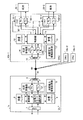
- FIG. 1 is a configuration diagram showing a configuration of a communication system in an embodiment of the present invention.
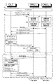
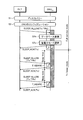
- FIG. 2 is a sequence diagram showing a communication method according to Embodiment 1 of the present invention.
- FIG. 3 is a sequence diagram showing configuration control and sleep control according to Embodiment 1 of the present invention.
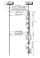
- FIG. 4 is a sequence diagram showing a communication method in the power saving mode according to Embodiment 1 of the present invention.
- FIG. 5 is a diagram showing the relationship between the allowable delay time of downlink data and the average power consumption of ONUs in Embodiment 1 of the present invention.
- FIG. 6 is a diagram showing the relationship between the intermittent operation in the power saving mode and the average power consumption of the ONU in Embodiment 1 of the present invention.
- FIG. 1 is a configuration diagram showing a configuration of a communication system in an embodiment of the present invention.
- FIG. 2 is a sequence diagram showing a communication method according to Embodiment 1 of the present invention.
- FIG. 3
- FIG. 7 is a sequence diagram showing a power saving protocol according to Embodiment 1 of the present invention.
- FIG. 8 is a sequence diagram showing another example of the power saving protocol according to Embodiment 1 of the present invention.
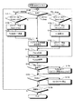
- FIG. 9 is a flowchart showing configuration processing of the control device according to Embodiment 2 of the present invention.
- FIG. 10 is a flowchart showing power saving mode control and the like of the control device according to Embodiment 2 of the present invention.
- FIG. 11 is a flowchart showing a request for the power saving mode of the control device according to the second embodiment of the present invention.
- FIG. 12 is a table showing ONU and service data according to the second embodiment of the present invention.
- FIG. 13 is a table showing service and prohibited power saving mode data according to the second embodiment of the present invention.
- FIG. 14 is a table showing service and prohibited power saving mode data according to the second embodiment of the present invention.
- FIG. 15 is a table showing service and sleep period data according to the second embodiment of the present invention.
- FIG. 16 is a table showing service and maximum sleep period data according to the second embodiment of the present invention.
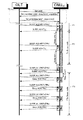
- FIG. 17 is a sequence diagram showing a power saving protocol in the third embodiment of the present invention.
- FIG. 18 is a sequence diagram showing a power saving protocol in the third embodiment of the present invention.
- FIG. 19 is a sequence diagram showing a power saving protocol in the third embodiment of the present invention.
- FIG. 20 is a flowchart showing power saving mode control and the like in the transmission processing of the control device according to Embodiment 3 of the present invention.
- FIG. 21 is a flowchart showing power saving mode control and the like in the reception processing of the control device according to Embodiment 3 of the present invention.
- FIG. 22 is a diagram showing a communication sequence in the fourth embodiment of the present invention.
- FIG. 23 is a diagram showing another example of the communication sequence in the fourth embodiment of the present invention.
- FIG. 24 is a sequence diagram showing insertion of sleep parameters in the fourth embodiment of the present invention.
- FIG. 25 is a flowchart showing processing for selecting an ONU suspension period according to the fourth embodiment of the present invention.
- FIG. 26 is a diagram illustrating a configuration example of a PON system according to Embodiment 5 of the present invention.
- FIG. 27 is a diagram illustrating an example of power consumption for each power saving mode.
- FIG. 28 is a sequence diagram illustrating an example of a power saving mode setting procedure according to the fifth embodiment of the present invention.
- FIG. 29 is a diagram showing another configuration example of the PON system in the fifth embodiment of the present invention.
- FIG. 30 is a sequence diagram illustrating another example of the power saving mode setting procedure according to the fifth embodiment of the present invention.
- Embodiment 1 FIG. ⁇ Hardware configuration
- FIG. 1 is a diagram showing a configuration example of Embodiment 1 of a PON system according to the present invention.
- the PON system of the present embodiment includes an OLT 1 (master station device) and ONUs 10-1 to 10-3 (slave station devices).
- the OLT 1 and the ONUs 10-1 to 10-3 are connected by an optical fiber 30 via a splitter 40.
- the splitter 40 branches the trunk optical fiber 30 connected to the OLT 1 into the number of ONUs 10-1 to 10-3.
- the ONU 10-1 is connected to the terminals 20-1 and 20-2. Although an example in which three ONUs are used is shown here, the number of ONUs is not limited to this, and any number may be used.
- the OLT 1 includes a control unit 2 (OLT control unit) that performs processing on the OLT side based on the PON protocol, a reception buffer 3 that is a buffer for storing uplink data received from the ONUs 10-1 to 10-3, Transmission buffer 4 that is a buffer for storing downlink data to be transmitted to the ONUs 10-1 to 10-3, an optical transceiver 5 that performs transmission / reception processing of optical signals, and WDM (Wavelength) that wavelength-multiplexes uplink data and downlink data
- WDM Wavelength
- a Division Multiplexing (WDM) 6 and a physical layer processing unit (PHY) 7 for realizing a physical interface function of NNI (Network Node Interface) between a network (not shown) are provided.
- NNI Network Node Interface
- the optical transceiver 5 receives the optical signals transmitted from the ONUs 10-1 to 10-3 and converts them to upstream data (Rx: Receiver) 51, and transmits to the ONUs 10-1 to 10-3 An optical transmitter (Tx: Transmitter) 52 that performs transmission processing of downlink data to be converted and transmits the optical signal.
- Rx Receiver
- Tx Transmitter
- the PON protocol is a control protocol used in a MAC (Media Access Control) layer, which is a sub-layer of Layer 2, and is, for example, MPCP (Multi-point Control Protocol) or OAM defined by IEEE (Operation Administration and Maintenance).
- MPCP Multi-point Control Protocol
- OAM defined by IEEE (Operation Administration and Maintenance).
- the ONU 10-1 includes a control unit 11 (ONU control unit) that performs processing on the ONU side based on the PON protocol, and a transmission buffer (upstream buffer) that is a buffer for storing transmission data (upstream data) to the OLT 1 12, a reception buffer (downstream buffer) 13 that is a buffer for storing reception data (downlink data) from OLT1, an optical transceiver 14, a WDM 15 that multiplexes optical signals of upstream data and downstream data, Physical layer processing units (PHYs) 16-1 and 16-2 that implement physical interface functions of UNI (User Network Interface) between the terminals 20-1 and 20-2, respectively.
- PHYs Physical layer processing units
- the optical transmitter / receiver 14 of the ONU 10-1 performs an upstream data transmission process to be transmitted to the OLT 1, converts it into an optical signal, and transmits the optical signal (Tx: Transmitter) 141, and receives the optical signal transmitted from the OLT 1.
- An optical receiver (Rx: Receiver) 142 that performs processing and converts it into downlink data.
- the control unit 11 is connected to the optical transmitter / receiver 14 through a power saving control signal line in order to control the optical transmitter 141 and / or the optical receiver 142 to an on state / off state.
- the PHY 16-1 includes a reception unit (Rx: Receiver) 161-1 that performs reception processing of data transmitted from the terminal 20-1, and a transmission unit (Tx: Transmitter) that performs transmission processing of data transmitted to the terminal 20-1.
- PHY 16-2 similarly, a reception unit (Rx: Receiver) 161-2 that performs reception processing, and a transmission unit (Tx: Transmitter) 162-2 that performs transmission processing, Have
- the communication system of this embodiment includes (1) ONU 10 that can only put the optical transmitter 141 in the power saving state, (2) ONU 10 that can put the optical transmitter 141 and the optical receiver 142 in the power saving state, and (3) There are ONUs 10 that cannot handle power saving control. These ONUs 10 can be classified into four types that correspond to one of the following two power saving modes, both, and none.
- Tx sleep mode Tx_only Sleep mode or Doze mode: The reception function [Rx] is always on, and only the transmission function (Tx) is periodically turned on and off.
- TRx sleep mode TRx Sleep mode or Cyclic sleep mode
- the transmission function [Tx] and the reception function [Rx] are periodically turned on and off.
- the number of terminals is not limited to this, and any number of terminals may be provided, and a physical layer processing unit (PHY) corresponding to the number of terminals is provided.
- PHY physical layer processing unit
- FIG. 1 a configuration example of the ONU 10-1 is shown as a representative, but the ONUs 10-2 and 10-3 have the same configuration as the ONU 10-1.
- the control unit 2 of the OLT 1 performs bandwidth allocation to the ONUs 10-1 to 10-3 so that the uplink data transmission time zones do not overlap, and each ONU 10-1 to 10-3 Is notified as a transmission permission to prevent collision of uplink data transmitted from the ONUs 10-1 to 10-3.
- Any method can be used for this bandwidth allocation, for example, “Su-il Choi and Jae-doo Huh”, “Dynamic Bandwidth Allocation Algorithm for Multimedia Services over Ethernet (registered trademark) PONs”, ETRI Journal, Dynamic Bandwidth Allocation Algorithm described in “Volume 24, Number 6, December 2002, p.465-p.466” can be used.
- the control unit 2 stores the downlink data (downlink communication data) received from the network via the PHY 7 in the transmission buffer 4.
- the control unit 2 reads the downlink data stored in the transmission buffer 4 and outputs it to the optical transceiver 5, and the Tx 52 of the optical transceiver 5 uses the transmission data as an optical signal as WDM 6.
- the WDM 6 performs wavelength multiplexing on the optical signal output from the optical transceiver 5 and outputs it as a downstream signal to the ONUs 10-1 to 10-3 via the optical fiber 30.
- control unit 2 generates a control message for notifying the result of transmission bandwidth allocation as transmission permission, a control message for inquiring link maintenance, and the like, and outputs these control messages to the optical transceiver 5, Transmit to ONUs 10-1 to 10-3 in the same way as data.
- WDMs 6 and 15 are used to perform wavelength multiplexing by using upstream signals and downstream signals as optical signals of different wavelengths. However, when communicating at a single wavelength, WDMs 6 and 15 are used. Instead, the control unit 2 also performs uplink / downlink transmission band allocation.
- upstream data and upstream control messages converted to optical signals are collectively referred to as upstream signals
- downstream data and downstream control messages converted to optical signals are collectively referred to as downstream signals.
- the WDM 15 when receiving the downlink signal from the OLT 1, the WDM 15 separates the downlink signal from the uplink signal and outputs it to the optical transceiver 14, and the Rx 142 of the optical transceiver 14 transmits the downlink signal to the downstream of the electrical signal.
- the data or control message is converted and output to the control unit 11.
- the control unit 11 stores the downlink data output from the Rx 142 of the optical transceiver 14 in the reception buffer 13, and acquires information related to transmission permission and a link maintenance inquiry from the control message. And based on these acquired information, the transmission process mentioned later is performed.
- the control unit 11 also reads the downlink data stored in the reception buffer 13 and outputs it to both or one of the PHYs 16-1 and 16-2 according to the destination of the data.
- the PHYs 16-1 and 16-2 that have received the downlink data perform predetermined processing on the downlink data and transmit the downlink data to the terminals 20-1 and 20-2 to which they are connected.
- the control unit 11 transmits the uplink data acquired from the terminals 20-1 and 20-2 via the PHYs 16-1 and 16-2.
- the uplink data stored in the transmission buffer 12 is read out based on the band allocation result given as transmission permission from the OLT 1 and output to the optical transceiver 14.
- the control unit 11 generates a control message related to the link maintenance and the like and outputs the control message to the optical transceiver 14 based on the transmission band given from the OLT 1.
- the Tx 141 of the optical transceiver 14 converts the upstream data into an optical signal (upstream signal) and transmits it to the OLT 1 via the WDM 15 and the optical fiber 30.
- the OLT 1 converts the optical signal received from the ONUs 10-1 to 10-3 via the optical fiber 30 and the WDM 6 into uplink data and a control message by the Rx 51 of the optical transceiver 5.
- the control unit 2 stores the converted uplink data in the reception buffer 3, performs an operation based on the control message, generates a response to the control message, and discards the control message. Also, when receiving the uplink data, the control unit 2 reads the uplink data once stored in the reception buffer 3 and outputs it to the network via the PHY 7.
- FIG. 2 shows a control sequence in which the OLT 1 operates the ONU 10 in the power saving state in accordance with the capability (power saving function) of the ONU 10.
- step S1 the OLT 1 performs a discovery process in order to find an active ONU 10.
- the OLT 1 broadcasts a discovery control message as a downlink signal, and each ONU 10 that has received this control message returns unique identification information such as the serial number of the ONU to the OLT 1.
- the OLT 1 detects the ONU 10 in the active state by receiving this response control message. can do.
- ONU (2) is turned off and does not return a response message.
- the OLT 1 exchanges various parameters related to the capabilities and communication conditions of the ONU 10 and the ONU 10 detected in step S1, and sets the communication conditions for each other (step S2).
- the OLT 1 shifts to a normal communication state.
- the OLT 1 allocates a bandwidth for uplink communication to each ONU 10 and transmits this to the ONU 10 as transmission permission information (Grant or Gate).
- the OLT 1 may store this Grant together with other data in the downlink direction in a frame and transmit it to the ONU 10 or may transmit it separately.
- a frame can also be called a packet.
- the ONU 10 that has received the grant starts data transmission in the full service mode (both Tx and Rx are on) if there is upstream transmission data in the transmission buffer 12, but here there is no transmission data and the ONU 10 enters the power saving mode.
- a case of shifting will be described (step S3).
- the ONU 10 transmits a request signal requesting permission to transition to the power saving mode to the OLT 1.
- the OLT 1 determines whether or not to permit the transition to the power saving mode based on various information of the ONU 10 obtained in step S2 and the upstream / downstream communication status with the ONU 10 and sends a permission signal (non-permission signal). Send to ONU10.
- the ONU 10 Upon receiving the permission signal, the ONU 10 turns off the power of the optical transmitter 141 (or the optical transmitter 141 and the optical receiver 142) for a predetermined period based on the permission signal, and reduces the power consumed by the optical transmitter / receiver 14. To reduce. Note that the OLT 1 can permit a power saving mode different from the power saving mode requested by the ONU 10 according to the configuration result.
- step S3 the OLT 1 allocates a bandwidth to the ONU 10 in the Tx sleep mode in which the power of the optical transmitter 141 is turned off, and transmits a grant.
- the ONU 10 that has received the grant generates a control message requesting cancellation of the Tx sleep mode when uplink data to be transmitted is generated, turns on the power of the optical transmitter 141, and transmits data to the OLT 1 using the allocated bandwidth. Is generated, or a control message for requesting cancellation of the Tx sleep mode is generated and transmitted to the OLT 1 using a band allocated by Grant.
- the ONU 10 monitors the occurrence of uplink data exceeding a predetermined threshold and the start of communication of a terminal (connected device) that requires a large bandwidth, and decides to cancel the power saving mode based on the monitoring result. .
- the ONU 10 that has decided to release the power saving mode can notify the OLT 1 of the decision to release the power saving mode by transmitting a release message SLEEP_ACK (wake up) or data to the OLT 1 using the received Grant.
- the OLT 1 that has received the release message or data from the ONU 10 determines that the ONU 10 has exited the power saving mode and has shifted to the full service mode (both Tx and Rx are in the on state). Assign Grant.
- the OLT 1 may determine that the power saving mode release decision of the ONU 10 has been made.
- step S4 When ONU (2) is discovered by discovery (step S4) periodically performed by OLT1, configuration is performed between OLT1 and ONU (2) (step S5).
- the configuration with the ONU (1) in step S5 is performed. Can be omitted. If the configuration is performed in step S5 and the result is different from the result in step S2, the configuration result performed later (in this case, the result in step S5) is prioritized.
- ONU (2) When the configuration is completed, ONU (2) starts communication.
- the ONU (2) that has received the Grant from the OLT 1 transmits a request (SLEEP_REQ) requesting permission to transition to the power saving mode in the same manner as in Step S3 when there is no uplink data (Step S7).
- step S7 the ONU (1) and ONU (2) transmit a request (SLEEP_REQ) for transition to the power saving mode to the OLT 1.
- the OLT 1 starts communication with the ONU (1) by the power saving protocol in the Tx sleep mode based on the configuration result.
- OLT 1 confirms the state of the downlink buffer (transmission buffer 4) and decides the power saving mode to be permitted. Communication with the ONU (2) is started using a power saving protocol corresponding to the power mode.
- Step S7 will be described in detail with reference to FIG.
- the power saving mode is selected based on the result of detecting the requested power saving mode, the communication status, and the information on the power saving mode permitted in the configuration ( Step S7a). Then, the selected result is returned to the ONU 10 as a permission notice (or a non-permission notice). The details of the selection of the power saving mode and the transition to the power saving mode will be described later.
- the ONU 10 can also specify information of the power saving mode to be shifted together with the request (SLEEP_REQ) at step S6.
- the OLT 1 starts communication with the ONU (2) using a power saving protocol corresponding to the designated information.
- the power saving mode that the ONU 10 wishes to transition to is designated, for example, it can be considered that the ONU 10 can shift to the power saving mode after communication is started. This situation occurs when only intermittent and small data communication or small-band voice communication occurs due to web browsing, or when only the IP phone is turned on and in standby mode. appear.
- These conditions are detected by the ONU 10 by monitoring the transmission buffer 12 and the status of the connected device, and when the predetermined conditions are satisfied, the transition to the power saving mode is determined and the transition to be made is determined. Notify OLT 1 as the power mode. For example, the judgment of ONU 10 transition is made by using a comparison table of the power saving mode that can be transitioned with the state of the connected device when the total traffic amount or average value of the upstream and downstream traffic for a predetermined period falls below a threshold value, or the like. This is performed when the predetermined condition matches (steps S6a and S6b).
- the ONU 10 checks whether the power saving mode determined from the traffic state corresponds to the power saving mode permitted from the OLT 1 by accessing a storage device (not shown) (step S6c).
- a request (SLEEP_REQ) is transmitted to OLT1.
- the ONU 10 changes the mode to one corresponding to the permission mode and transmits a request or suppresses transmission of the request. In this way, by suppressing requests that do not fall into the permission mode, it is possible to save wasteful bandwidth consumption and processing power.
- step S6 is not essential.
- the OLT 1 periodically transmits a control message for inquiry about link maintenance to the ONU 10 discovered in step S1.
- the ONU 10 that has received the inquiry message returns a response message.
- the OLT 1 receives the response message, the ONU 10 maintains the link state, and when the response is not received continuously for a predetermined number of times, the link is disconnected.
- the ONU 10 in the power saving mode periodically turns on the power of the optical transmitter 141 (or the optical transmitter 141 and the optical receiver 142) in order to respond to this link maintenance inquiry.
- the ONU 10 can also transmit other control information and a small amount of data stored in the transmission buffer 12 by using the bandwidth allocated for the link maintenance response.
- a dedicated control message can be used for the inquiry about link maintenance, but in this PON system, Grant that notifies bandwidth allocation is used as a control message for inquiry about link maintenance.
- the OLT 1 transmits a Grant for each band update period regardless of the operation mode.
- the ONU 10 returns Data every time in the full service mode (timing u1, u2), but does not respond when the optical transmitter 141 is turned off after transmitting a sleep request in the Tx sleep mode (timing u3). (Timing u4, u5), a response is made when the optical transmitter 141 is temporarily turned on (timing u6). That is, the grant received by the ONU 10 at timings u4 and u5 is merely a bandwidth allocation notification for uplink data transmission of the ONU 10, and no link maintenance inquiry is made. The grant received at timing u6 is allocated for bandwidth allocation for uplink data transmission. This indicates that inquiries regarding link maintenance are made in addition to notifications.
- Whether the inquiry cycle for maintaining the link and the Grant transmission cycle are the same is determined between the OLT 1 and the ONU 10 by a power saving protocol or the like. If uplink data to be transmitted to the ONU 10 is generated during a period in which the power of the optical transmitter 141 is off, if there is a bandwidth allocation, the ONU 10 turns on the power of the optical transmitter 141 and transmits data to the OLT 1 be able to. Alternatively, a control message requesting cancellation of the Tx sleep mode can be generated, and this control message can be transmitted to the OLT 1 using the allocated bandwidth. With such a power saving protocol in the Tx sleep mode, the ONU 10 can transmit data with a short delay time even when uplink data occurs.
- the OLT 1 may perform bandwidth allocation for each ONU 10 in which the power of the optical transmitter 141 is turned off for each bandwidth update period in the full service mode, or in the full service mode considering that there are few uplink communications. It may be performed once every several times.
- the ONU 10 in the Tx sleep mode must turn on the power of the optical transmitter 141 to respond to the link maintenance inquiry from the OLT 1, and if it responds to every Grant, power consumption is wasted. Therefore, in the power saving protocol of the Tx sleep mode, the inquiry about the link maintenance from the OLT 1 is set to once every several times of the bandwidth allocation notification, and the number of responses of the ONU 10 to the Grant is suppressed, and the optical transmitter 141 is turned off. Lengthen. By doing so, the link state can be maintained while reducing power consumption.
- the power saving protocol of TRx sleep mode makes the inquiry period for link maintenance and the bandwidth allocation period the same, and the period during which the power of the optical transmitter 141 and the optical receiver 142 is turned off is transmitted in the full service mode. It is set longer than the period and shorter than the power-off period of the optical transmitter 141 in the Tx sleep mode.
- TRx sleep mode the power supply of optical transmitter 141 and optical receiver 142 is turned on / off together, so there is no need to change the cycle between link maintenance inquiry and bandwidth allocation, and the uplink communication is higher than in full service mode. This is because the grant transmission interval can be lengthened because there are few.
- the ONU 10 in TRx sleep mode turns off the power of the optical receiver 142 in addition to the optical transmitter 141, the power consumption can be reduced.
- the Grant transmission interval as described above, the link state is set in the power saving mode. Thus, data can be transmitted with a short delay time when upstream data occurs in the ONU 10.
- step S5 both ONU (1) and ONU (2) perform configuration with OLT1.
- the same reference numerals as those in FIG. 2 denote the same or corresponding processes.
- This protocol is an example, and the present invention is not limited to the various transmission frames shown in FIG. 3 and their names and procedures.
- the extended OAM eOAM
- OMCI ONU management and control interface
- ONT management and control interface ONT management and control interface
- the ONU 10 determines the connected device type such as the terminal 20-1, on / off, line type, speed, and the idle period during which the power saving operation is performed (related to the T_SLEEP period in FIG. Time), information on attributes such as a temporary start-up time (time related to the period of T_AWARE in FIG. 4) in which the optical transceiver 14 is turned on intermittently in the power saving mode is collected (step S5a).
- the attribute information is generated together with the information about the function and performance of the own device recorded in the storage device (not shown) of the own device (step S5b).
- the ONU 10 records correspondence information (power_save_attr) of the power saving function as the attribute information.
- the OLT 1 transmits a request command (Get_cmd) for attribute information of the ONU 10.
- Each ONU 10 returns attribute information in response frame (Get_rsp) in response to this request command.
- the ONU 10 that does not support the power saving function may not transmit the power saving function correspondence information (power_save_attr).
- the OLT 1 When the OLT 1 receives the response frame (Get_rsp), it records the attribute information of the ONU 10 acquired in its own storage device (database) in the format shown in FIG.
- the storage device of the OLT1 includes a suspension period T1 for Tx sleep mode (a power saving period in which the ONU 10 in the Tx sleep mode turns off the transmitter 142) and a suspension period T2 for the TRx sleep mode (TRx sleep mode).
- the power saving period during which the ONU 10 of the optical transmitter 141 and the optical receiver 142 are turned off) is recorded in advance. Similarly, contract information for each user is also recorded.
- the OLT 1 checks the power-saving mode restrictions for each user and service provided (step S5c), and determines the power-saving mode and conditions permitted to each ONU 10 ( Step S5d). Examples of restrictions are shown in FIGS. For example, when the user uses a communication line for a server application that requires a quick response, it is not desirable that the ONU 10 shifts to the power saving mode and a delay occurs. The OLT 1 and the ONU 10 can suppress such an undesirable delay in advance by confirming in advance a power saving mode permitted before starting communication.
- FIG. 5 shows the relationship between the allowable delay time of downlink data and the average power consumption of ONU10.
- the solid line indicates the Tx sleep mode whose pause period is the same as that of the TRx sleep mode
- the alternate long and short dash line indicates the Tx sleep mode according to the present embodiment (the pause period is different from the TRx sleep mode)
- the broken line indicates the TRx sleep mode.
- the average power consumption of the ONU 10 is normalized based on the power consumption in the full service mode.
- FIG. 6 shows a relative relationship between the power consumption during the period in which the power is intermittently turned on in the Tx sleep mode and the TRx sleep mode (T_AWARE) and the period in which the power is turned off (T_SLEEP).
- the longer the allowable delay time of downlink data the lower the power consumption. That is, if the pause period in the power saving mode is set to be long, the power consumption of the ONU 10 can be reduced. However, if the pause period is set longer in the TRx sleep mode, the delay time when upstream data is generated in the ONU 10 is also increased accordingly. On the other hand, in the Tx sleep mode, even if the pause period is set longer, the ONU 10 can cancel the power saving mode as described above, so that data can be transmitted with a short delay time.
- the Tx sleep mode pause period and the TRx sleep mode pause period are individually set, and the Tx sleep mode pause period is set to be equal to or greater than the TRx sleep mode pause period. Since the ONU 10 in the Tx sleep mode can receive downlink data even during the suspension period, the power saving state (power off state of the optical transmitter 142) is maintained even when the allowable delay time of downlink data is as short as several ms. Can keep. Thereby, power consumption can be reduced as compared with the conventional Tx sleep mode using the same pause period as the TRx sleep mode.
- Tx sleep mode is set to 500 ms, which can reduce power consumption, and TRx sleep mode is set to 50 ms based on the call response request time of a telephone (a typical service that requires low delay). It is possible to do.
- the set value is not limited to this.
- the OLT 1 generates an instruction frame (Set_cmd) including information on the determined permitted power saving mode and the corresponding suspension period in the ONU 10 and transmits it to the ONU 10.
- the ONU 10 receives the instruction frame (Set_cmd)
- the ONU 10 records the permitted power saving mode and suspension period in its own storage device (step S5e).
- the OLT 1 can insert information on the two permitted power saving modes and suspension periods T1 and T2 into the instruction frame (Set_cmd) transmitted to the ONU 10.
- the instruction frame can include the respective information.
- the OLT 1 notifies different suspension periods T1 and T2 depending on the power saving mode of the ONU 10, thereby reducing the power consumption of the ONU 10 in the Tx sleep mode and the ONU 10 in the TRx sleep mode with uplink data with a short delay time. Can be sent.
- step S5d and step S5e When there are a plurality of power saving modes permitted in step S5d and step S5e, it is necessary to determine which power saving mode the OLT 1 or ONU 10 selects before the ONU 10 transitions to the power saving mode.
- the description will be divided into four cases.
- the OLT 1 generates a control message SLEEP_ALLOW (Tx
- the ONU 10 that has received SLEEP_ALLOW selects one of the power saving modes based on its own capability (having the power saving function), and corresponds to the selected power saving mode during the suspension periods T1 and T2 previously notified from the OLT 1 What is to be stored is stored as a pause period of the own device. For example, when the ONU 10 selects the Tx sleep mode, the ONU 10 generates SLEEP_ACK (Tx) including information on the selected power saving mode as a response to the SLEEP_ALLOW and returns it to the OLT 1.
- the ONU 10 transitions to the Tx sleep mode.
- the OLT 1 receives SLEEP_ACK (Tx)
- it records that the power saving mode of the ONU 10 is the Tx sleep mode in the storage unit within itself and recognizes that the ONU 10 has transitioned to the Tx sleep mode.
- ONU 10 corresponds to Tx sleep mode
- ONU 10 that has received SLEEP_ALLOW (Tx
- TRx the state of the upstream buffer
- the OLT 1 decides the power saving mode to be permitted in its own device, and transmits the determined power saving mode (Tx or TRx) as a permission notice (SLEEP_ALLOW) to the ONU 10 exactly.
- a response from the ONU 10 to the OLT 1 is not essential.
- the OLT 1 registers that the ONU 10 transitions to the power saving mode at the time when the permission notification reaches the ONU 10 in consideration of the RTT (Round Trip Time), the setup time of the optical transceiver 14, and the ONU 10 When received, the mode transits to the power saving mode.
- the ONU 10 responds to the OLT 1
- the ONU 10 shifts to the power saving mode when responding to the permission notification, and the OLT recognizes that the ONU 10 has transitioned to the power saving mode when receiving this response. If there is no response from the ONU 10 within a predetermined time, if the OLT 1 retransmits the permission information, the power saving mode can be reliably recognized between the OLT 1 and the ONU 10.
- ONU 10 transmits to OLT 1 a control message SLEEP_REQ requesting a query to shift to the power saving mode.
- the OLT 1 that has received SLEEP_REQ transmits SLEEP_ALLOW (Tx
- the ONU 10 determines its own power saving mode based on the state of the transmission buffer 12, and transmits SLEEP_REQ including information on the determined power saving mode to the OLT 1.
- the OLT 1 that has received this SLEEP_REQ determines whether or not the power saving mode determined by the ONU 10 can be permitted based on the information on the power saving mode determined by the ONU 10 and the information recorded in the storage device, and the permission notification SLEEP_ALLOW (or Non-permission notification) is transmitted to the ONU 10.
- the ONU 10 receives the SLEEP_REQ permission notification
- the ONU 10 transitions to the power saving mode, and the OLT 10 recognizes that the transition to the power saving mode occurs when the permission notification reaches the ONU 10.
- the ONU 10 since the ONU 10 selects and determines the power saving mode in advance, the inquiry from the OLT 1 to the ONU 10 can be omitted, and the procedure can be simplified. Further, since the OLT 1 is assigned a band to the ONU 10 regardless of the power saving mode of the ONU 10, the ONU 10 can transmit the upstream traffic with a small delay time.
- the ONU 10 When the permitted power saving mode is one, when the ONU 10 shifts to the power saving mode, an inquiry is made from the OLT 1 as in (a) and (b) above, or (c) and (d) above. By making a request from the ONU as described above, it is possible to recognize the state of the operation mode between the OLT 1 and the ONU 10.
- the ONU 10 generally transmits SLEEP_REQ when the ONU 10 shifts to the power saving mode when SLEEP_ALLOW (Tx
- FIG. 7 shows a state where the ONU 10 shifts from the Tx sleep mode to the TRx sleep mode and then shifts to the Tx sleep mode again.
- the mode change between the plurality of power saving modes may be spontaneously executed by the ONU 10 based on the determination of the ONU 10 described in steps S6a to S6c in FIG. 2, but the OLT 1 instructs the mode change. Is also possible.
- the OLT 1 instructs the mode transition will be described as an example.
- ONU10 operating in full service mode during period P1 specifies Tx sleep mode and sends a transition request (SLEEP_REQ) to power saving mode to OLT1, OLT1 decides whether or not to allow power saving.
- Step S7a a request permission response (SLEEP_ALLOW (Tx)) is returned.
- the ONU 10 shifts to the Tx sleep mode when receiving this permission notice, and operates in the Tx sleep mode during the period P2.
- SLEEP_ACK (Tx) is returned to OLT1.
- the ONU 10 that has shifted to the Tx sleep mode cuts the supply power of the optical transmitter 141 while maintaining the supply power of the optical receiver 142, and starts operation with reduced power consumption.
- Tx and Rx indicate the power-on state of the optical transmitter 141 and the optical receiver 142, respectively (the power-off state is in a period not described).
- the OLT 1 can transmit downlink data.
- “transmittable” means that the ONU 10 can receive the data transmitted by the OLT 1.
- OLT 1 gives Grant to ONU 10 together with downlink data. The ONU 10 receives the Grant, but when there is no transmission data, it does not supply power to the optical transmitter 141 and suppresses power consumption.
- the OLT 1 detects this from the monitoring result of the transmission buffer 4 and the like, examines the result of the configuration in step S2 stored in the storage device, and performs downlink communication. Determine whether to enter power saving mode.
- the detection of the end of the downlink traffic is performed, for example, based on whether or not the downlink traffic read from the transmission buffer 4 during a certain period has become a predetermined threshold value or less.
- the OLT 1 When it is determined that the OLT 1 changes from the Tx sleep mode to the TRx sleep mode, the OLT 1 designates the mode (TRx) to be changed by the sleep mode change request (SLEEP_ALLOW) and transmits it to the ONU 10.
- the ONU 10 that has received this change instruction transmits SLEEP_ACK (TRx) in the same manner as the transition to the power saving mode in step S7, and switches the power saving mode from the Tx sleep mode to the TRx sleep mode.
- the ONU 10 operates in a state where the power supplied to the optical receiver 142 is cut and the power consumption is further suppressed.
- TRx sleep mode cyclic sleep is performed in which the power is turned off and on at regular or variable intervals.
- the period of time during which the power is turned off is specified by a parameter called sleep time.
- the sleep time may be a default value determined by configuration (the sleep period T1 in the case of Tx sleep mode, the sleep period T2 in the TRx sleep mode), or a value specified by SLEEP_ALLOW (TRx). For example, when the sleep time is not designated by SLEEP_ALLOW (TRx), the ONU 10 and the OLT 1 use the default sleep period T2.
- the sleep time can be specified by, for example, a method for specifying a power-off period of the optical transceiver 14, a method for specifying a start time and an end time, and a method for specifying a power-off start time and a power-off duration. . In the following description, it is assumed that sleep time is specified only during the power-off period.
- the ONU 10 temporarily turns on the power of the optical transmitter 141 and the optical receiver 142 according to the sleep time, and whether to continue the TRx sleep mode in response to the inquiry from the OLT 1 or the power saving mode It responds (SLEEP_ACK) whether or not to request the change.
- the OLT 1 can confirm that no line failure has occurred with the ONU 10 by receiving SLEEP_ACK.
- the OLT 1 determines whether or not to change the sleep mode (step S11), and if so, a change request (SLEEP_ALLOW). Is transmitted to ONU10. At this time, if it is determined that the traffic increases only in the downstream communication, the OLT 1 may instruct the ONU 10 by transmitting SLEEP_ALLOW (Tx) so as to change from the TRx sleep mode to the Tx sleep mode.
- This instruction has an effect that the power consumed by the ONU 10 can be reduced as compared with the case where the TRx sleep mode is shifted to the full service mode (both Tx and Rx are in the on state).
- the OLT 1 When canceling the power saving mode of the ONU 10 operating in the Tx mode, the OLT 1 transmits a change request (SLEEP_ALLOW (AWAKE)) to the ONU 10.
- the ONU 10 that has received SLEEP_ALLOW (AWAKE) from the OLT 1 turns on the power of the optical transmitter 141 to shift to the full service mode, and transmits SLEEP_ACK (AWAKE) as a response to the OLT 1.
- two messages SLEEP_ALLOW and SLEEP_ACK are used to change the mode between the Tx sleep mode and the TRx sleep mode.
- Mode switching may be performed.
- the ONU 10 operating in the power saving mode can detect this from the amount of data stored in the transmission buffer 12 monitored when upstream traffic occurs in order to shift to the full service mode. Then, the optical transmitter 141 is turned on to shift to the full service mode. Thereafter, the ONU 10 transmits SLEEP_REQ (WAKE_UP). When the OLT 1 receives this, the ONU 10 recognizes that it has shifted to the full service mode, and resumes the grant transmission in the full service mode.
- the time for turning off the power of the optical transceiver 14 of the ONU 10 according to the power saving mode can be set individually for the Tx sleep mode and the TRx sleep mode. If the idle period of the ONU 10 is longer than the idle period of the ONx 10 in the TRx sleep mode, the power consumption of the ONU 10 in the Tx sleep mode is reduced from the power consumption of the conventional Tx sleep mode even if the allowable delay time of downlink data is short it can. In addition, the suspension period corresponding to the power saving mode can be changed by newly negotiating between the OLT 1 and the ONU 10 as necessary.
- Embodiment 1 the PON system that sets different suspension periods according to the power saving mode has been described.
- the OLT 1 forcibly changes the power saving mode if the allowable delay time of downlink data is less than a predetermined threshold when the power saving mode is selected or changed.
- FIG. 9 is a flowchart for explaining the processing of the control unit 2 in the OLT 1 of the second embodiment.
- the control unit 2 according to the second embodiment is applicable to the communication system according to the first embodiment, and is similar to the first embodiment in terms of the entire communication system.
- the control unit 2 is a control device used for a base unit such as the OLT 1 and is configured by a combination of a digital signal processor, a general-purpose processor and software. These processors are made into chips by highly integrated ICs (Integrated Circuits), and function as OLT 1 by being combined with optical transmitter / receiver 5 and the like through signal lines.
- the control unit 2 starts discovery via the optical transceiver 5. Since the serial number of the ONU 10 is obtained in the discovery, the control unit 2 accesses a built-in or externally connected storage device based on this, and specifies a user who uses the ONU 10. Then, the control unit 2 associates the user and the service contracted by the user (step S50). For example, FIG. 12 shows an example of the correspondence, and the control unit 2 determines whether the ONU serial number, the user ID, and whether the user has a contract for business use or other general home users. The service information such as the contract is associated. The association information includes information on the type of service line (IPTV, IP phone, other Internet) and the like. These service lines have different service request conditions (QoS) such as guaranteed bandwidth and allowable delay time for each uplink and downlink depending on the type.
- QoS service request conditions
- the control unit 2 starts configuration of the ONU 10 corresponding to step S2 in FIG.
- the control unit 2 generates a request message (Get_cmd) and sends it to each ONU 10 in order to request the power saving function correspondence information (power_save_attr) from each ONU 10 (step S51).
- the control unit 2 can also request attribute information of other ONUs 10.
- the attribute information of the ONU 10 is information specified in, for example, ITU-T G.984.4 ONT management and control interface, and the configuration method can be implemented in the same manner. It may also be obtained using information and methods similar to ITU-T G.988 ONU management and control interface and equivalent standards such as the next generation standard XG-PON that will be developed.
- the control unit 2 obtains the correspondence information OCi of the power saving function received from each ONU i by the optical transceiver 5 from the buffer or the optical transceiver 5 (step S52), and the serial of the active ONU 10 identified by the discovery.
- the ONU 10 that does not have the power saving function correspondence information OCi is identified as the ONU 10 that does not support the power saving function (step S53).
- the control unit 2 identifies the ONU 10 as an ONU 10 not compatible with the power saving function.
- the control unit 2 writes the correspondence information in the internal storage device or the like in association with the ONU 10 in the form shown in FIG. 12, for example (step S54).
- the correspondence information acquired by the control unit 2 includes not only the power saving mode but also various parameters related to the power saving function such as a sleep period. Therefore, although not shown in FIG. 12, the control unit 2 similarly records these various parameters in the storage device.
- control unit 2 accesses a service database (storage device) as shown in FIGS. 12 to 16, and determines a power saving mode and a power saving parameter permitted for each of the N ONUi (steps S5c, S5d). ). This determination can be performed, for example, by the following method.
- the control unit 2 reads out the service ID contracted by the user from the storage device (see FIG. 12) based on the user identifier (ID) associated with ONUi, and displays the prohibited power saving mode Fi for each service ID. 13 and the information table shown in FIG. At this time, the power saving mode prohibited for ONUi may be determined by any algorithm, but if it is “impossible” in either of FIG. 13 and FIG. The power saving mode is set to the prohibited power saving mode Fi.
- the control unit 2 identifies a power saving mode that can be supported by the ONUi itself from the information table of FIG. 12, and permits power saving by excluding the prohibited power saving mode Fi from the power saving mode identified here. Determine the mode AMi.
- the power saving mode AMi to be permitted is stored in the storage device.
- the control unit 2 when acquiring the sleep time from the ONU 10, stores it in the storage device as the acquired sleep period GSTi (FIG. 15).
- the sleep time is one of the parameters related to the power saving function, and can be used instead of the default sleep periods T1 and T2 set in advance in OLT1.
- the control unit 2 selects the acquired sleep period GSTi or the default sleep period, and stores it in the storage device as the sleep time applied to the ONU 10.
- the acquired sleep period GSTi is used.
- the control unit 2 can also adjust the sleep time using a regulation value or a default value determined in advance according to the service, as the power saving mode is adjusted based on the service information. For example, if the sleep time notified by the ONU 10 is excessively long, the communication quality of upstream communication will be degraded, or the downstream traffic will compress the storage area of the OLT1 reception buffer, so the adjusted value will be acquired. Store in memory as time GSTi.
- the control unit 2 also stores the maximum sleep period MaxSTi acquired from ONUi in the storage device (see FIG. 16).
- the maximum sleep period MaxSTi is a regulation value when the acquired sleep time GSTi is dynamically adjusted, and may be set in advance in the OLT 1 instead of being acquired from the ONU 10. Further, the control unit 2 may use MaxSTi as a judgment condition for alarms such as LOS (loss of signal) and LOB (loss of burst).
- the OLT 1 may store the tables of FIGS. 15 and 16 respectively in two types, a table stored in advance by the OLT 1 and a table determined as a result of negotiation with the ONU 10.
- the control unit 2 When the permission mode AMi, the sleep time STi, and the maximum sleep period MaxSTi for these power saving modes are determined for each ONU 10, the control unit 2 notifies each ONU 10 of these parameters using a message (Set_cmd) (step S55). . After receiving Set_cmd, the ONU 10 records these parameters in the storage device of the ONU 10 and uses them for controlling the power saving protocol.
- the connector indicated by [A] in FIG. 10 indicates a continuation of the flow indicated by the connector [A] in FIG.
- the control unit 2 performs band allocation control in the power saving mode in steps S60 to S65.
- the OLT 1 detects the upstream / downstream traffic or the state of the connected device of the ONU 10 from the state of the buffers 3 and 4 of the OLT 1 and information transmitted from the ONU 10. This state information is used for bandwidth allocation in step S66 and determination of transition to the power saving mode in step S67.
- the control unit 2 checks the current power saving mode of the target ONU 10, and performs a bandwidth allocation limit and a grant grant limit according to each mode (step S61).
- the control unit 2 does not limit the bandwidth allocation due to the power saving mode.
- the control unit 2 limits the allocated bandwidth limit Bi of uplink communication to a predetermined value or a value determined according to the service (step S62).
- the control unit 2 sets Bi similarly to step S62 (step S63), and the Grant opportunity is m times of the band update cycle (m is an integer of 1 or more). (Step S64).
- the grant skip flag GSi is set as a flag for not allocating a transmission opportunity of the bandwidth update cycle, and when this flag is set in step S66, the control unit 2 sets the transmission opportunity to the ONUi in that cycle. Don't give.
- the control unit 2 sets the flag GSi (m ⁇ 1) times m times, thereby giving the ONU 10 one transmission opportunity in m band transmission cycles.
- the bandwidth allocation method according to the power saving mode described above is an example, and the control unit 2 sets the bandwidth in each mode to be restricted / unrestricted and the transmission opportunity restricted / unrestricted as necessary. Can do.
- the control unit 2 can restrict the grant and uplink data transmission opportunities even in the Tx sleep mode, or grant the grant every time without performing the grant skip for the ONU 10 in the TRx sleep mode. it can.
- the bandwidth limitation is also arbitrary. For example, even if the allocation bandwidth limitation Bi is not set intentionally, there is no uplink traffic from the ONU 10, or the bandwidth allocation request value is small, and the dynamic bandwidth allocation in step S66 is performed. Since the allocated amount is relatively smaller than that of the other ONUs 10, the control unit 2 can perform bandwidth allocation without distinguishing between the ONUs 10 in the power saving mode and the ONUs 10 that are not.
- the control unit 2 allocates a bandwidth to each ONU 10.
- the above-described grant skip flag GSi and allocated bandwidth limitation Bi are used.
- the control unit 2 removes the ONUi in which the grant skip flag GSi is set from the bandwidth allocation target for the next period, and then uses the Traffic monitoring DBA (Dynamic Bandwidth Allocation), status report DBA, or a combination of these to each ONU10. Allocate bandwidth.
- the control unit 2 does not give the bandwidth exceeding the allocated bandwidth limit Bi to the ONUi in the power saving mode.
- the control unit 2 resets each GSi and Bi.
- step S67 the control unit 2 prepares to generate SLEEP_ALLOW, which is a permission signal, based on the request (SLEEP_REQ) received by the optical transceiver 5. Specific processing will be described later with reference to FIG.
- control unit 2 performs power saving mode change instruction control by the OLT 1 in steps S68 to S75.
- the OLT 1 can shift the subordinate ONU 10 from the power saving mode to the full service mode, or from one power saving mode to another power saving mode. The power can be reduced and the communication quality can be improved.
- the control unit 2 examines the storage device to detect whether the ONU i is in the sleep mode (step S69). If the ONU i is not in the sleep mode, the control unit 2 checks whether there is a cause for starting the sleep mode (step S70). If it is determined that there is no start factor, the control unit 2 moves to the process of step S75, and repeats the same process for the next ONUi (ONUi obtained by incrementing the value of i by 1).
- control unit 2 proceeds to the processes of steps S71 and S72, respectively. Then, preparation for transmitting SLEEP_ALLOW is made in order to shift the ONU 10 to the power saving mode.
- the control unit 2 designates the TRx sleep mode as the power saving mode (step S71). If uplink communication continues even if traffic decreases in the downlink, the TRx sleep mode is not selected, and the process proceeds to step S75. On the other hand, when there is downlink traffic but the uplink traffic decreases and the mode shifts to the power saving mode, the control unit 2 designates the Tx sleep mode as the power saving mode (step S72).
- step S73 When it is determined in step S69 that the ONU i is in the sleep mode, the control unit 2 detects a sleep mode interruption factor (step S73). If there is no cause for interruption, the control unit 2 continues the sleep mode and proceeds to processing of the next ONU 10. On the other hand, if the cause of interruption is uplink (upstream traffic exceeding the threshold), prepare to send SLEEP_ALLOW with AWAKE in order to stop the power saving mode and shift to the full service mode. (Step S74). In addition, when the interruption factor is downlink (occurrence of downlink traffic exceeding the threshold), the control unit 2 is configured to shift the ONU 10 from the TRx sleep mode to the Tx sleep mode or to continue the Tx sleep mode. , Preparation for transmitting SLEEP_ALLOW (Tx) is performed (step S72).
- the sleep start factor and interrupt factor may be any standards as long as the required communication quality can be maintained while suppressing power consumption.
- the amount of traffic in a certain period as described above, the amount of data stored in the buffer, the on / off information of the connected device connected to the ONU 10, or the start of a new service is a standard.
- control unit 2 When the above processing is completed, the control unit 2 generates a frame storing a control result message such as a bandwidth allocation result and SLEEP_ALLOW, and transmits the frame to the ONU 10 (step S76). At this time, it is also possible to store the downlink data in the same frame as the control message and transmit it together.
- a control result message such as a bandwidth allocation result and SLEEP_ALLOW
- control unit 2 determines whether it is time to perform discovery (step S77). If necessary, the process proceeds to step S1 in FIG. 9 (see connector [B]), and discovery is necessary. If not, the process returns to step S60 in FIG. 10 and shifts to transmission control in the next band update cycle.
- FIG. 11 shows an example of a preparation process for generating SLEEP_ALLOW based on a request (SLEEP_REQ) received by the control unit 2 of the OLT 1.
- the control unit 2 determines whether to permit or change the request from the ONU 10, and responds with the result as a SLEEP_ALLOW message.
- the control unit 2 checks whether the power saving mode specified as a parameter in SLEEP_REQ is included in the permission mode AMi of the ONUi by accessing the storage device (step S91). If the power saving mode is not designated here, the control unit 2 sets the power saving mode to the default value of the power saving mode determined in advance by the configuration such as step S2 in FIG. 2 (step S92). . On the other hand, if the designated mode is not in the permission mode AMi, the control unit 2 changes this to the permission mode or sets rejection information for shifting to the power saving mode (step S93). Note that when the control unit 2 changes the power saving mode designated by the ONU 10, it is necessary to prevent the communication quality from being hindered.
- the control unit 2 proceeds to the next step S94.
- the control unit 2 determines whether or not the permission mode AMi or the default power saving mode is the TRx sleep mode (step S94).
- the TRx sleep mode it is determined whether or not the allowable delay time Tdd of downlink data is less than a predetermined threshold value Tth (step S95). This allowable delay time Tdd can be specified by the service ID, user ID, etc. of FIG.
- the predetermined threshold value Tth is an allowable delay time at the intersection of the graphs of the Tx sleep mode and the TRx sleep mode in FIG.
- the power consumption of Tx sleep mode is lower than that of TRx sleep mode when the allowable delay time Tdd of downlink data is less than the threshold value Tth, and when the allowable delay time Tdd of downlink data is equal to or greater than the threshold value Tth, Even TRx sleep mode consumes less power.
- step S95 If it is determined in step S95 that the allowable delay time Tdd of the downlink data is less than the threshold value Tth, the control unit 2 determines to forcibly change the permission mode AMi to the Tx sleep mode, and shifts to the power saving mode.
- the refusal information for is set (step S96).
- the OLT 1 forcibly changes the power saving mode, so that the power consumption of the ONU 10 can be reduced.
- the Tx sleep mode is not changed to the TRx sleep mode. This is because it is necessary to confirm whether there is downlink data. Confirmation of the presence / absence of downlink data is performed by the processing corresponding to steps S69 to S75 in FIG.
- step S96 When it is determined in step S96 that the process is not in the TRx sleep mode in step S94, or when it is determined in step S95 that the allowable delay time Tdd is greater than or equal to the threshold value Tth, the control unit 2 sleeps specified as a parameter in SLEEP_REQ. It is checked by accessing the storage device whether time is equal to or shorter than the maximum sleep period MaxSTi set for the ONUi (step S97). If the sleep time is not specified here, the control unit 2 sets the sleep time default value STi determined in advance by the configuration such as step S2 in FIG. 2 to the sleep time (step S98). On the other hand, when the designated sleep time is larger than MaxSTi, the control unit 2 changes this to MaxSTi or sets rejection information for shifting to the power saving mode (step S99).
- the control unit 2 When the above processing is completed or when sleep time ⁇ MaxSTi, the control unit 2 records the power saving mode information PSi as the power saving mode information of the corresponding ONUi in the storage device, and at the same time, step S64 in FIG.
- the sleep time is set in the grant timing of S66 and the timer PSTi which is a reference for alarm suppression during power saving (step S100).
- control unit 2 repeats the above process for all the received SLEEP_REQ (step S101).
- the PON system that sets different suspension periods in the Tx sleep mode and the TRx sleep mode has been described.
- a PON system in which different pause periods are set for the uplink and the downlink will be described.
- FIG. 17 is a sequence diagram showing a communication protocol in the sleep mode in this embodiment.
- the same reference numerals as those in FIG. 7 or FIG. 8 indicate the same sequences.
- the OLT 1 transmits the sleep_time1 for uplink and the sleep_time2 for downlink to the ONU 10.
- sleep_time1 indicates a period during which the power consumption of the optical transmitter 141 is reduced (pause period of the optical transmitter 141)
- sleep_time2 indicates a period during which the power consumption of the optical receiver 142 is reduced (pause period of the optical receiver 142). Show.
- a period P2 in FIG. 17 is a Tx sleep mode period. In this period, the ONU 10 repeats the operation of reducing the power consumption of the optical transmitter 141 during the sleep_time1 period while keeping the reception function of the optical receiver 142 alive.
- the period P3 is a TRx sleep mode period. In this period, the ONU 10 repeats the operation of reducing the power consumption of the optical receiver 142 during the sleep_time2 period and further reducing the power consumption of the optical transmitter 141 during the sleep_time1 period.
- Tx indicates a period in which the transmission function of the optical transmitter 141 is on
- Rx indicates a period in which the reception function of the optical receiver 142 is on.
- the communication system of this embodiment can arbitrarily adjust contradictory parameters such as delay time and power consumption as in the above-described embodiment by setting a plurality of suspension periods in this way.
- FIG. 17 shows an example in which not only the sleep parameter but also the communication procedure is different from FIG. 7 or FIG.
- the OLT 1 transmits a get_command message to the ONU 10 and requests the ONU 10 to transmit a sleep parameter.
- OLT 1 designates an identifier of a parameter to be acquired in get_command.
- the ONU 10 that has received this message reads the sleep parameter stored in the own device from the storage device, and transmits the read parameter to the OLT 1 using the get_response message.
- Tx_init Time required for the optical transmitter 141 to return from the dormant state to the operating state
- TRx_init Time required for the optical transceiver 5 (the optical transmitter 141 and the optical receiver 142) to return from the dormant state to the operating state
- Capability Information on the power saving mode that can be executed by ONU10 (for example, Tx, TRx, or Tx and TRx)
- Tx_init and TRx_init may be represented by an MPCP counter value in units of 16 ns, or may be represented by the number of band update periods when the band update period is 125 ⁇ s.
- the OLT 1 determines the sleep_time1 for the uplink, the sleep_time2 for the downlink, and the sleep mode (allowed_mode) allowed for the ONU 10 based on these sleep parameters, and uses the Set_command message. Send to ONU10. Note that how to determine sleep_time1 and sleep_time2 is not limited to a specific method, and any method may be used.
- An example of a determination method is a method of determining an arbitrary sleep_time1 using Tx_init as a minimum time and determining sleep_time2 using TRx_init as a minimum time.
- sleep_time1 and sleep_time2 should be set to values larger than Tx_init.
- the time required for the optical receiver 142 to return from the sleep state to the operation state can be acquired by the OLT 1 from the ONU 10, and this parameter can be determined based on sleep_time2.
- the upper limits of sleep_time1 and sleep_time2 can be limited based on the allowable delay time, and the OLT 1 can acquire these upper limit values from the ONU 10 as sleep parameters.
- a method of determining sleep_time_1, sleep_time_2, and an allowed sleep mode according to the service provided to the user can be used.
- a method in which arbitrary parameters are set in the OLT 1 by a network operator or the like may be used.
- the OLT 1 is changed for each time zone so that these parameters are changed according to the time zone.
- a method having a parameter table can also be used.
- a method of determining based on the types of the terminals 20-1 and 20-2 connected to the ONU 10 and the application being executed can also be used.
- the ONU 10 stores the sleep parameters received from the OLT 1 in its own device, and performs a power saving operation based on these parameters.
- the OLT 1 transmits a sleep permission (Sleep_allow message) to the ONU 10 in advance, and the ONT 10 that has received the permission transitions to the sleep state at an arbitrary timing to the OLT 1.
- a protocol that performs notification (Sleep_request message) and performs power saving operation is used.
- the OLT 1 determines that the ONU 10 may shift to the power saving state based on the downlink communication status and the like, and gives permission to the ONU 10 using the Sleep_allow message.
- the Sleep_allow message has information of “ON” indicating permission or “OFF” instructing return from the non-permitted / power saving state as a parameter.
- the ONU 10 When the ONU 10 receives this Sleep_allow message, it stores that the power saving operation is permitted. Note that the ONU 10 that has given permission does not necessarily have to enter the power saving state.
- the amount of information stored in the transmission buffer 12 of the ONU 10, the service currently provided to the user, and the connection terminals 20-1, 20-2 Whether or not to shift to the power saving state can be uniquely determined based on the type, the activation state, and the like.
- the ONU 10 that has decided to shift to the power saving state designates a sleep mode to be used and transmits a Sleep_request message to the OLT 1.
- the designation of the sleep mode can be omitted.
- the ONU 10 that has transmitted the Sleep_request message reduces the power consumption of the transceiver 5 according to the determined sleep mode (here, the Tx sleep mode).
- the ONU 10 repeats the operation of turning off the power of the optical transmitter 141 for the period indicated by sleep_time1.
- transmission / reception of control messages and transmission / reception of data such as a transmission band allocation notification (Grant or Gate) by OLT 1 and a band allocation request (Report) by ONU 10 are performed as usual.
- the ONU 10 When the ONU 10 that is permitted to shift to the power saving state shifts to the TRx sleep mode, it designates information indicating the TRx sleep mode and transmits a Sleep_request message.
- the OLT 1 that has received this message stores that the ONU 10 has transitioned to the TRx sleep mode, and uses this information for bandwidth allocation and alarm monitoring control, as in the case of the Tx sleep mode described above.
- ONU10 When ONU10 shifts to TRx sleep mode, it performs control to reduce the power consumption of the transceiver 5. At this time, the ONU 10 reads the sleep parameters (sleep_time1 and sleep_time2) stored in advance from its own memory, stops the transmission function for a period based on sleep_time1, and stops the reception function for a period based on sleep_time2.
- sleep parameters sleep parameters (sleep_time1 and sleep_time2) stored in advance from its own memory, stops the transmission function for a period based on sleep_time1, and stops the reception function for a period based on sleep_time2.
- sleep_time1 is set longer than sleep_time2, and the optical receiver 142 is activated more frequently than the optical transmitter 141. For this reason, the power saving effect of the optical transmitter 141 can be further increased, and the ONU 10 can receive a transmission band allocation notification (Grant or Gate) more frequently, so transmission is necessary. In this case, the power saving state of the optical transmitter 141 is canceled, and data can be transmitted in the allocated transmission band. Therefore, this communication system can realize higher power saving effect and lower delay effect.
- Grant or Gate transmission band allocation notification
- the OLT 1 can give one or a plurality of transmission bands in the future band allocation period in consideration of the startup time (Tx_init) of the optical transmitter 141 of the ONU 10.
- FIG. 18 shows a communication sequence when sleep_time1 is set shorter than sleep_time2.
- This communication sequence has an advantageous effect when the delay time required for uplink communication is short or the data rate transmitted continuously on the uplink is higher than the data rate received on the downlink. be able to.
- the OLT 1 operates according to sleep_time2 so as to give one or more transmission bands to the ONU 10 in advance so that transmission is possible when the reception function of the ONU 10 is stopped.
- FIG. 19 shows a communication sequence that can variably control the temporary startup time during the power saving operation.
- the OLT 1 transmits a set_command message specifying a temporary activation time.
- aware_time1 is set in the set_command message as the temporary startup time for uplink and aware_time2 is set as the temporary startup time for downlink.
- one aware_time1 can be specified.
- the ONU 10 that has received this set_command message stores these sleep parameters and controls the power saving operation based on these parameters.
- aware_time1 and aware_time2 may be represented by an MPCP counter value in units of 16 ns, or may be represented by the number of bandwidth update cycles when the bandwidth update cycle is 125 ⁇ s.
- the ONU 10 When the ONU 10 temporarily activates the optical transmitter 141 during the power saving operation, the ONU 10 keeps the transmission function of the optical receiver 142 on for at least the time indicated by aware_time1 after the activation. Since the OLT 1 can specify the transmittable period during which the ONU 10 can transmit from the aware_time1 and sleep_time1, the transmission band can be allocated to the transmittable period. Note that a transmission band for the ONU 10 can be allocated to a period other than the period during which the OLT 1 can transmit, for reasons such as reducing the delay time.
- the ONU 10 maintains the reception function of the optical receiver 142 on for at least the period specified by aware_time2 after the activation. Since the OLT 1 can specify the receivable period that the ONU 10 can receive from the aware_time2 and sleep_time2, the control signal such as grant and sleep_request, and / or data is transmitted during the receivable period.
- the grant (or gate) transmitted during the receivable period is important because it is used for the keep-alive determination of the ONU 10.
- the OLT 1 constantly monitors whether the communication link with the ONU 10 is effectively maintained, and the built-in timer determines that the communication with the ONU 10 has failed when there is no response from the ONU 10 for a certain period of time. Then, the link with the ONU 10 is released. Since the response signal is transmitted using the transmission band allocated by grant (or gate), it is necessary for the OLT 1 to transmit grant during the allocation receivable period and to normally give the ONU 10 a transmission opportunity.
- the temporary activation time is controlled, and the transmission timing and reception timing can be arbitrarily controlled. For example, a higher power saving effect can be obtained by setting a longer temporary activation time and reducing the activation frequency.
- the transceiver 5 requires a startup time when transitioning from the sleep state to the startup state. Therefore, it is necessary to start activation earlier than the time actually required for transmission and reception, and power is consumed even during this activation time. The same applies after the end of the temporary activation time. Therefore, by reducing the frequency of the temporary activation time, it is possible to reduce the power consumed during the activation time.
- 20 and 21 show the control by the control unit 11.
- This control can be realized by a dedicated electronic circuit, or a similar function can be realized by writing this algorithm in a program language and causing a general-purpose processor to execute it as software.
- FIG. 20 shows the transmission process
- FIG. 21 shows the reception process. Transmission processing and reception processing are executed in parallel.
- step S110 the control unit 11 determines the current operation mode based on mode information stored in a memory or the like.
- the operation mode is a normal communication state, that is, in the full service mode using the transmission / reception function
- the control unit 11 determines the amount of data stored in the reception buffer 13 and the operation of the connected devices (terminals 20-1 and 20-2).
- a state is detected (step S111).
- the control unit 11 determines whether or not to shift to the sleep mode based on the detected state. For example, when the statistical data amount of the transmission / reception buffers 12 and 13 is equal to or less than a predetermined value, when all of the connected devices 20-1 and 20-2 are in a stopped state, the terminals 20-1, When the type of application executed in 20-2 is, for example, an application that allows delay, the mode is shifted to the sleep mode. Since the transition to the sleep mode is based on the premise that the sleep permission, that is, Sleep_allow (ON) is received from the OLT 1 and this permission has not been released, the control unit 11 stores the sleep permission stored in its own device. Refer to the information to determine whether migration is possible.
- the sleep permission that is, Sleep_allow (ON) is received from the OLT 1 and this permission has not been released
- the control unit 11 mainly determines the sleep mode related to the optical transmitter 141 based on the uplink state and the sleep mode related to the optical receiver 142 based on the downlink state. Depending on the communication requirements in the uplink, it may be necessary to frequently receive grants. In such a case, the control unit 11 not only the optical transmitter 141 but also the optical transmitter so as to satisfy the necessary communication conditions.
- the sleep mode for the receiver 142 is also selected according to the uplink status.
- the control unit 11 refers to the allowed_mode received in the configuration step S2 when selecting the sleep mode, and does not select the sleep mode that is not permitted as the mode to be used.
- the control unit 11 When transitioning to the sleep mode, the control unit 11 creates a Sleep_request message (step S133), and inserts information corresponding to the sleep mode selected in step S112, for example, Tx and TRx.
- step S133 When step S133 is completed, or when it is determined in step S112 that the mode does not shift to the sleep mode, the control unit 11 executes the process of step S113.
- the control unit 11 creates transmission data and control data as a payload stored in the transmission frame. Further, the control unit 11 creates bandwidth request information (report) based on the amount of data stored in the reception buffer 13 or the like.
- the control unit 11 creates a transmission frame (step S115).
- the created payload and bandwidth request information are stored in a lower layer frame.
- the stored information includes the Sleep_request created in steps S126, S132, and S133.
- control unit 11 waits without performing transmission until the time designated by the transmission band allocation notification is reached (step S116).
- the control unit 11 can also execute other processes in parallel until the transmission start time is reached.
- the control unit 11 transmits a transmission frame to the OLT 1 via the optical transmitter 141 (step S117).
- control unit 11 determines whether or not to shift to the sleep mode (step S118), and in the case of shifting, executes a process of cutting or reducing the power supply to the optical transmitter 141 (step S119). . Whether or not to shift to the sleep mode is determined according to the determination result in step S112. Also, in the case where it is determined in step S130 described later that it is necessary to cut or reduce the supply power after the temporary activation time, the above-described processing is executed in step S119.
- control unit 11 starts measuring time with a timer (hereinafter referred to as S timer) for measuring the pause period.
- S timer a timer for measuring the pause period.
- This S timer is set to sleep_time1, and when sleep_time1 has elapsed after the start of timing, the control unit 11 can know the end of the sleep period.
- control unit 11 determines whether or not to end the communication (step S120). If not, the control unit 11 returns to step S110 and repeats the above processing.
- step S110 When it is determined in step S110 that the current operation state of the ONU 10 is an operation during the sleep period of the Tx or TRx sleep mode, the control unit 11 determines whether or not the S timer has expired, that is, the sleep period based on sleep_time1. It is determined whether or not has been completed (step S121). When the suspension period ends, the control unit 11 stops the S timer (step S122), restores the transmission function of the optical transmitter 141, and stops reducing or cutting the power supplied to the optical transmitter 141 (step S123). ). Next, the control unit 11 starts measuring elapsed time using another timer (hereinafter referred to as A timer) in order to measure the temporary activation time (step S124).
- a timer another timer
- the timer information to be set is Aware_time1 indicating the temporary activation time of the optical transmitter 141.
- step S121 If it is determined in step S121 that the S timer has not expired, the control unit 11 needs to end the sleep mode and shift to the full service mode, that is, cancel the power saving operation and shift to the awake state. It is determined whether there is any (step S125).
- conditions for canceling the sleep mode are as follows.
- the first condition is whether or not a message for canceling sleep permission, Sleep_allow (OFF), has been received from the OLT 1.
- the second condition is whether or not a condition opposite to that in the case of detecting the state of the buffer or the connected device as in step S111 and transitioning to the sleep mode is detected.
- the ONU 10 ends the sleep mode.
- the control unit 11 When ending the sleep mode, the control unit 11 creates a Sleep_request message having information ("awake") indicating cancellation of the sleep mode, and stops the S timer (step S126). This Sleep_request message is transmitted in a later process, step S117. Further, the control unit 11 turns on the optical transmitter 141 in the same manner as the process of step S123 (step S127). On the other hand, if the sleep mode is not terminated, the control unit 11 returns to step S110.
- control unit 11 determines whether or not to cancel the sleep mode during the suspension period, and the transmission function is restored, so that the ONU 10 can resume transmission early and reduce the delay time. can do. Even during the suspension period, the control unit 11 can create a payload in the same manner as in step S113.
- step S110 determines whether it is a temporary activation time. If it is determined in step S110 that it is a temporary activation time, the control unit 11 determines whether the A timer has expired (step S128). If it has expired, the control unit 11 stops the A timer (step S129), and prepares to reduce or cut the power supply to the optical transmitter 141. Since it is step S119 that actually reduces or cuts the supplied power, in this step S130, information for instructing to reduce or cut the supplied power is stored in a memory or a register. Note that if it takes time until the power supply to the transmitter 141 is actually cut off after the power cut is instructed, and the frame can be transmitted in step S117, the control unit 11 reduces the power supply in step S130. Alternatively, a process of transmitting a signal instructing cutting to the transceiver 5 or stopping power supply may be executed.
- step S128 determines whether to cancel the sleep mode as in step S125 described above (step S131).
- step S131 determines whether to cancel the control unit 11.
- the control unit 11 creates Sleep_request as in step S126, and notifies the OLT 1 of the cancellation (step S132). Further, the control unit 11 stops the A timer.
- control unit 11 can effectively control the power saving of the ONU 10 using the S timer related to sleep_time1 and the A timer related to aware_time1.
- step S140 the control unit 11 first determines the current operation mode based on the mode information stored in the memory or the like.
- the operation mode is the normal communication state, that is, the full service mode using the transmission / reception function or the Tx sleep mode
- the control unit 11 performs the communication state and the connected device (terminal 20-1, 20-2) is detected (step S141).
- control unit 11 performs a reception process, extracts a frame stored in the reception buffer or the like (step S143), extracts a payload from the frame, and executes a process according to the payload (step S144).
- the payload also includes a control message, and the control unit 11 determines the control message based on the message identifier and the like, and executes processing according to the type of the control message.
- the control unit 11 determines whether or not to shift to the TRx sleep mode, and executes the process of cutting or reducing the power supply to the optical receiver 142 when shifting.
- the control unit 11 can execute this processing by transmitting a control signal to the transmitter / receiver 5.
- the control unit 11 can control the current to the optical transmitter 141 or the optical receiver 142 directly supplied from the power supply circuit, the power supply circuit or the transmitter and the power supply circuit are controlled by a relay circuit, Stop power supply.
- the power control for cutting the supplied power in this step includes not only the case where the sleep mode is newly executed, but also the case where it is determined in step S159 described later that the temporary activation time has ended.
- the control unit 11 starts time measurement by the S timer based on sleep_time2.
- This S timer is a timer different from the S timer of FIG. 20 that measures the time related to sleep_time1, and is used to measure the idle period of the optical receiver 142.
- control unit 11 determines whether or not to cancel the sleep mode, and if so, the control unit 11 stops the S timer, which will be described later. Then, the mode change is stored in a memory or the like (step S152). Subsequently, it is determined whether or not to end the communication. If not, the process returns to step S140.
- step S140 determines whether the suspension period of the TRx sleep mode. If it is determined in step S140 that it is the suspension period of the TRx sleep mode, the control unit 11 determines whether the S timer has expired (step S153). If the S timer has not expired, the control unit 11 moves to step S144 and processes the received data stored in the reception buffer 142. Note that when the reception function of the optical receiver 142 is stopped, if it is not necessary to process the received data stored in the reception buffer, the process may return to the process of step S140 to continue the standby state.
- the control unit 11 stops the S timer (step S154), stops cutting or reducing power supply to the optical receiver 142, and resumes normal power supply (step S155). ).
- the control unit 11 starts measuring the time of the A timer related to aware_time2, and starts measuring the timing when the time specified by aware_time2 elapses after the temporary activation is started (step S156).
- the A timer is a timer that can measure time different from the A timer related to aware_time1.
- the control unit 11 further stores the fact that it has shifted to the “aware” state (temporary activation state), and starts the frame reception process in step S143 described above.
- step S140 determines whether aware_time2 has expired based on the A timer in order to detect the end of the temporary start-up time. It is determined whether or not (step S157). If it has not expired, the control unit 11 continues the reception process from step S141, while if aware_time2 has expired, the control unit 11 determines the supply power to the optical receiver 142 in the same manner as in step S152. Cut or reduction processing is started (step S159). At this time, the control unit 11 stores the state change from the temporary activation state to the hibernation state, and proceeds to the processing from step S141 described above.
- control unit 11 can adjust the power supplied to the optical receiver 142 using the S timer related to sleep_time2 and the A timer related to aware_time2, it is possible to effectively control the power saving operation of the ONU 10.
- sleep_time1 and sleep_time2 are set to different values.
- the transmission / reception rate and power consumption can also be set by setting sleep_time1 and sleep_time2 to the same value and setting aware_time1 and aware_time2 to different values. It is possible to adjust the delay time appropriately.
- the ONU 10 acquires the sleep permission from the OLT 1 in advance, and the ONU 10 that has received the permission shifts to the sleep mode at the spontaneous timing. It is also possible to control the power saving operation of the present embodiment by using other sleep protocols as described in the first embodiment and the second embodiment.
- a communication system to which this communication method is applied need not be a PON system, and can also be applied to an optical communication system using active elements.
- the present invention is not limited to optical communication, and can also be applied to a communication system that communicates between terminals using electrical signals.
- a communication sequence for setting a pause period corresponding to each sleep mode will be described.
- the sequence described in this embodiment is the same as that in the first and second embodiments in that a pause period is set for each mode, and is basically based on the communication system in the first or second embodiment. .
- FIG. 22 is a diagram showing a communication sequence of this embodiment.
- Step S2 (configuration step) is also called a capability discovery step, and is a process for detecting the capability of the ONU 10, especially the capability of the power saving function, when the OLT 1 is newly activated.
- the ONU 10 notifies the OLT 1 of the request value as the ONU 10 of sleep_time1 and sleep_time2 corresponding to each mode.
- the sleep_time1 and sleep_time2 may be numerical values of the allowable minimum value and the allowable maximum value of sleep_time, or may be information directly related to the capability of the transceiver as in the third embodiment.
- the OLT 1 When the OLT 1 permits the ONU 10 to enter the sleep mode, it designates the permission mode and sends a SLEEP_ALLOW message.
- the ONU 10 can select the sleep mode to be used.
- the ONU 10 selects sleep_time1 (corresponding to T1 in the first embodiment), sets sleep_time1 in the timer, and measures the sleep period.
- sleep_time2 (corresponding to T2 in the first embodiment) is set in the timer, and the pause period is measured. Note that whether the ONU 10 transmits SLEEP_ACK when transitioning to the sleep mode is an optional item.
- FIG. 23 is one example of a change in the communication sequence of FIG. 22.
- the OLT 1 inserts two sleep parameters, sleep_time 1 corresponding to the Tx sleep mode and sleep_time 2 corresponding to the Tx sleep mode, into the SLEEP_ALLOW message, and the ONU 10 To notify. Note that the same message can be used to insert two sleep parameters, sleep_time1 corresponding to the optical transmitter 141 and sleep_time2 corresponding to the optical receiver 142, to control the ONU 10 as in the third embodiment.
- FIG. 24 shows a sequence in which the OLT 1 does not specify the sleep mode in the SLEEP_ALLOW message and inserts two sleep parameters, sleep_time1 corresponding to the Tx sleep mode and sleep_time2 corresponding to the Tx sleep mode.
- the OLT 1 notifies the ONU 10 in advance of the sleep mode permitted in step S2.
- the OLT 1 does not need to transmit this Set_command.
- FIG. 25 shows a process in which the control unit 11 of the ONU 10 selects a sleep period (sleep_time1, 2) corresponding to the sleep mode.
- the control unit 11 receives the SLEEP_ALLOW message (step S170), it selects the sleep mode in the same manner as in the above-described embodiment (step S171).
- the control unit 11 controls the optical transmitter 141 to the power saving state (step S172), selects sleep_time1 as the pause period, and starts measuring the timer (step S173). Reception processing is performed in the Tx sleep mode (step S174), and the control unit 11 cancels the power saving state of the optical transmitter 141 (step S177) when canceling sleep before the expiration of sleep_time1 in steps S175 and S176. Then, the normal transmission / reception process returns. Otherwise, the control unit 11 returns to the reception process in step S174.
- the control unit 11 controls the transmitter light and the optical receiver 142 to the power saving state (step S178), selects sleep_time2 as a pause period, and starts timer measurement (step S178). S179).
- the control unit 11 maintains the power saving state until the timer expires, cancels the power saving state of the optical transmitter 141 and the optical receiver 142 when the timer expires (step S180) (step S181), and performs normal transmission / reception processing.
- the control unit 11 may perform control to cancel the power saving state for the reason of increasing the transmission rate before the timer expires.
- the control for setting the optical transceiver 5 to the power saving state not only turns off the power of the optical transmitter 141 or the optical receiver 142 but also stops a part of the transmission function or the reception function. It is also possible to suppress power consumption.
- the control unit 11 stops some of these components and activates the remaining components. Power consumption can be reduced.
- the optical receiver 142 has, for example, a photodiode, a photodiode power supply circuit, a transimpedance amplifier, a limit amplifier, etc.
- the control unit 11 stops some of these components and performs the rest. The power consumption can be reduced by activating these parts.
- the control unit 11 may control on or off of the microcomputer.
- the OLT 1 considers the function of the ONU 10 or the service to be provided, and instructs the ONU 10 to enter the power saving mode and the conditions (parameters). Can be controlled. Regarding this function, whether or not the OLT 1 transmits a transmission permission signal is an optional matter based on the correspondence information of the power saving function.
- the Tx sleep mode and the TRx sleep mode are exemplified as the power saving mode, but the power saving mode and its protocol are not limited to these.
- the Tx sleep mode may be named sleep mode 1
- the TRx sleep mode may be named sleep mode 2
- the corresponding mode parameters may also be coded such that “1” is sleep mode 1 and “2” is sleep mode 2.
- the power saving operation using the Tx sleep mode and the TRx sleep mode has been described.
- the optical transmitter 141 and the optical receiver 142 included in the ONU 10 only the optical receiver 142 is used.
- the Rx sleep mode for power saving can be used together with other sleep modes. In this case, the transmission band is pre-assigned from the OLT 1 or fixedly assigned before entering the power saving state.
- FIG. 26 is a diagram illustrating a configuration example of the PON system according to the present embodiment.
- the PON system of the present embodiment includes OLT 1 and ONUs 10a-1 to 10a-3 (slave station devices).
- OLT1 is the same as OLT1 in the first embodiment.
- the ONU 10a-1 is the same as the ONU 10-1 of the first embodiment except that a power consumption information storage unit 17 is added to the ONU 10-1 of the first embodiment and a control unit 11a is provided instead of the control unit 11. .
- the ONUs 10a-2 to 10a-3 have the same configuration as the ONU 10a-1. Components having the same functions as those in the first embodiment are denoted by the same reference numerals as those in the first embodiment, and redundant description is omitted.
- the control unit 11a of the ONU 10a-1 includes a power saving mode selection unit 18.
- the operation of the control unit 11a of the ONU 10a-1 other than the operation related to the operation of the power saving mode selection unit 18 is the same as the operation of the control unit 11 of the ONU 10-1 in the first to fourth embodiments.
- the optical transmitter 141 and the optical receiver 142 are set. In the case of setting the suspension period corresponding to each of the above, it can be applied in the same manner except that the calculation method of “pause period / temporary activation time” described later is different.
- FIG. 27 is a diagram illustrating an example of power consumption for each power saving mode.
- a power consumption characteristic 200 indicates the power consumption characteristic in the Tx sleep mode
- a power consumption characteristic 201 indicates the power consumption characteristic in the TRx sleep mode.
- the horizontal axis in FIG. 27 indicates “pause period / temporary activation time”, and the vertical axis indicates power consumption normalized with the power consumption in the full service mode as 1.
- the pause period indicates a pause period of one pause (intermittent pause period) in the power saving mode in which the pause is performed intermittently
- the temporary startup time indicates a temporary startup time after the pause period. As shown in FIG.
- the power consumption of the ONU 10a is greater in the power saving effect in the TRx sleep mode in which both transmission and reception are paused than in the Tx sleep mode in which only the transmission side is paused.
- the longer the suspension period the greater the power saving effect.
- the power consumption in each power saving mode depends on the “pause period / temporary activation time” that is the ratio of the pause period and the temporary startup time.
- the specific characteristics of the power saving effect such as the power consumption characteristics 200 and 201 depend on the implementation of the ONU 10a, and are values that the manufacturer of the ONU 10a can know.
- the ONU 10a stores the power consumption characteristics 200 and 201 as power consumption information in the power consumption information storage unit 17 as a database. Then, the power saving mode selection unit 18 obtains power consumption based on the “pause period / temporary activation time” and the power consumption information for each power saving mode, and selects a power saving mode with less power consumption.
- the power consumption characteristics 200 and 201 are stored as a database.
- a calculation formula for determining power consumption based on the “pause period / temporary activation time” is determined by polynomial approximation or the like to save power.
- the mode selection unit 18 may obtain the power consumption for each power saving mode by calculation using a calculation formula.
- the power consumption information may be stored as information such as a table in which threshold values are simply stored without being limited to the database format.
- the power consumption information storage method and the power saving mode calculation based on the power consumption characteristics 200 and 201 are also possible. The method is not limited to the above example.
- the power consumption information storage unit 17 is provided outside the control unit 11a.
- the power consumption information storage unit 17 may be provided in the control unit 11a.
- the power saving mode selection unit 18 may be provided outside the control unit 11a.
- FIG. 28 is a sequence diagram illustrating an example of a power saving mode setting procedure according to the present embodiment.
- the first embodiment (a) to (d) and the fourth embodiment there are various procedures for switching to the sleep mode. What is the procedure for the ONU 10a to select the power saving mode? A simple procedure may be used.
- OLT 1 makes an inquiry and ONU 10 determines the power saving mode
- step S2 From ONT 1 to ONU 10a in the ONU configuration in step S2, An example in which sleep_time1 and sleep_time2 that are sleep periods corresponding to the Tx sleep mode and the TRx sleep mode are notified will be described.
- the notification of sleep_time1 and sleep_time2 may be performed using a SLEEP_ALLOW message as in the examples of FIGS.
- the OLT 1 transmits a SLEEP_ALLOW (Sleep_allow) message to the ONU (1) (ONU 10a-1) to allow the ONU to enter the power saving mode.
- a SLEEP_ALLOW Sleep_allow
- the OLT 1 notifies the SLEEP_ALLOW message to be transmitted that it is possible to shift to both the Tx sleep mode and the TRx sleep mode.
- the power saving mode selection unit 18 of the control unit 11a of the ONU 10a-1 determines that the ONU 10a-1 shifts to the power saving mode when the uplink data is below a certain value. Then, the power saving mode selection unit 18 refers to the database of the power consumption information storage unit 17 (step S7b), and obtains the power consumption based on the “pause period / temporary activation time” and the database for each power saving mode. The power saving mode is selected based on the consumed power (step S7c). By selecting a power saving mode with low power consumption, a power saving mode with a higher power saving effect can be set.
- the temporary activation time (T_AWARE) is set as a fixed value regardless of the power saving mode.
- the “pause period / temporary activation time” for each power saving mode can be obtained from sleep_time1 and sleep_time2 which are pause periods corresponding to the Tx sleep mode and the TRx sleep mode, respectively. If the temporary activation time varies depending on the power saving mode, the temporary activation time corresponding to each mode may be used when calculating the “pause period / temporary activation time”.
- the power consumption in the Tx sleep mode and the TRx sleep mode is obtained as follows. be able to. Instead of the power consumption characteristics 200 and 201 for each power saving mode shown in FIG. 27, the power consumption characteristics of the optical transmitter 141 and the power consumption characteristics of the optical receiver 142 with respect to the “pause period / temporary activation time” are obtained. For the Tx sleep mode, the power consumption is determined based on the uplink idle period, the temporary activation time, and the power consumption characteristics of the optical transmitter 141.
- For TRx sleep mode determine the power consumption Pw1 obtained based on the idle period and temporary activation time for the uplink and the power consumption characteristics of the optical transmitter 141, and determine the idle period and temporary activation time for the downlink and the optical receiver.
- the power consumption Pw2 obtained based on the power consumption characteristics of 142 is obtained, and the sum of Pw1 and Pw2 is set as the power consumption in the TRx sleep mode.
- the ONU 10a-1 After selecting the power saving mode, the ONU 10a-1 notifies the OLT 1 of a SLEEP_ACK (Sleep_Ack) message that stores information indicating that the selected power saving mode is to be entered, and shifts to the selected power saving mode. For example, if the ratio of the sleep period of the Tx sleep mode to the temporary startup time (“pause period / temporary startup time”) is 10, and the ratio of the pause period of the TRx sleep mode to the temporary startup time is 1 or less, the TRx sleep Since the power saving effect is higher in selecting the Tx sleep mode than in selecting the mode, the Tx sleep mode is selected.
- FIG. 28 shows an example in which the Tx sleep mode is selected. After transmitting the SLEEP_ACK message, the ONU 10a-1 shifts to the Tx sleep mode in which only the transmission side is suspended.
- the ONU 10a-1 shows an example in which the power saving mode is selected after receiving the SLEEP_ALLOW message from the OLT 1, but sleep_time1 and sleep_time2 are notified in the configuration of step S2. After that, the power saving mode may be selected.
- the power saving mode selection (steps S7b and S7c) may be performed every time the SLEEP_ALLOW message is received. However, until the reconfiguration is performed, the ONU 10a-1 stores the selection result. The stored power saving mode selection result may be used. Further, when the reconfiguration is performed, the selection of the power saving mode (steps S7b and S7c) may be performed when the ratio of the “pause period / temporary activation time” of the power saving mode is changed. Good.
- the power consumption characteristics illustrated in FIG. 27 when characteristics such as secular change can be grasped, the power consumption may be obtained in consideration of the secular change.
- the temperature dependence of the power consumption characteristics is also made into a database, a temperature monitor is provided in the ONU 10a-1, and the “pause period / temporary startup time” and temperature monitor You may make it obtain
- FIG. 29 is a diagram illustrating a configuration example of a PON system in which the OLT selects a power saving mode based on power consumption.
- the PON system of FIG. 29 includes an OLT 1a (master station device) and ONUs 10b-1 to 10b-3.
- the ONUs 10b-1 to 10-3b are the same as the ONUs 10-1 to 10-3 of the first embodiment except that the power consumption information storage unit 17 is added to the ONUs 10-1 to 10-3 of the first embodiment.
- the OLT 1a is the same as the OLT 1 of the first embodiment except that a power consumption information storage unit 8 is added to the OLT 1 of the first embodiment and a control unit 2a is provided instead of the control unit 2.
- the control unit 2a includes a power saving mode selection unit 9.
- the ONU Since the ONU power consumption characteristics are values that depend on the ONU implementation, the ONU stores the ONU 10a, but the OLT 1a stores the power consumption characteristics of each ONU 10b for each power saving mode. May be.
- the OLT 1a of the present embodiment stores the power consumption characteristics for each power saving mode of each ONU 10b as a database in the power consumption information storage unit 8. This database may be set by the manufacturer of the ONU 10b or the ONU 10b may notify information stored in the database.
- the ONU 10b manufacturer or the like sets the OLT 1a database, the ONU 10b does not need to include the power consumption information storage unit 17, and may have the same configuration as the ONU 10.
- FIG. 30 is a sequence diagram showing an example of a power saving mode setting procedure when the OLT 1a selects the power saving mode.
- ONU (1) (ONU 10b-1) notifies OLT 1a of information stored in the database.
- the ONU 10b-1 is compatible with both the Tx sleep mode and the TRx sleep mode.
- the OLT 1a transmits a SLEEP_ALLOW message to the ONU 10b-1, and the ONU 10b-1 refers to the database of the power consumption information storage unit 17. All information (power consumption information) in the database is read (step S7b). Then, the read database information (power consumption information) is notified to the OLT 1a.
- the power saving mode selection unit 9 of the OLT 1a stores the received power consumption information as a database in the power consumption information storage unit 8, and based on the “pause period / temporary activation time” and the database for the ONU 10b-1 Is selected (step S7e). Then, a SLEEP_ALLOW message indicating that the selected power saving mode is permitted is transmitted to the ONU 10b-1, and the ONU 10b-1 shifts from the OLT 1a to the power saving mode permitted by the SLEEP_ALLOW message after transmitting the Sleep_Ack message.
- FIG. 30 shows an example in which the Tx sleep mode is selected.
- the database information from the ONU 10b-1 may be transmitted at least once after the connection between the ONU 10b-1 and the OLT 1a, and the transmission timing is not limited to the example of FIG. You may implement in the ONU configuration of step S2.
- a more effective power saving mode is selected based on the power consumption characteristics of each ONU power saving mode. Thereby, the power saving effect can be enhanced.
- the present invention is suitable for communication methods and communication systems that require power saving.
Landscapes
- Engineering & Computer Science (AREA)
- Computer Networks & Wireless Communication (AREA)
- Signal Processing (AREA)
- Computing Systems (AREA)
- Physics & Mathematics (AREA)
- Electromagnetism (AREA)
- Small-Scale Networks (AREA)
- Mobile Radio Communication Systems (AREA)
Abstract
Priority Applications (5)
| Application Number | Priority Date | Filing Date | Title |
|---|---|---|---|
| JP2012540201A JP5259021B2 (ja) | 2011-02-25 | 2012-01-27 | 通信システム、局側通信装置、利用者側通信装置、通信方法、および制御装置 |
| EP12749905.1A EP2566112B1 (fr) | 2011-02-25 | 2012-01-27 | Système de communication, dispositif de communication sur le côté station, dispositif de communication sur le côté utilisateur, procédé de communication, et dispositif de contrôle |
| CN201280001362.1A CN102907047B (zh) | 2011-02-25 | 2012-01-27 | 通信系统、站侧通信装置、使用者侧通信装置、通信方法、以及控制装置 |
| US13/698,509 US9240854B2 (en) | 2011-02-25 | 2012-01-27 | Communication system, station-side communication device, user-side communication device, communication method, and control device |
| TW101105785A TWI434549B (zh) | 2011-02-25 | 2012-02-22 | 通訊系統、局方通訊裝置、利用者方通訊裝置、通訊方法以及控制裝置 |
Applications Claiming Priority (2)
| Application Number | Priority Date | Filing Date | Title |
|---|---|---|---|
| JP2011039740 | 2011-02-25 | ||
| JP2011-039740 | 2011-02-25 |
Publications (1)
| Publication Number | Publication Date |
|---|---|
| WO2012114827A1 true WO2012114827A1 (fr) | 2012-08-30 |
Family
ID=46720615
Family Applications (1)
| Application Number | Title | Priority Date | Filing Date |
|---|---|---|---|
| PCT/JP2012/051825 Ceased WO2012114827A1 (fr) | 2011-02-25 | 2012-01-27 | Système de communication, dispositif de communication sur le côté station, dispositif de communication sur le côté utilisateur, procédé de communication, et dispositif de contrôle |
Country Status (6)
| Country | Link |
|---|---|
| US (1) | US9240854B2 (fr) |
| EP (1) | EP2566112B1 (fr) |
| JP (1) | JP5259021B2 (fr) |
| CN (1) | CN102907047B (fr) |
| TW (1) | TWI434549B (fr) |
| WO (1) | WO2012114827A1 (fr) |
Cited By (8)
| Publication number | Priority date | Publication date | Assignee | Title |
|---|---|---|---|---|
| CN103209028A (zh) * | 2013-04-15 | 2013-07-17 | 浙江工业大学 | 可自动监测发光故障的智能化onu光收发模块 |
| CN103209023A (zh) * | 2013-04-15 | 2013-07-17 | 浙江工业大学 | 可自动锁定和控制突发发光的智能化onu光收发模块 |
| CN103236890A (zh) * | 2013-04-15 | 2013-08-07 | 浙江工业大学 | 可自动关闭长发光激光器的onu智能化光收发模块 |
| JP2014072619A (ja) * | 2012-09-28 | 2014-04-21 | Fujitsu Telecom Networks Ltd | 通信装置および通信システム |
| JP2014138327A (ja) * | 2013-01-17 | 2014-07-28 | Fujitsu Telecom Networks Ltd | Ponシステム |
| EP2783470A4 (fr) * | 2011-11-21 | 2015-08-19 | Samtec Inc | Transport de données et de signaux auxiliaires sur une liaison optique |
| JP2018033023A (ja) * | 2016-08-25 | 2018-03-01 | 三菱電機株式会社 | 加入者線終端装置及び制御方法 |
| WO2022107327A1 (fr) * | 2020-11-20 | 2022-05-27 | 日本電信電話株式会社 | Système de fourniture d'énergie optique, procédé d'annulation de veille et dispositif de communication optique côté réception d'énergie |
Families Citing this family (29)
| Publication number | Priority date | Publication date | Assignee | Title |
|---|---|---|---|---|
| BRPI0924853A2 (pt) | 2009-06-08 | 2019-08-27 | Mitsubishi Electric Corp | sistema de rede óptica passiva , e, aparelhos no lado da estação e do lado do assinante em um sistema de rede óptica passiva |
| KR101412441B1 (ko) | 2009-08-21 | 2014-06-25 | 미쓰비시덴키 가부시키가이샤 | Pon 시스템, 가입자측 종단 장치, 국측 종단 장치 및 파워 세이브 방법 |
| EP2552057B1 (fr) | 2010-03-24 | 2021-11-03 | Mitsubishi Electric Corporation | Procédé de communication, système de communication optique, terminal de ligne optique et unité de réseau optique |
| JP4812884B2 (ja) | 2010-04-13 | 2011-11-09 | 三菱電機株式会社 | 通信システム、局側光回線終端装置、利用者側光回線終端装置、制御装置、並びに通信方法 |
| JP5434808B2 (ja) * | 2010-06-09 | 2014-03-05 | 住友電気工業株式会社 | データ中継装置及びその機能制御方法 |
| JP5273830B2 (ja) * | 2012-01-24 | 2013-08-28 | Necインフロンティア株式会社 | 伝送方法、伝送装置及び伝送プログラム並びに伝送システム |
| US8942555B2 (en) * | 2012-03-06 | 2015-01-27 | Pmc-Sierra Israel Ltd. | Fiber protection and power save with security |
| CN104429003B (zh) * | 2012-07-13 | 2017-11-28 | 中兴通讯股份有限公司 | 无源光网络中的光网络单元电源管理 |
| WO2014078999A1 (fr) * | 2012-11-21 | 2014-05-30 | 华为技术有限公司 | Procédé et dispositif invisibles destinés à une unité de réseau optique |
| EP2952044B1 (fr) * | 2013-02-01 | 2017-07-26 | Telefonaktiebolaget LM Ericsson (publ) | Gestion des modes dans un dispositif sans fil |
| GB2513314A (en) * | 2013-04-22 | 2014-10-29 | Sony Corp | Communications device for transmitting and receiving data |
| JP6205847B2 (ja) * | 2013-05-28 | 2017-10-04 | 沖電気工業株式会社 | 通信制御装置及びプログラム |
| CN105307184A (zh) * | 2014-06-17 | 2016-02-03 | 中兴通讯股份有限公司 | 一种管理移动热点的方法、装置及系统 |
| EP3273642B1 (fr) * | 2015-03-30 | 2019-08-14 | Nippon Telegraph and Telephone Corporation | Dispositif de station terminale et procédé d'attribution de bande passante |
| CN106685529B (zh) * | 2015-11-06 | 2019-04-09 | 中国电信股份有限公司 | 用于调节线路速率的方法、装置和系统 |
| JP6447595B2 (ja) * | 2016-08-31 | 2019-01-09 | カシオ計算機株式会社 | 制御装置、処理実行装置、制御方法、処理実行方法及び制御システム |
| US10869266B2 (en) * | 2016-11-11 | 2020-12-15 | Qualcomm Incorporated | Energy efficient discovery and traffic management in a mesh WAN for IoEs with a wakeup receiver |
| JP7145587B2 (ja) * | 2017-05-30 | 2022-10-03 | 沖電気工業株式会社 | 親局通信装置、光通信ネットワークシステム、及び通信システム |
| CN113545007A (zh) * | 2019-03-14 | 2021-10-22 | 中兴通讯股份有限公司 | 用于高速无源光网络的省电机制 |
| JP7408320B2 (ja) * | 2019-08-29 | 2024-01-05 | アルパイン株式会社 | データ処理装置 |
| US11153008B1 (en) * | 2020-06-05 | 2021-10-19 | Hewlett Packard Enterprise Development Lp | Determination of a disconnect response metric for an optical device |
| WO2021258041A1 (fr) * | 2020-06-19 | 2021-12-23 | Adtran, Inc. | Systèmes et procédés d'interfaçage de bornes de ligne optiques avec des modules optiques |
| JP7726698B2 (ja) * | 2020-08-24 | 2025-08-20 | Tdk株式会社 | 送信装置、情報端末、通信システム及び通信方法 |
| WO2022076612A1 (fr) * | 2020-10-07 | 2022-04-14 | Marvell Asia Pte, LTD | Signalisation de sommeil et de réveil pour ethernet |
| CN114339815A (zh) * | 2020-10-09 | 2022-04-12 | 艾锐势企业有限责任公司 | 用于管理扩展节点的电子设备、方法、介质和装置 |
| EP4002863B1 (fr) * | 2020-11-12 | 2023-08-30 | Vodafone Group Services Limited | Procédé de fonctionnement d'une unité de réseau optique, et unité de réseau optique, terminal de ligne optique et logiciel informatique pour la mise en oeuvre du procédé |
| US12273142B2 (en) * | 2021-08-05 | 2025-04-08 | Charter Communications Operating, Llc | Power saving for multi-wavelength passive optical network (PON) |
| CN116419101A (zh) * | 2021-12-30 | 2023-07-11 | 中兴通讯股份有限公司 | 无源光网络的节能配置方法、装置及存储介质 |
| US12418344B2 (en) * | 2022-07-25 | 2025-09-16 | Cisco Technology, Inc. | Traffic-based power saving mode for optical transceivers |
Citations (3)
| Publication number | Priority date | Publication date | Assignee | Title |
|---|---|---|---|---|
| JPH07154369A (ja) | 1993-12-01 | 1995-06-16 | Nec Corp | 光加入者システム |
| JP2009055301A (ja) * | 2007-08-27 | 2009-03-12 | Advanced Telecommunication Research Institute International | ワイヤレス・センサ・ネットワーク・システム |
| WO2011021307A1 (fr) * | 2009-08-21 | 2011-02-24 | 三菱電機株式会社 | Système de réseau optique passif, appareil de terminal d'extrémité d'abonné, appareil de terminal d'extrémité de station et procédé d'économie d'énergie |
Family Cites Families (6)
| Publication number | Priority date | Publication date | Assignee | Title |
|---|---|---|---|---|
| US8169957B2 (en) | 2007-02-05 | 2012-05-01 | Qualcomm Incorporated | Flexible DTX and DRX in a wireless communication system |
| US8498534B2 (en) * | 2008-11-05 | 2013-07-30 | Broadcom Corporation | Epon with power-saving features |
| BRPI0924853A2 (pt) | 2009-06-08 | 2019-08-27 | Mitsubishi Electric Corp | sistema de rede óptica passiva , e, aparelhos no lado da estação e do lado do assinante em um sistema de rede óptica passiva |
| EP2552057B1 (fr) | 2010-03-24 | 2021-11-03 | Mitsubishi Electric Corporation | Procédé de communication, système de communication optique, terminal de ligne optique et unité de réseau optique |
| JP4812884B2 (ja) | 2010-04-13 | 2011-11-09 | 三菱電機株式会社 | 通信システム、局側光回線終端装置、利用者側光回線終端装置、制御装置、並びに通信方法 |
| EP2611080B1 (fr) | 2010-11-25 | 2016-08-03 | Mitsubishi Electric Corporation | Procédé de commutation de ligne de communication, appareil de communication, appareil de communication côté station, système de communication et dispositif de commande |
-
2012
- 2012-01-27 WO PCT/JP2012/051825 patent/WO2012114827A1/fr not_active Ceased
- 2012-01-27 EP EP12749905.1A patent/EP2566112B1/fr active Active
- 2012-01-27 CN CN201280001362.1A patent/CN102907047B/zh active Active
- 2012-01-27 US US13/698,509 patent/US9240854B2/en active Active
- 2012-01-27 JP JP2012540201A patent/JP5259021B2/ja not_active Expired - Fee Related
- 2012-02-22 TW TW101105785A patent/TWI434549B/zh not_active IP Right Cessation
Patent Citations (3)
| Publication number | Priority date | Publication date | Assignee | Title |
|---|---|---|---|---|
| JPH07154369A (ja) | 1993-12-01 | 1995-06-16 | Nec Corp | 光加入者システム |
| JP2009055301A (ja) * | 2007-08-27 | 2009-03-12 | Advanced Telecommunication Research Institute International | ワイヤレス・センサ・ネットワーク・システム |
| WO2011021307A1 (fr) * | 2009-08-21 | 2011-02-24 | 三菱電機株式会社 | Système de réseau optique passif, appareil de terminal d'extrémité d'abonné, appareil de terminal d'extrémité de station et procédé d'économie d'énergie |
Non-Patent Citations (1)
| Title |
|---|
| SU-IL CHOI; JAE-DOO HUH: "Dynamic Bandwidth Allocation Algorithm for Multimedia Services over Ethernet@ PONs", ETRI JOURNAL, vol. 24, no. 6, December 2002 (2002-12-01), pages 465 - 466 |
Cited By (11)
| Publication number | Priority date | Publication date | Assignee | Title |
|---|---|---|---|---|
| EP2783470A4 (fr) * | 2011-11-21 | 2015-08-19 | Samtec Inc | Transport de données et de signaux auxiliaires sur une liaison optique |
| JP2014072619A (ja) * | 2012-09-28 | 2014-04-21 | Fujitsu Telecom Networks Ltd | 通信装置および通信システム |
| JP2014138327A (ja) * | 2013-01-17 | 2014-07-28 | Fujitsu Telecom Networks Ltd | Ponシステム |
| CN103209028A (zh) * | 2013-04-15 | 2013-07-17 | 浙江工业大学 | 可自动监测发光故障的智能化onu光收发模块 |
| CN103209023A (zh) * | 2013-04-15 | 2013-07-17 | 浙江工业大学 | 可自动锁定和控制突发发光的智能化onu光收发模块 |
| CN103236890A (zh) * | 2013-04-15 | 2013-08-07 | 浙江工业大学 | 可自动关闭长发光激光器的onu智能化光收发模块 |
| JP2018033023A (ja) * | 2016-08-25 | 2018-03-01 | 三菱電機株式会社 | 加入者線終端装置及び制御方法 |
| WO2022107327A1 (fr) * | 2020-11-20 | 2022-05-27 | 日本電信電話株式会社 | Système de fourniture d'énergie optique, procédé d'annulation de veille et dispositif de communication optique côté réception d'énergie |
| JPWO2022107327A1 (fr) * | 2020-11-20 | 2022-05-27 | ||
| JP7530013B2 (ja) | 2020-11-20 | 2024-08-07 | 日本電信電話株式会社 | 光給電システム、スリープ解除方法及び受電側光通信装置 |
| US12316385B2 (en) | 2020-11-20 | 2025-05-27 | Nippon Telegraph And Telephone Corporation | Optical power supply system, wakeup method and optical communication device on the receiving side |
Also Published As
| Publication number | Publication date |
|---|---|
| US9240854B2 (en) | 2016-01-19 |
| JP5259021B2 (ja) | 2013-08-07 |
| CN102907047A (zh) | 2013-01-30 |
| JPWO2012114827A1 (ja) | 2014-07-07 |
| TW201242272A (en) | 2012-10-16 |
| EP2566112A4 (fr) | 2014-03-05 |
| CN102907047B (zh) | 2014-05-14 |
| US20140193150A1 (en) | 2014-07-10 |
| EP2566112A1 (fr) | 2013-03-06 |
| TWI434549B (zh) | 2014-04-11 |
| EP2566112B1 (fr) | 2019-06-26 |
Similar Documents
| Publication | Publication Date | Title |
|---|---|---|
| JP5259021B2 (ja) | 通信システム、局側通信装置、利用者側通信装置、通信方法、および制御装置 | |
| JP4812884B2 (ja) | 通信システム、局側光回線終端装置、利用者側光回線終端装置、制御装置、並びに通信方法 | |
| JP5106683B2 (ja) | 通信方法、光通信システム、利用者側光回線終端装置、局側光回線終端装置および制御装置 | |
| JP5579133B2 (ja) | 通信システム、局側光回線終端装置、利用者側光回線終端装置、制御装置、並びに通信方法 | |
| CN104125018B (zh) | 通信方法、光通信系统、站侧光线路终端装置及用户侧光线路终端装置 | |
| JP5456131B2 (ja) | 通信方法、光通信システム、利用者側光回線終端装置、局側光回線終端装置および制御装置 | |
| WO2013186900A1 (fr) | Système d'émission optique, appareil de terminal optique côté station et procédé de commutation de ligne de communication | |
| JP5730443B2 (ja) | 光伝送システム、局側光終端装置および通信回線切替方法 |
Legal Events
| Date | Code | Title | Description |
|---|---|---|---|
| WWE | Wipo information: entry into national phase |
Ref document number: 201280001362.1 Country of ref document: CN |
|
| WWE | Wipo information: entry into national phase |
Ref document number: 2012540201 Country of ref document: JP |
|
| 121 | Ep: the epo has been informed by wipo that ep was designated in this application |
Ref document number: 12749905 Country of ref document: EP Kind code of ref document: A1 |
|
| WWE | Wipo information: entry into national phase |
Ref document number: 9696/CHENP/2012 Country of ref document: IN Ref document number: 2012749905 Country of ref document: EP |
|
| WWE | Wipo information: entry into national phase |
Ref document number: 13698509 Country of ref document: US |
|
| NENP | Non-entry into the national phase |
Ref country code: DE |