WO2012114841A1 - Climatiseur - Google Patents
Climatiseur Download PDFInfo
- Publication number
- WO2012114841A1 WO2012114841A1 PCT/JP2012/052333 JP2012052333W WO2012114841A1 WO 2012114841 A1 WO2012114841 A1 WO 2012114841A1 JP 2012052333 W JP2012052333 W JP 2012052333W WO 2012114841 A1 WO2012114841 A1 WO 2012114841A1
- Authority
- WO
- WIPO (PCT)
- Prior art keywords
- indoor unit
- air conditioner
- following configuration
- end member
- conditioner according
- Prior art date
- Legal status (The legal status is an assumption and is not a legal conclusion. Google has not performed a legal analysis and makes no representation as to the accuracy of the status listed.)
- Ceased
Links
Images






Classifications
-
- F—MECHANICAL ENGINEERING; LIGHTING; HEATING; WEAPONS; BLASTING
- F24—HEATING; RANGES; VENTILATING
- F24F—AIR-CONDITIONING; AIR-HUMIDIFICATION; VENTILATION; USE OF AIR CURRENTS FOR SCREENING
- F24F13/00—Details common to, or for air-conditioning, air-humidification, ventilation or use of air currents for screening
- F24F13/20—Casings or covers
-
- F—MECHANICAL ENGINEERING; LIGHTING; HEATING; WEAPONS; BLASTING
- F24—HEATING; RANGES; VENTILATING
- F24F—AIR-CONDITIONING; AIR-HUMIDIFICATION; VENTILATION; USE OF AIR CURRENTS FOR SCREENING
- F24F1/00—Room units for air-conditioning, e.g. separate or self-contained units or units receiving primary air from a central station
- F24F1/0007—Indoor units, e.g. fan coil units
- F24F1/0041—Indoor units, e.g. fan coil units characterised by exhaustion of inside air from the room
Definitions
- the present invention relates to an air conditioner.
- Home air conditioners are often configured as separate types consisting of indoor units and outdoor units. Examples of separate type air conditioners can be found in Patent Documents 1 and 2.
- the indoor unit described in Patent Document 1 normally sends air downward from the air outlet, but sends air upward from the air outlet at a predetermined time.
- the reason why the air is sent upward is that the user feels uncomfortable and keeps the health safety low when the wind is continuously applied to the user. If no measures are taken, the air blown upward from the air outlet is immediately sucked into the air inlet on the upper surface of the indoor unit, resulting in a short circuit. Since the shielding part which shields the front side of is provided, generation
- Some indoor units of air conditioners have an open / close panel on the front side. This is an example of the indoor unit described in Patent Document 2.
- the length of the open / close panel in the left-right direction is made longer than the length of the indoor unit main body in the left-right direction, and both ends of the open / close panel are bent to the rear side. Covers part of the side of the machine body.
- a side suction port is provided between the bent portion and the indoor unit main body.
- the present invention aims to reduce the occurrence of short circuits in a separate air conditioner indoor unit by a novel technical approach.
- the air conditioner includes an indoor unit and an outdoor unit, and each of the left and right side surfaces of the indoor unit is opposed to the side surface in the wall surface of the room in which the indoor unit is installed.
- the protrusion part which maintains the distance of the wall surface to perform and the said side surface more than predetermined value is formed.
- the housing of the indoor unit is configured such that end members constituting a part of the indoor unit housing are combined on both right and left ends, and the protruding portion is formed on the end member. preferable.
- the protruding portion is formed by a separate part attached to the end member.
- the protruding portion of the separate part includes a protruding piece that enters the inside of the end member through a through-hole formed in the end member, and the protruding piece is screwed to the end member. Accordingly, the separate part is preferably fixed to the end member.
- the protruding portion can be used as a finger-hanging portion when lifting the indoor unit.
- an opening / closing panel that can move in the vertical direction is provided on the front surface of the indoor unit casing, the left and right ends of the opening / closing panel go around the left and right side surfaces of the indoor unit casing, and the protrusions are It is preferable to function as a structure portion continuous with the opening / closing panel.
- the filter disposed on the windward side of the indoor heat exchanger can be accessed by opening the open / close panel.
- a vent hole communicating with the upwind space of the filter from the back side of the opening / closing panel is formed in the protruding portion.
- the vent hole is for sucking air from the indoor space on the back side of the protruding portion.
- a louver is provided at the outlet of the indoor unit, which is swung by a motor to change the blowing direction. If the side surface of the indoor unit is too close to the wall surface, the air blown from the outlet may hit the wall before it is sufficiently far away from the indoor unit, resulting in stalling. The stalled air is drawn back into the indoor unit, causing a short circuit. If the protrusions formed on the left and right side surfaces of the indoor unit maintain the distance between the wall surface facing the side surface and the side surface at a predetermined value or more, the air blown out from the air outlet is not allowed to hit the wall. Stay far enough from the indoor unit. Thereby, generation
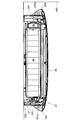
- FIG. 3 is a horizontal sectional view taken along line AA in FIG. 2.
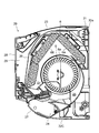
- FIG. 3 is a vertical sectional view cut along the line BB in FIG. 2.
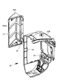
- FIG. 5 is a vertical sectional view similar to FIG. 4, showing a state of a louver different from FIG. 4. It is the same perspective view as FIG. 1, and shows the state which pushed up the opening / closing panel. It is a perspective view of the end member which constitutes a part of an indoor unit case, and the projection part attached to it.
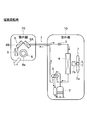
- FIGS. 11 and 12 show a basic configuration of a separate type air conditioner.
- the air conditioner depicted in FIGS. 11 and 12 uses the heat pump cycle 1 as the refrigeration cycle.
- the heat pump cycle 1 includes a compressor 2, a four-way valve 3, an outdoor heat exchanger 4, a decompression expansion device 5, and an indoor heat exchanger 6 connected in a loop.
- the compressor 2, the four-way valve 3, the outdoor heat exchanger 4, and the decompression / expansion device 5 are accommodated in a casing of the outdoor unit 10.
- the indoor heat exchanger 6 is accommodated in the housing of the indoor unit 20.
- the outdoor heat exchanger 4 functions as a condenser during cooling operation and functions as an evaporator during heating operation.
- the indoor heat exchanger 6 functions as an evaporator during cooling operation and functions as a condenser during heating operation.
- the outdoor heat exchanger 4 is combined with a blower 7 that forms an airflow passing therethrough.
- the blower 7 includes a fan 7a and a motor 7b that rotates the fan 7a.
- the fan 7a is a propeller fan.
- the indoor heat exchanger 6 is combined with a blower 8 that forms an airflow passing therethrough.
- the blower 8 includes a cross flow fan 8a arranged with its axis line horizontal and a motor (not shown) that rotates the fan.
- the indoor heat exchanger 6 is configured by combining three heat exchangers 6A, 6B, and 6C like a roof that covers the blower 8.
- the use of the three heat exchangers 6A, 6B, 6C for the indoor heat exchanger 6 is merely a configuration example, and any number of heat exchangers may be used.
- the configuration may be such that one heat exchanger is the indoor heat exchanger 6.
- FIG. 11 shows a state during cooling operation or defrosting operation.
- the high-temperature and high-pressure refrigerant discharged from the compressor 2 enters the outdoor heat exchanger 4 where it dissipates heat and condenses.
- the refrigerant that has exited the outdoor heat exchanger 4 enters the indoor heat exchanger 6 from the decompression / expansion device 5 and evaporates, takes heat from the indoor air, and returns to the compressor 2.
- the airflow generated by the blower 7 promotes heat dissipation from the outdoor heat exchanger 4, and the airflow generated by the blower 8 promotes heat absorption of the indoor heat exchanger 6.
- the air cooled by the indoor heat exchanger 6 blows out from a blower outlet (not shown) to lower the indoor temperature.
- Fig. 12 shows a state during heating.
- the four-way valve 3 is switched, and the refrigerant flow is reversed from that during the cooling operation. That is, the high-temperature and high-pressure refrigerant discharged from the compressor 2 enters the indoor heat exchanger 6 where it dissipates heat and condenses.
- the refrigerant that has exited the indoor heat exchanger 6 enters the outdoor heat exchanger 4 from the decompression / expansion device 5 and evaporates, takes in heat from the outdoor air, and returns to the compressor 2.
- the air flow generated by the blower 8 promotes heat radiation from the indoor heat exchanger 6, and the air flow generated by the blower 7 promotes heat absorption of the outdoor heat exchanger 4. Air warmed by the indoor heat exchanger 6 is blown out from a blower outlet (not shown) to raise the indoor temperature.
- the internal elements of the indoor unit 20 described above are accommodated in the indoor unit housing 20a shown in FIG.
- the indoor unit housing 20a is configured by combining a plurality of parts made of a synthetic resin injection molded product.
- the indoor unit 20 is installed above the wall surface of the room, and the indoor unit housing 20a is provided with various devices for realizing a comfortable air circulation for the user and improving the appearance. Yes. Hereinafter, this will be described with reference to FIGS.
- the indoor unit housing 20a is configured by combining a plurality of separate parts with a back member 21 serving as a base.
- the plurality of separate parts include an end member 22L that constitutes the left end of the indoor unit casing 20a, an end member 22R that constitutes the right end of the indoor unit casing 20a, and a space between the end members 22L and 22R.
- the air outlet member 22C combined with the lower front portion of the body 20a, the projecting portion 30L engaged with the end member 22L, the projecting portion 30R engaged with the end member 22R, the louver 27, and the front panel 28.
- the right end member 22R is provided with a display panel DP at the front lower portion.
- the display panel DP is provided with a display element and a display lamp for informing operation status, a light receiving window for receiving an infrared signal from a remote controller (not shown), and the like.
- an indoor heat exchanger 6 in which three heat exchangers 6A, 6B, and 6C are combined, and an indoor heat exchanger 6 are provided.
- a blower 8 that forms an airflow passing therethrough is disposed.
- the blower 8 is constituted by a cross flow fan 8a arranged with its axis line horizontal and a motor 8b (see FIG. 3) for rotating the fan.
- the rear member 21 has a suction port 23 formed on the top surface and an air outlet 24 formed on the lower front surface.
- the air outlet 24 is constituted by an air outlet member 22C.
- a ventilation path 25 is formed between the blower 8 and the outlet 24.
- a filter 26 is disposed on the windward side of the indoor heat exchanger 6.
- the filter 26 covers a region from the upper surface to the front surface of the indoor heat exchanger 6 and collects dust contained in the sucked indoor air.
- a louver 27 is arranged at the outlet 24.
- the louver 27 closes the outlet 24 as shown in FIGS. 1 and 4 when the operation of the indoor unit 20 is stopped.
- the louver 27 is moved as shown in FIG. 5 by a motor (not shown), and air is blown out from the outlet 24.
- the louver 27 may be stationary in an open state, or may swing to change the wind direction.
- the louver 27 When the indoor unit 20 is put into an operating state, the louver 27 is opened and the blower 8 is driven. In the cooling operation, the high-temperature and high-pressure refrigerant discharged from the compressor 2 is condensed in the outdoor heat exchanger 4, passes through the decompression / expansion device 5, and then enters the indoor heat exchanger 6 to evaporate. The surface of the inner heat exchanger 6 becomes a low temperature. For this reason, the air passing through the indoor heat exchanger 6 becomes cold air and blows out from the outlet 24.
- the high-temperature and high-pressure refrigerant discharged from the compressor 2 condenses in the indoor heat exchanger 6, so that the surface of the outdoor heat exchanger 6 becomes high temperature. For this reason, the air passing through the indoor heat exchanger 6 becomes warm air and blows out from the outlet 24.
- An opening / closing panel 28 that can move in the vertical direction is provided on the front surface of the rear member 21.
- the open / close panel 28 rotates about a fulcrum and takes two positions, a closed position shown in FIGS. 1 and 4 and an open position shown in FIG. 6.
- the opening 29 formed on the front surface of the back member 21 is opened, and the filter 26 is exposed.
- the filter 26 can be accessed. The user can take out the filter 26 and remove dust adhering thereto.
- the open / close panel 28 occupies the most important position among the design components of the indoor unit 20.
- the left-right width of the open / close panel 28 when viewed from the front is wider than the total width of the back member 21 and the end members 22L and 22R combined therewith.
- the left and right ends of the open / close panel 28 wrap around the left and right side surfaces of the indoor unit housing 20a and cover a part of the left and right side surfaces, as in the open / close panel of Patent Document 2. In this way, the size of the open / close panel 28 occupies most of the front shape of the indoor unit 20, and the left and right side surfaces of the indoor unit housing 20a are made inconspicuous, thereby improving the design.
- Projections 30L and 30R are formed on the left and right side surfaces of the indoor unit housing 20a at the same height as the open / close panel 28 in the closed state.
- the protruding heights of the protrusions 30L and 30R from the left and right side surfaces of the indoor unit housing 20a are set to be substantially the same as the protruding lengths of the left and right ends of the open / close panel 28 from the left and right side surfaces of the indoor unit housing 20a.
- the vertical widths of the protrusions 30L and 30R are set to be substantially the same as the vertical width of the open / close panel 28.
- the left and right ends of the open / close panel 28 are in close contact with the edges of the projecting portions 30L and 30R or approached to a grazing distance. That is, the protrusions 30L and 30R function as a structure that is continuous with the open / close panel 28 in the closed state.
- the projecting portions 30L and 30R are formed with slopes 30La and 30Ra that connect the end portions of the open / close panel 28 and the side surfaces of the end members 22L and 22R.
- the horizontal cross-sectional shapes of the protrusions 30L and 30R are substantially triangular as shown in FIG.
- the projecting portions 30L and 30R exist as structures that bridge the end portions of the open / close panel 28 and the side surfaces of the end members 22L and 22R, so that the open / close panel 28 was cut off suddenly at the end portions. The feeling is lost and the design is further improved.
- the protrusions 30L and 30R are configured as separate parts attached to the end members 22L and 22R.
- FIG. 7 shows a combination of the end member 22R and the protrusion 30R.
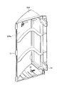
- the structure of the protrusion 30R can be easily understood with reference to the enlarged perspective view of FIG.
- the three claws 31 are formed on the edge of the projecting portion 30R facing the back side of the indoor unit 20 at intervals in the vertical direction.
- the end member 22 ⁇ / b> R is formed with an engagement hole 32 for engaging the claw 31 at a position corresponding to the claw 31.
- a protruding piece 33 is formed on the edge of the protruding portion 30R facing the front side of the indoor unit 20 at a position close to the upper end and a position close to the lower end.
- a through hole 34 is formed at a position corresponding to the protruding piece 33 in the end member 22R.
- FIG. 3 shows a state where the indoor unit 20 is installed close to the right wall surface WR. Between the right side surface of the indoor unit 20 and the wall surface WR, a distance equal to the protruding height of the protruding portion 30R from the right side surface is kept at a minimum. For this reason, the air blown out from the blower outlet 24 is sufficiently far away from the indoor unit 20 before hitting the wall surface WR and stalling. This reduces the occurrence of short circuits.
- the indoor unit 20 When the indoor unit 20 is placed on the floor of the room where the assembly line conveyor, work table, indoor unit 20 is mounted, etc., the protrusions protruded from the left and right side surfaces of the indoor unit housing 20a
- the indoor unit 20 can be easily lifted by placing a finger on the portions 30L and 30R.
- the handling of the indoor unit 20 is further facilitated by using the projecting portions 30L and 30R as the finger hanging portions. Since the projecting portions 30L and 30R are engaged with the claws 31 by the end members 22L and 22R and the projecting piece 33 is screwed to the projecting portions 30L and 30R, the projecting portions 30L and 30R will not come off even if a finger is put on them.
- the indoor unit 20 can be configured in many models with different sizes and designs by changing the combination of the end members 22L and 22R or the outlet member 22C combined with the back member 21. Since the protrusions 30L and 30R are separate parts, the variety of models can be increased by replacing the protrusions 30L and 30R.
- the height at which the protrusions 30L and 30R protrude from the left and right side surfaces of the indoor unit housing 20a does not necessarily have to be the same on the left and right. It is also possible to change the protruding height on the left and right, and to create an asymmetric design.
- the protrusions 30L and 30R are configured as separate members that engage with the end members 22L and 22R.
- the protrusions 30L and 30R may be integrally formed with the end members 22L and 22R without using the protrusions 30L and 30R as separate members. Good.
- FIG. 9 and FIG. 10 show a second embodiment of the present invention.
- the indoor air suction path is improved.
- FIG. 9 shows the protrusion 30R.
- a vent hole 36a and a vent hole 36b are formed in the slope 30Ra of the projecting portion 30R and the front face 30Rb facing the back face of the open / close panel 28.
- Each of the air holes 36a and 36b is composed of a plurality of slits.
- the air hole 36a communicates with the air hole 36b through the internal space of the protrusion 30R.
- the vent hole 36 b communicates with the windward space of the filter 26 from the back side of the open / close panel 28. That is, the vent hole 36 a communicates with the windward space of the filter 26 from the back side of the open / close panel 28.
- the protruding portion 30L side has the same structure.
- the space behind the open / close panel 28 becomes negative pressure.
- the room air is not only from the top suction port 23 of the back member 21 but also from the back side of the protrusions 30L and 30R through the air holes formed in the protrusions 30L and 30R as shown by the arrow S in FIG. Is also inhaled.
- the position of the opening part into which air is sucked in is dispersed, and the total area of the opening part is increased, whereby the ventilation resistance of the indoor unit 20 is reduced and the blowing efficiency is improved.
- the present invention is widely applicable to separate type air conditioners.
Landscapes
- Engineering & Computer Science (AREA)
- Chemical & Material Sciences (AREA)
- Combustion & Propulsion (AREA)
- Mechanical Engineering (AREA)
- General Engineering & Computer Science (AREA)
- Air Filters, Heat-Exchange Apparatuses, And Housings Of Air-Conditioning Units (AREA)
- Air-Conditioning Room Units, And Self-Contained Units In General (AREA)
Abstract
Selon l'invention, un boîtier d'unité intérieure (20a) d'une unité intérieure (20) est constitué par la combinaison d'éléments de bord (22G, 22D) sur les côtés gauche et droit d'un élément de face arrière (21). Des parties saillantes (30G, 30D) sont attachées aux éléments de bord sous la forme de composants séparés. Les parties saillantes servent à maintenir une distance qui n'est pas inférieure à une distance prédéterminée entre une surface de paroi dirigée vers des surfaces latérales de l'unité intérieure sur lesquelles sont disposées les parties saillantes et les surfaces latérales. Un panneau d'ouverture et de fermeture (28) apte à se déplacer vers le haut et vers le bas est disposé sur une surface avant du boîtier d'unité intérieure. Les bords gauche et droit du panneau d'ouverture et de fermeture s'enroulent autour des surfaces latérales gauche et droite du boîtier d'unité intérieure, et les parties saillantes jouent le rôle de parties structurelles reliées au panneau d'ouverture et de fermeture.
Applications Claiming Priority (2)
| Application Number | Priority Date | Filing Date | Title |
|---|---|---|---|
| JP2011038812A JP2012172959A (ja) | 2011-02-24 | 2011-02-24 | 空気調和機 |
| JP2011-038812 | 2011-02-24 |
Publications (1)
| Publication Number | Publication Date |
|---|---|
| WO2012114841A1 true WO2012114841A1 (fr) | 2012-08-30 |
Family
ID=46720629
Family Applications (1)
| Application Number | Title | Priority Date | Filing Date |
|---|---|---|---|
| PCT/JP2012/052333 Ceased WO2012114841A1 (fr) | 2011-02-24 | 2012-02-02 | Climatiseur |
Country Status (2)
| Country | Link |
|---|---|
| JP (1) | JP2012172959A (fr) |
| WO (1) | WO2012114841A1 (fr) |
Cited By (1)
| Publication number | Priority date | Publication date | Assignee | Title |
|---|---|---|---|---|
| EP3076096A4 (fr) * | 2013-11-26 | 2017-02-01 | Daikin Industries, Ltd. | Unité intérieure |
Citations (14)
| Publication number | Priority date | Publication date | Assignee | Title |
|---|---|---|---|---|
| JPS56109520U (fr) * | 1980-01-25 | 1981-08-25 | ||
| JPS5775322U (fr) * | 1980-10-24 | 1982-05-10 | ||
| JPS61502326A (ja) * | 1984-06-07 | 1986-10-16 | コウ、トマス・ユ− | 基板媒体キャリヤ |
| JPS6245409U (fr) * | 1985-09-06 | 1987-03-19 | ||
| JPH06221610A (ja) * | 1993-01-28 | 1994-08-12 | Sanyo Electric Co Ltd | 空気調和機 |
| JPH0894117A (ja) * | 1994-09-26 | 1996-04-12 | Daikin Ind Ltd | 天吊式空気調和機のケーシング構造 |
| WO2002103251A2 (fr) * | 2001-06-19 | 2002-12-27 | Lg Electronics Inc. | Conditionneur d'air |
| JP2004163077A (ja) * | 2002-11-11 | 2004-06-10 | Samsung Electronics Co Ltd | 空気調和機 |
| JP2004337794A (ja) * | 2003-05-19 | 2004-12-02 | Okuma Corp | ろ過装置 |
| JP2005283069A (ja) * | 2004-03-31 | 2005-10-13 | Fujitsu General Ltd | 空気調和機 |
| JP2006340336A (ja) * | 2005-06-02 | 2006-12-14 | Sharp Corp | 表示装置 |
| JP2010151333A (ja) * | 2008-12-24 | 2010-07-08 | Toshiba Carrier Corp | 空気調和機の室内機 |
| JP2010196976A (ja) * | 2009-02-25 | 2010-09-09 | Sanyo Electric Co Ltd | 農事用空気調和装置 |
| JP2011021878A (ja) * | 2010-10-15 | 2011-02-03 | Daikin Industries Ltd | 空気調和機 |
Family Cites Families (3)
| Publication number | Priority date | Publication date | Assignee | Title |
|---|---|---|---|---|
| JP3175197B2 (ja) * | 1991-07-10 | 2001-06-11 | 松下電器産業株式会社 | 機器のフロントパネル取付装置 |
| JP3121505B2 (ja) * | 1994-11-02 | 2001-01-09 | 三菱電機株式会社 | 空気調和機 |
| JP4924696B2 (ja) * | 2009-11-04 | 2012-04-25 | ダイキン工業株式会社 | 壁掛け型室内機 |
-
2011
- 2011-02-24 JP JP2011038812A patent/JP2012172959A/ja not_active Ceased
-
2012
- 2012-02-02 WO PCT/JP2012/052333 patent/WO2012114841A1/fr not_active Ceased
Patent Citations (14)
| Publication number | Priority date | Publication date | Assignee | Title |
|---|---|---|---|---|
| JPS56109520U (fr) * | 1980-01-25 | 1981-08-25 | ||
| JPS5775322U (fr) * | 1980-10-24 | 1982-05-10 | ||
| JPS61502326A (ja) * | 1984-06-07 | 1986-10-16 | コウ、トマス・ユ− | 基板媒体キャリヤ |
| JPS6245409U (fr) * | 1985-09-06 | 1987-03-19 | ||
| JPH06221610A (ja) * | 1993-01-28 | 1994-08-12 | Sanyo Electric Co Ltd | 空気調和機 |
| JPH0894117A (ja) * | 1994-09-26 | 1996-04-12 | Daikin Ind Ltd | 天吊式空気調和機のケーシング構造 |
| WO2002103251A2 (fr) * | 2001-06-19 | 2002-12-27 | Lg Electronics Inc. | Conditionneur d'air |
| JP2004163077A (ja) * | 2002-11-11 | 2004-06-10 | Samsung Electronics Co Ltd | 空気調和機 |
| JP2004337794A (ja) * | 2003-05-19 | 2004-12-02 | Okuma Corp | ろ過装置 |
| JP2005283069A (ja) * | 2004-03-31 | 2005-10-13 | Fujitsu General Ltd | 空気調和機 |
| JP2006340336A (ja) * | 2005-06-02 | 2006-12-14 | Sharp Corp | 表示装置 |
| JP2010151333A (ja) * | 2008-12-24 | 2010-07-08 | Toshiba Carrier Corp | 空気調和機の室内機 |
| JP2010196976A (ja) * | 2009-02-25 | 2010-09-09 | Sanyo Electric Co Ltd | 農事用空気調和装置 |
| JP2011021878A (ja) * | 2010-10-15 | 2011-02-03 | Daikin Industries Ltd | 空気調和機 |
Cited By (2)
| Publication number | Priority date | Publication date | Assignee | Title |
|---|---|---|---|---|
| EP3076096A4 (fr) * | 2013-11-26 | 2017-02-01 | Daikin Industries, Ltd. | Unité intérieure |
| AU2014355764B2 (en) * | 2013-11-26 | 2017-10-26 | Daikin Industries, Ltd. | Indoor unit |
Also Published As
| Publication number | Publication date |
|---|---|
| JP2012172959A (ja) | 2012-09-10 |
Similar Documents
| Publication | Publication Date | Title |
|---|---|---|
| KR101640411B1 (ko) | 공기조화기 | |
| WO2013108658A1 (fr) | Climatiseur | |
| WO2014178166A1 (fr) | Panneau décoratif et unité intérieure de climatiseur comprenant celui-ci | |
| JP2007192480A (ja) | 空気調和機 | |
| KR20050022680A (ko) | 에어컨 실내기 | |
| JP6942082B2 (ja) | 一体型空気調和機 | |
| JP6075088B2 (ja) | 空気調和機 | |
| JP5773674B2 (ja) | 空気調和機の室内機 | |
| JP4708199B2 (ja) | 空気調和機 | |
| JP2012172959A (ja) | 空気調和機 | |
| JP2015218993A (ja) | 空気調和機 | |
| JP5803974B2 (ja) | 化粧パネル及びそれを備えた空気調和機の室内ユニット | |
| JP2013127363A (ja) | 空気調和機 | |
| JP6081955B2 (ja) | 空気調和機 | |
| KR101328531B1 (ko) | 에어컨 및 냉동장치용 실외기의 전면커버 | |
| JP2012042208A (ja) | 空気調和機 | |
| CN206890682U (zh) | 一种柜式上进风空调 | |
| CN1766431B (zh) | 空调机 | |
| KR100613513B1 (ko) | 일체형 공기조화기 | |
| KR100750233B1 (ko) | 패키지 에어컨의 디스플레이용 인쇄회로기판 체결구조 | |
| KR100412415B1 (ko) | 에어컨의 흡입구조 | |
| KR200312147Y1 (ko) | 룸 에어컨의 구조 | |
| JP2019066147A (ja) | 床置型空気調和機 | |
| KR20020090602A (ko) | 공기흡입커버를 구비한 패키지 에어컨 실내기 | |
| KR100563528B1 (ko) | 공기조화기 |
Legal Events
| Date | Code | Title | Description |
|---|---|---|---|
| 121 | Ep: the epo has been informed by wipo that ep was designated in this application |
Ref document number: 12749962 Country of ref document: EP Kind code of ref document: A1 |
|
| NENP | Non-entry into the national phase |
Ref country code: DE |
|
| 122 | Ep: pct application non-entry in european phase |
Ref document number: 12749962 Country of ref document: EP Kind code of ref document: A1 |