WO2012114947A1 - Dispositif d'holographie numérique et procédé de génération d'image utilisant une holographie numérique - Google Patents
Dispositif d'holographie numérique et procédé de génération d'image utilisant une holographie numérique Download PDFInfo
- Publication number
- WO2012114947A1 WO2012114947A1 PCT/JP2012/053436 JP2012053436W WO2012114947A1 WO 2012114947 A1 WO2012114947 A1 WO 2012114947A1 JP 2012053436 W JP2012053436 W JP 2012053436W WO 2012114947 A1 WO2012114947 A1 WO 2012114947A1
- Authority
- WO
- WIPO (PCT)
- Prior art keywords
- hologram
- region
- intensity
- average value
- regions
- Prior art date
- Legal status (The legal status is an assumption and is not a legal conclusion. Google has not performed a legal analysis and makes no representation as to the accuracy of the status listed.)
- Ceased
Links
Images


Classifications
-
- G—PHYSICS
- G03—PHOTOGRAPHY; CINEMATOGRAPHY; ANALOGOUS TECHNIQUES USING WAVES OTHER THAN OPTICAL WAVES; ELECTROGRAPHY; HOLOGRAPHY
- G03H—HOLOGRAPHIC PROCESSES OR APPARATUS
- G03H1/00—Holographic processes or apparatus using light, infrared or ultraviolet waves for obtaining holograms or for obtaining an image from them; Details peculiar thereto
- G03H1/04—Processes or apparatus for producing holograms
- G03H1/0443—Digital holography, i.e. recording holograms with digital recording means
-
- G—PHYSICS
- G01—MEASURING; TESTING
- G01B—MEASURING LENGTH, THICKNESS OR SIMILAR LINEAR DIMENSIONS; MEASURING ANGLES; MEASURING AREAS; MEASURING IRREGULARITIES OF SURFACES OR CONTOURS
- G01B11/00—Measuring arrangements characterised by the use of optical techniques
- G01B11/24—Measuring arrangements characterised by the use of optical techniques for measuring contours or curvatures
-
- G—PHYSICS
- G03—PHOTOGRAPHY; CINEMATOGRAPHY; ANALOGOUS TECHNIQUES USING WAVES OTHER THAN OPTICAL WAVES; ELECTROGRAPHY; HOLOGRAPHY
- G03H—HOLOGRAPHIC PROCESSES OR APPARATUS
- G03H1/00—Holographic processes or apparatus using light, infrared or ultraviolet waves for obtaining holograms or for obtaining an image from them; Details peculiar thereto
- G03H1/04—Processes or apparatus for producing holograms
- G03H1/08—Synthesising holograms, i.e. holograms synthesized from objects or objects from holograms
- G03H1/0866—Digital holographic imaging, i.e. synthesizing holobjects from holograms
-
- G—PHYSICS
- G03—PHOTOGRAPHY; CINEMATOGRAPHY; ANALOGOUS TECHNIQUES USING WAVES OTHER THAN OPTICAL WAVES; ELECTROGRAPHY; HOLOGRAPHY
- G03H—HOLOGRAPHIC PROCESSES OR APPARATUS
- G03H1/00—Holographic processes or apparatus using light, infrared or ultraviolet waves for obtaining holograms or for obtaining an image from them; Details peculiar thereto
- G03H1/04—Processes or apparatus for producing holograms
- G03H1/0443—Digital holography, i.e. recording holograms with digital recording means
- G03H2001/0454—Arrangement for recovering hologram complex amplitude
- G03H2001/0458—Temporal or spatial phase shifting, e.g. parallel phase shifting method
-
- G—PHYSICS
- G03—PHOTOGRAPHY; CINEMATOGRAPHY; ANALOGOUS TECHNIQUES USING WAVES OTHER THAN OPTICAL WAVES; ELECTROGRAPHY; HOLOGRAPHY
- G03H—HOLOGRAPHIC PROCESSES OR APPARATUS
- G03H2222/00—Light sources or light beam properties
- G03H2222/31—Polarised light
Definitions
- a single hologram including two or more types of hologram information that is recorded in each pixel of an image sensor to which a polarizer array is mounted and has different phase shift amounts of reference light is converted into a polarizer array. It is defined as a hologram.
- the present invention provides a digital holography device for generating a reproduced image of a subject based on a first hologram and a second hologram obtained by extracting components having the same phase shift amount from the polarizer array hologram, and an image generation method using digital holography About.
- the unit of phase is expressed in radians.
- advanced measurement and analysis of the three-dimensional shape of an object is required, and various measurement methods have been developed.
- interference measurement technology using light interference, particularly digital holography can obtain three-dimensional information of an object in a non-contact and non-destructive manner. It has become one.
- Digital holography is a technique for reproducing an image of a three-dimensional object using a computer from an interference pattern (interference fringes) obtained by light irradiation on the three-dimensional object.
- an interference pattern formed by object light obtained by light irradiation on a three-dimensional object and reference light that is coherent with the object light is represented by an image sensor such as a CCD (charge-coupled device).
- CCD charge-coupled device
- the present inventors attach a polarizer array that divides the light emitted from the light source into two types of reference lights having different phases on a plane perpendicular to the traveling direction, and attaches it to the imaging surface of the CCD camera.
- a digital holography device has been proposed that improves the image quality of a reproduced image of a subject by one shooting (Patent Document 1).
- the inventors of the present invention split the object light into two types of object lights having different polarization directions and generate an angle difference in each propagation direction, and the first polarizer region and the second polarizer region.
- a polarizer array unit that transmits the reference light and the object light that reaches through the subject is provided, thereby obtaining highly accurate three-dimensional information of a deep depth range at that moment by one imaging.
- a digital holography device that can be used is proposed (Patent Document 2).
- An object of the present invention is to provide a digital holography device capable of completely removing unnecessary zero-order diffracted light caused by an assembly error between a polarizer array and an imaging surface of a CCD camera, and an image generation method using digital holography. There is to do.
- a digital holography device includes two or more types of hologram information recorded in pixels of an image sensor on which a polarizer array is mounted and having different phase shift amounts of reference light.
- a hologram generating unit for generating a first hologram and a second hologram generated by extracting components having the same phase shift amount from a polarizer array hologram, and dividing the first hologram into a plurality of first regions,
- a division unit that divides the second hologram into a plurality of second regions by the same division pattern as the division pattern of the plurality of first regions; a first average value of intensity in the first region of the first hologram;
- a comparison unit that compares a second average value of intensity in a second region corresponding to the first region of two holograms, and the first average value and the second average value, At least one of the intensity in the first region of the first hologram and the intensity in the second region corresponding to the first region of the second hologram so that
- the first average value of the intensity in the first region of the first hologram is different from the second average value of the intensity in the second region corresponding to the first region of the second hologram. And correcting at least one of the intensity in the first area of the first hologram and the intensity in the second area corresponding to the first area of the second hologram, so that the zero-order diffracted light in each area of each hologram is corrected.
- the intensity ratio can be set to 1: 1, and the 0th-order diffracted light, which is an unnecessary image component, can be accurately removed from the entire image sensor surface to correct intensity unevenness, and the subject can be measured with high accuracy.
- An image generation method by digital holography according to the present invention is recorded on a pixel of an imaging device to which a polarizer array is attached, and from a polarizer array hologram including two or more types of hologram information having different phase shift amounts of reference light.
- a hologram generation step for generating a first hologram and a second hologram generated by extracting components having the same phase shift amount, and dividing the first hologram into a plurality of first regions, A division step of dividing into a plurality of second regions by the same division pattern as the division pattern of the first region, a first average value of the intensity in the first region of the first hologram, and the first of the second hologram A comparison step of comparing the second average value of the intensity in the second region corresponding to the region, the first average value and the second average And the intensity in the first region of the first hologram and the intensity in the second region corresponding to the first region of the second hologram so that the zero-order diffracted light intensity is accurately removed when And a correction step for correcting at least one of them.
- Another digital holography device is a polarizer array hologram including two or more types of hologram information recorded in pixels of an image sensor to which a polarizer array is mounted and having different phase shift amounts of reference light.
- a hologram generation unit that generates a first hologram and a second hologram generated by extracting components having the same phase shift amount, and a first hologram that is divided into a plurality of first regions, and the second hologram is divided into the plurality of The intensity of at least one of the division unit that divides into a plurality of second regions by the same division pattern as the division pattern of the first region, the first region of the first hologram, and the second region of the second hologram Based on the first and second holograms while changing the correction value, a plurality of reconstructed images are obtained by calculation of the phase shift method and diffraction integration.
- a selection unit that selects a reproduction image with the smallest superposition of zero-order diffracted light from the plurality of reproduction image groups and
- This feature makes it possible to obtain a reconstructed image correction value that minimizes the superposition of the 0th-order diffracted light, so that the 0th-order diffracted light intensity can be more accurately removed.
- An image generation method by digital holography according to the present invention is recorded on a pixel of an imaging device to which a polarizer array is attached, and from a polarizer array hologram including two or more types of hologram information having different phase shift amounts of reference light.
- a hologram generation step for generating a first hologram and a second hologram generated by extracting components having the same phase shift amount, and dividing the first hologram into a plurality of first regions, Intensity in at least one of the division step of dividing into a plurality of second areas by the same division pattern as the division pattern of the first area, and the first area of the first hologram and the second area of the second hologram While changing the correction value, the calculation and diffraction of the phase shift method based on the first and second holograms
- a reconstructed image group generating step for generating a plurality of reconstructed image groups according to the minutes, and a selection for selecting the reconstructed image with the minimum superposition of the 0th-order diffracted light from the plurality of reconstructed image groups and obtaining the correction value of the selected reconstructed image And a step.
- the digital holography device compares a first average value of intensity in the first region of the first hologram and a second average value of intensity in the second region corresponding to the first region of the second hologram. And correcting at least one of the first region of the first hologram and the second region corresponding to the first region of the second hologram so that the 0th-order diffracted light intensity is accurately removed Since the correction unit is provided, the intensity ratio of the 0th-order diffracted light can be 1: 1 in each area of each hologram, and the 0th-order diffracted light, which is an unnecessary image component, can be accurately removed from the entire image sensor surface. Thus, the intensity unevenness can be corrected and the subject can be measured with high accuracy.
- FIG. 6 is a diagram schematically showing a configuration of another digital holography device according to an embodiment.
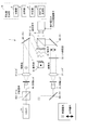
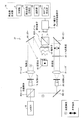
- FIG. 1 is a diagram schematically illustrating a configuration of a digital holography device 1 according to an embodiment.
- the digital holography device 1 is a system for realizing parallel two-stage phase shift digital holography.
- FIG. 1 shows an example of an optical system when the polarizer array 6 is mounted on the imaging surface of the imaging device 7.
- the digital holography device 1 shown in FIG. 1 will be described. First, it is assumed that the laser emitted from the light source 15 has only a vertical polarization component. The light emitted from the light source 15 is divided into object light and reference light by the beam splitting element BS1.
- the object light transmitted through the beam splitting element BS1 passes through the objective lens 16 and the lens 17, is reflected by the mirror M1, and is irradiated onto the subject 18.
- Scattered light from the subject 18 passes through the polarizer 19 and becomes vertically polarized light.
- the scattered light passes through the beam combining element BS2, passes through the polarizer array 6, and reaches the imaging surface of the imaging element 7.
- the reference light reflected by the beam splitting element BS1 is reflected by the mirror M2, passes through the objective lens 20 and the lens 21, and has a component of vertical polarization and horizontal polarization when passing through the quarter wavelength plate 22. It becomes a circularly polarized light. At this time, the reference light has a component without phase shift and a component shifted by - ⁇ / 2 phase. Then, the reference light is reflected by the mirror M3, is reflected by the beam combining element BS2, and reaches the image sensor 7 that is integrated with the polarizer array 6.
- the object light and the reference light that have passed through the polarizer array 6 interfere on the imaging surface of the imaging device 7.
- the phase of the reference light that has passed through the polarizer array 6 has two types of information spatially and is distributed in a checkered pattern.
- the interference between the reference light and the object light makes it possible to capture information on two types of holograms at a time.
- the digital holography device 1 includes a reproduction image generator 14.
- the reproduction image generator 14 includes a hologram generation unit 26 that generates a hologram 9 and a hologram 10 (FIG. 4) generated by extracting components having the same phase shift amount from the polarizer array hologram 8 (FIG. 4), a hologram 9 is divided into a plurality of regions 11 (FIG. 9), and the hologram 10 is divided into a plurality of regions 12 (FIG.
- the comparison unit 4 that compares the first average value of the intensity and the second average value of the intensity in the corresponding region 12 of the hologram 10, the zero-order diffracted light
- the correction unit 5 corrects at least one of the first average value and the second average value so that the intensity is accurately removed.
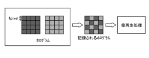
- FIG. 2 is a diagram for explaining the principle of parallel phase shift digital holography, which is a digital holography apparatus 1 capable of realizing phase shift interference measurement with a single shot.
- the digital holography device 1 records information of a plurality of holograms necessary for the phase shift method by a single imaging using a single imaging element 7. Then, a three-dimensional image of the subject is reproduced by image reproduction processing.
- FIG. 2 shows the principle of parallel two-stage phase shift digital holography, which is parallel phase shift digital holography in which two holograms are acquired by one imaging.
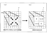
- FIG. 3A is a diagram showing a transmission axis in each cell of the polarizer array 6 provided in the digital holography device 1
- FIG. 3B is a diagram showing a phase distribution of reference light in the digital holography device 1. is there.
- the arrow in FIG. 3A indicates that only polarized light in the direction of the arrow in the figure can pass.
- the size of one section of the polarizer array 6 corresponds to the size of one pixel on the imaging surface of the imaging device 7, and the polarizer array 6 is mounted on the imaging surface of the imaging device 7.
- the polarizer array 6 divides the light emitted from the light source 15 into two types of reference lights having different phases on a plane perpendicular to the traveling direction.
- the transmission axis in each cell of the polarizer array 6 is configured as shown in FIG. 3A, the phase distribution of the reference light recorded in each pixel on the imaging surface of the imaging device 7 is as shown in FIG. As shown in FIG.
- the distribution is such that regions where the phase shift is zero and regions where the phase shift is ⁇ / 2 are alternately arranged. Therefore, the polarizer array 6 can obtain the polarizer array hologram 8 (FIG. 4) including two types of hologram information having different phase shift amounts of the reference light by one recording.
- FIG. 4 is a diagram for explaining an image reproduction algorithm by the digital holography device 1.
- the hologram generator 26 provided in the reconstructed image generator 14 of the digital holography device 1 has interference fringes with the same phase shift amount of the reference light from one polarizer array hologram 8 recorded on the imaging surface of the imaging device 7.
- a hologram 23 and a hologram 24 representing information are extracted.
- interpolation processing is performed on each missing pixel I5 of the hologram 23 and the hologram 24 using the adjacent pixels I1, I2, I3, and I4, and two holograms 9 and 10 are obtained.
- calculation processing is performed by the two-stage phase shift method using the obtained holograms 9 and 10.
- a reproduction image is obtained by performing diffraction calculation on the complex amplitude of the subject 18 obtained by the calculation.
- FIG. 5 is a photograph showing the subject imaged by the digital holography apparatus. Experiments were performed using the optical system shown in FIG. The subject used for the experiment is shown in FIG. The subject is a miniature model of a car. A solid-state laser having a wavelength of 532 nm was used as the light source 15, and a CCD camera with a polarizer array having a number of pixels of 1164 (H) ⁇ 874 (V) was used as the image sensor 7.
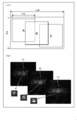
- FIG. 7A is a diagram showing a hologram recorded by an image sensor of a conventional digital holography device and a range of pixels used for image reproduction
- FIG. 7B is a diagram showing each range shown in FIG. It is a figure which shows the 0th-order diffracted light in.
- FIG. 7A shows a 1164 ⁇ 874-pixel electronic hologram recorded by the image sensor and a range of pixels used for image reproduction.
- FIG. 7B shows the result of image reproduction using the 512 ⁇ 512 pixels from the left in the range indicated by the symbols A, B, and C in FIG. 7A.
- Zero-order diffracted light is represented in the area A1, the area B1, and the area C1 surrounded by the square and the enlarged views thereof.
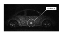
- the 0th-order diffracted light is superimposed on any reproduced image, but when the enlarged view is observed, the 0th-order diffracted light is partially removed. It can also be seen that the removal and superposition changes when the range of pixels used for image reproduction is changed. From the above, it has been clarified that the appearance of the 0th-order diffracted light changes when the range of the hologram used for image reproduction is changed.
- FIG. 7B shows that the intensity of the 0th-order diffracted light can be made constant only on a part of the imaging surface of the imaging element, and the intensity variation has occurred in other parts.
- FIG. 8 is a diagram for explaining an alignment error when the polarizer array and the image sensor are mounted.
- One of the reasons why it is difficult to make the intensity of the 0th-order diffracted light constant is the alignment error between each cell of the array of minute optical elements and each pixel of the image sensor.
- One method for solving such a problem of intensity unevenness is to more accurately mount each cell of the polarizer array 6 and each pixel of the image sensor 7.
- the size of each cell and each pixel is in the micron order in recent years, and very high-precision alignment is required.
- the alignment of the polarizer array 6 has been realized by recent improvements in manufacturing technology, a perfect one-to-one alignment between each cell of the polarizer array 6 of the optical element and each pixel of the image sensor 7 is Extremely difficult.
- the present inventors have invented a zero-order diffracted light removal algorithm in order to solve the problem of intensity unevenness by image processing.
- This algorithm has unevenness in intensity such as alignment error between the polarizer array 6 and the image sensor 7, adjustment error of the optical system, difference in light receiving sensitivity for each pixel of the image sensor, dark current, and other incidental pixel value changes. It is effective against the cause of
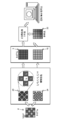
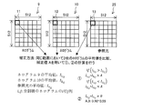
- FIG. 9 is a diagram for explaining a method of correcting the intensity of the hologram area by the digital holography apparatus 1.
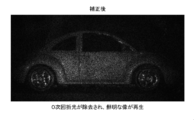
- the 0th-order diffracted light intensity varies in a plurality of types of holograms, the 0th-order diffracted light could not be calculated accurately and could not be removed. Further, by changing the intensity unevenness correction value for each hologram area, the intensity of the 0th-order diffracted light on the entire imaging surface of the imaging element 7 is made constant.
- the dividing unit 3 of the reproduced image generator 14 divides the hologram 9 into 36 regions 11 of 6 rows ⁇ 6 columns, and the hologram 10 has the same 6 rows as the division pattern of the hologram 9. It is divided into 36 regions 12 of 6 columns.
- the dividing unit 3 further divides the reference beam 25 into 36 regions 13 of 6 rows ⁇ 6 columns.
- the aspect of division shown in FIG. 9 is an example, and the present invention is not limited to this.
- the number of divisions may be larger or smaller than this. It may be divided into 16 regions of 4 rows ⁇ 4 rows, or may be divided into 64 regions of 8 rows ⁇ 8 columns. Further, it may not be divided into a matrix.
- the algorithm according to the present embodiment is applied irregularly in various ways, such as applying the algorithm according to this embodiment only where the intensity unevenness occurs. It is possible to apply the present invention even when taking a wide range.
- the two holograms 9 and 10 and the reference beam 25 obtained after the interpolation processing are divided into a plurality of regions, respectively, and correction is performed on each region.
- the comparison unit 4 of the reproduced image generator 14 compares the first average value of the intensity in the region 11 of the hologram 9 and the second average value of the intensity in the corresponding region 12 of the hologram 10. That is, the comparison unit 4 calculates and compares the average values in the corresponding regions 11 and 12 of the two holograms 9 and 10 after the interpolation processing.
- the correction unit 5 performs the first average value and the second average value.
- the first average value is corrected so that the values are equal. That is, the correction value A is given to the larger average value as a result of the comparison.
- the calculation method is as follows.
- the correction value A was about 0.90 to 0.99 this time.
- the first average value of the intensity in the region 11 of the hologram 9 is larger than the second average value of the intensity in the corresponding region 12 of the hologram 10.
- the first average value and the second average value may be corrected so that the first average value and the second average value are equal, or the first average value and the second average value are equal. Both the region 11 of the hologram 9 and the region 12 corresponding to the region 11 of the hologram 10 may be corrected.
- the present invention is not limited to this. What is necessary is just to correct
- strength may be removed correctly.
- the effect of the present invention can be achieved by correcting so that the 0th-order diffracted light intensity is accurately removed.
- the correction value B is given to the reference light intensity.
- the calculation method is as follows.
- I r — ij Average value of intensity in the region 13 of the reference beam 25
- Ir_ij_hosei intensity after correction in the region 13 of the reference beam 25
- the correction value B was about 0.90 to 0.99 this time. In this way, the intensity is adjusted for each region so that the 0th-order diffracted light is removed.
- the correction value B can be calculated, for example, based on the intensity of reference light measured in advance.
- FIG. 11 is a diagram schematically showing the configuration of the digital holography device 27 according to the embodiment.
- the same components as those described above are denoted by the same reference numerals, and detailed description thereof is omitted.
- the digital holography device 27 includes a reproduced image generator 14.
- the reproduction image generator 14 includes a hologram generation unit 26, a division unit 3, a reproduction image group generation unit 28, and a selection unit 29.
- the first average value and the second average value are not compared, and at least one of the region 11 of the hologram 9 and the region 12 corresponding to the region 11 of the hologram 10 is corrected or Instead of correcting both, the phase shift method may be calculated and a reproduced image may be obtained by diffraction integration.
- a reproduction image group is obtained by reproducing an image while changing a correction value for at least one of the region 11 and the region 12. Then, by comparing the superposition of the 0th-order diffracted light in the reproduced image group, an optimum correction value in at least one of the region 11 when the superposition of the 0th-order diffracted light is the smallest and the region 12 corresponding to the region 11 is obtained. Ask. Similarly, the intensity unevenness may be corrected by obtaining an optimal correction value in each region, and the 0th-order diffracted light may be accurately removed.
- This method is a method of removing the 0th-order diffracted light intensity more accurately by increasing labor than the method of comparing the average values shown in FIG.
- the procedure is as follows. (1) First, the procedure up to image reproduction is repeatedly executed while changing the correction value in a certain region (for example, the region in the first row and the first column). (2) Then, the obtained plurality of reproduced images are compared, the reproduced image when the superposition of the 0th-order diffracted light is the smallest is selected, and the correction value corresponding to the selected reproduced image is adopted.
- the determination that the superposition of the 0th-order diffracted light is small as shown in (2) above can be made because the value of the pixel (see FIG. 7) that appears when the 0th-order diffracted light intensity is superimposed in the reproduced image is small. . Although it takes more time to execute than the method described above in the embodiment, the zero-order diffracted light intensity can be more accurately removed.
- the hologram generation unit 26 records the phase shift amount from the polarizer array hologram 8 that is recorded on the pixel of the image sensor 7 to which the polarizer array 6 is mounted and includes two or more types of hologram information having different phase shift amounts of the reference light. Generate a hologram 9 and a hologram 10 generated by extracting the same components.
- the dividing unit 3 divides the hologram 9 into a plurality of regions 11 and divides the hologram 10 into a plurality of regions 12 by the same division pattern as the division pattern of the plurality of regions 11.
- the reconstructed image group generation unit 28 performs phase shift calculation and diffraction integration based on the holograms 9 and 10 while changing the intensity correction value in at least one of the region 11 of the hologram 9 and the region 12 of the hologram 10. A plurality of reproduced image groups are generated.
- the selection unit 29 selects a reproduced image with the smallest superposition of 0th-order diffracted light from a plurality of reproduced image groups, and obtains a correction value for the selected reproduced image.
- a polarizer array hologram including two types of hologram information has been described.
- the present invention is not limited to this.
- the present invention can also be applied to a polarizer array hologram including three or more types of hologram information.
- the present invention can be applied to a hologram including four types of hologram information.
- the present inventors proposed an intensity correction algorithm in phase shift digital holography, and confirmed its effectiveness through experiments.
- This intensity correction algorithm can be applied regardless of the number of phase shift stages in phase shift digital holography.
- This intensity correction algorithm enables high quality imaging in parallel phase shift digital holography.
- the present intensity correction algorithm achieves high-accuracy three-dimensional measurement by accurately removing unnecessary image components in a form using a micro polarizer array of parallel phase shift digital holography.
- an image sensor in which the sections of the micropolarizer array are mounted on the pixels of the image sensor is used.
- unevenness in intensity occurs due to a positional shift at the time of mounting.
- unevenness in intensity occurs due to the adjustment accuracy of the optical system and the dark current of the image sensor.
- the intensity unevenness occurs, the image quality deteriorates because the removal calculation of the 0th-order diffracted light, which is an unnecessary image component, cannot be performed accurately.
- the inventors of the present invention have discovered that different amounts of intensity unevenness occur depending on each part of the hologram, and have focused on that. And the algorithm which correct
- This intensity correction algorithm performs intensity correction on the hologram and the reference light intensity after interpolation processing.
- the correction unit is configured so that when the first average value is larger than the second average value, the rough surface object or the It is preferable to correct the intensity in the first region of the first hologram in a strongly scattering object, and in the first region of the first hologram or the first region of the second hologram in a weakly scattering object or transmission object. It is preferable to correct the intensity in the second region corresponding to.
- each region of each hologram is corrected by a simple configuration in which when the first average value is larger than the second average value, correction is performed so as to reduce the intensity of the first hologram in the first region.
- the intensity ratio of the 0th-order diffracted light can be 1: 1.
- the dividing unit divides reference light into a plurality of reference light regions using the same division pattern as the division pattern of the plurality of first regions, and the correction unit includes the first light source. It is preferable that the reference light region corresponding to the first region is corrected when the average value is larger than the second average value. Further, both the first area and the second area may be corrected.
- the intensity unevenness can be corrected by accurately removing the 0th-order diffracted light with respect to the reference light.
- the plurality of first regions divided by the first hologram by the dividing unit are arranged in a matrix.
- the first average value of the intensity in the first region of the first hologram and the second average value of the intensity in the second region corresponding to the first region of the second hologram are simply configured. Can be compared.
- the plurality of first regions divided by the first hologram by the dividing unit are arranged in 6 rows ⁇ 6 columns with respect to the number of pixels of the hologram of 512 ⁇ 512 pixels. Preferably it is.
- the first average value of the intensity in the first region of the first hologram and the second average value of the intensity in the second region corresponding to the first region of the second hologram are relatively small. It can be compared with the amount of calculation.
- the present invention can be applied to a digital holography device that generates a reproduction image of a subject based on a first hologram and a second hologram obtained by extracting components having the same phase shift amount from a polarizer array hologram, and digital holography. it can.
Landscapes
- Physics & Mathematics (AREA)
- General Physics & Mathematics (AREA)
- Engineering & Computer Science (AREA)
- Computing Systems (AREA)
- Theoretical Computer Science (AREA)
- Holo Graphy (AREA)
Abstract
Priority Applications (2)
| Application Number | Priority Date | Filing Date | Title |
|---|---|---|---|
| US13/980,201 US9201397B2 (en) | 2011-02-25 | 2012-02-14 | Digital holography device and image generation method using digital holography |
| JP2013500973A JP5891566B2 (ja) | 2011-02-25 | 2012-02-14 | デジタルホログラフィ装置、及びデジタルホログラフィによる画像生成方法 |
Applications Claiming Priority (2)
| Application Number | Priority Date | Filing Date | Title |
|---|---|---|---|
| JP2011-040820 | 2011-02-25 | ||
| JP2011040820 | 2011-02-25 |
Publications (1)
| Publication Number | Publication Date |
|---|---|
| WO2012114947A1 true WO2012114947A1 (fr) | 2012-08-30 |
Family
ID=46720729
Family Applications (1)
| Application Number | Title | Priority Date | Filing Date |
|---|---|---|---|
| PCT/JP2012/053436 Ceased WO2012114947A1 (fr) | 2011-02-25 | 2012-02-14 | Dispositif d'holographie numérique et procédé de génération d'image utilisant une holographie numérique |
Country Status (3)
| Country | Link |
|---|---|
| US (1) | US9201397B2 (fr) |
| JP (1) | JP5891566B2 (fr) |
| WO (1) | WO2012114947A1 (fr) |
Cited By (1)
| Publication number | Priority date | Publication date | Assignee | Title |
|---|---|---|---|---|
| WO2014088089A1 (fr) * | 2012-12-06 | 2014-06-12 | 合同会社3Dragons | Dispositif de mesure de forme tridimensionnelle, procédé d'acquisition d'image d'hologramme et procédé de mesure de forme tridimensionnelle |
Families Citing this family (11)
| Publication number | Priority date | Publication date | Assignee | Title |
|---|---|---|---|---|
| FR3029632B1 (fr) * | 2014-12-09 | 2020-10-30 | Commissariat Energie Atomique | Procede d'obtention d'une image d'un echantillon, et systeme associe d'imagerie sans lentille |
| CN105066908B (zh) * | 2015-08-12 | 2017-06-09 | 北京航空航天大学 | 一种基于多波长和多偏振态的数字全息三维形貌检测装置 |
| CN106647212B (zh) * | 2015-11-03 | 2019-06-04 | 北京理工大学 | 一种全息三维显示方法及系统 |
| CN105973164B (zh) * | 2016-04-29 | 2019-02-12 | 中国科学技术大学 | 一种基于像素偏振片阵列的数字全息显微方法 |
| US9730649B1 (en) | 2016-09-13 | 2017-08-15 | Open Water Internet Inc. | Optical imaging of diffuse medium |
| CN106767523B (zh) * | 2016-11-17 | 2019-03-08 | 南方科技大学 | 一种提高相位精度的方法及装置 |
| US10775741B2 (en) * | 2017-05-22 | 2020-09-15 | Open Water Internet Inc. | Co-located imaging and display pixel |
| CZ2017570A3 (cs) * | 2017-09-21 | 2018-11-07 | Vysoké Učení Technické V Brně | Zobrazovací modul pro mimoosový záznam polarizačně oddělených vln |
| US10778912B2 (en) | 2018-03-31 | 2020-09-15 | Open Water Internet Inc. | System and device for optical transformation |
| US11467258B2 (en) * | 2019-02-19 | 2022-10-11 | Lite-On Electronics (Guangzhou) Limited | Computation device, sensing device and processing method based on time of flight |
| US11499815B2 (en) * | 2020-12-08 | 2022-11-15 | International Business Machines Corporation | Visual quality assessment augmentation employing holographic interferometry |
Citations (3)
| Publication number | Priority date | Publication date | Assignee | Title |
|---|---|---|---|---|
| JP2005283683A (ja) * | 2004-03-26 | 2005-10-13 | Japan Science & Technology Agency | デジタルホログラフィ装置及びデジタルホログラフィを用いた像再生方法 |
| WO2009066771A1 (fr) * | 2007-11-22 | 2009-05-28 | National University Corporation Kyoto Institute Of Technology | Dispositif d'holographie numérique et réseau de lames de phase |
| WO2010092739A1 (fr) * | 2009-02-13 | 2010-08-19 | 国立大学法人京都工芸繊維大学 | Dispositif de mesure d'interférence et procédé de mesure d'interférence |
-
2012
- 2012-02-14 WO PCT/JP2012/053436 patent/WO2012114947A1/fr not_active Ceased
- 2012-02-14 JP JP2013500973A patent/JP5891566B2/ja not_active Expired - Fee Related
- 2012-02-14 US US13/980,201 patent/US9201397B2/en not_active Expired - Fee Related
Patent Citations (3)
| Publication number | Priority date | Publication date | Assignee | Title |
|---|---|---|---|---|
| JP2005283683A (ja) * | 2004-03-26 | 2005-10-13 | Japan Science & Technology Agency | デジタルホログラフィ装置及びデジタルホログラフィを用いた像再生方法 |
| WO2009066771A1 (fr) * | 2007-11-22 | 2009-05-28 | National University Corporation Kyoto Institute Of Technology | Dispositif d'holographie numérique et réseau de lames de phase |
| WO2010092739A1 (fr) * | 2009-02-13 | 2010-08-19 | 国立大学法人京都工芸繊維大学 | Dispositif de mesure d'interférence et procédé de mesure d'interférence |
Cited By (2)
| Publication number | Priority date | Publication date | Assignee | Title |
|---|---|---|---|---|
| WO2014088089A1 (fr) * | 2012-12-06 | 2014-06-12 | 合同会社3Dragons | Dispositif de mesure de forme tridimensionnelle, procédé d'acquisition d'image d'hologramme et procédé de mesure de forme tridimensionnelle |
| US9494411B2 (en) | 2012-12-06 | 2016-11-15 | 3Dragons, Llc | Three-dimensional shape measuring device, method for acquiring hologram image, and method for measuring three-dimensional shape |
Also Published As
| Publication number | Publication date |
|---|---|
| JPWO2012114947A1 (ja) | 2014-07-07 |
| US20130301093A1 (en) | 2013-11-14 |
| US9201397B2 (en) | 2015-12-01 |
| JP5891566B2 (ja) | 2016-03-23 |
Similar Documents
| Publication | Publication Date | Title |
|---|---|---|
| JP5891566B2 (ja) | デジタルホログラフィ装置、及びデジタルホログラフィによる画像生成方法 | |
| JP5691082B2 (ja) | 偏光イメージング装置および偏光イメージング方法 | |
| JP6192017B2 (ja) | デジタルホログラフィ装置 | |
| JP6179902B2 (ja) | デジタルホログラフィ装置およびデジタルホログラフィ再生方法 | |
| JP6308594B2 (ja) | デジタルホログラフィ装置およびデジタルホログラフィ方法 | |
| CN105973164B (zh) | 一种基于像素偏振片阵列的数字全息显微方法 | |
| JP2002508854A (ja) | ダイレクト−デジタルホログラフィー、ホログラフィー干渉法、及びホロビジョン | |
| EP4147194B1 (fr) | Correction d'arrière-plan pour mesures de biréfringence | |
| WO2016121866A1 (fr) | Dispositif d'enregistrement d'holographie numérique, dispositif de lecture d'holographie numérique, procédé d'enregistrement d'holographie numérique et procédé de lecture d'holographie numérique | |
| JP2005539256A (ja) | 複合画像間の差異を検出するためのシステムおよび方法 | |
| JP6040469B2 (ja) | デジタルホログラフィ装置 | |
| US11624700B2 (en) | Efficient reading of birefringent data | |
| CN103941568A (zh) | 多维自动超分辨率数字全息成像装置及方法 | |
| JP2021131457A (ja) | ホログラム撮影装置及び像再構成システム | |
| JP2010002840A (ja) | ディジタルホログラフィ像再生方法及びプログラム | |
| KR20170079441A (ko) | 진동 환경에서 큰 단차를 갖는 샘플의 높낮이 측정을 위한 디지털 홀로그램 기록재생장치 및 기록재생방법 | |
| JP5891567B2 (ja) | デジタルホログラフィ装置、及びデジタルホログラフィによる3次元像再生方法 | |
| JP2538435B2 (ja) | 縞位相分布解析方法および縞位相分布解析装置 | |
| KR101498474B1 (ko) | 다단계 보간법을 이용한 디지털 홀로그래피의 분해능 향상 방법 | |
| JP4979558B2 (ja) | レンズ姿勢/位置調整方法および装置 | |
| JP4789799B2 (ja) | 干渉写真における搬送波の発生装置及び方法 | |
| JP6934797B2 (ja) | ホログラム用記録信号処理装置、これを備えたホログラム記録装置およびホログラム用記録信号処理方法 | |
| Deng et al. | Polarization‐Encoded Lenticular Nano‐Printing with Single‐Layer Metasurfaces | |
| Tavakoli et al. | Analysis of synthetic aperture integral imaging | |
| CN1695165A (zh) | 检测复图像之间的差别的系统和方法 |
Legal Events
| Date | Code | Title | Description |
|---|---|---|---|
| 121 | Ep: the epo has been informed by wipo that ep was designated in this application |
Ref document number: 12748980 Country of ref document: EP Kind code of ref document: A1 |
|
| ENP | Entry into the national phase |
Ref document number: 2013500973 Country of ref document: JP Kind code of ref document: A |
|
| WWE | Wipo information: entry into national phase |
Ref document number: 13980201 Country of ref document: US |
|
| NENP | Non-entry into the national phase |
Ref country code: DE |
|
| 122 | Ep: pct application non-entry in european phase |
Ref document number: 12748980 Country of ref document: EP Kind code of ref document: A1 |