WO2012114969A1 - Dispositif terminal, station de base sans fil communiquant sans fil avec celui-ci, et système de communication sans fil utilisant un dispositif terminal et une station de base sans fil - Google Patents
Dispositif terminal, station de base sans fil communiquant sans fil avec celui-ci, et système de communication sans fil utilisant un dispositif terminal et une station de base sans fil Download PDFInfo
- Publication number
- WO2012114969A1 WO2012114969A1 PCT/JP2012/053612 JP2012053612W WO2012114969A1 WO 2012114969 A1 WO2012114969 A1 WO 2012114969A1 JP 2012053612 W JP2012053612 W JP 2012053612W WO 2012114969 A1 WO2012114969 A1 WO 2012114969A1
- Authority
- WO
- WIPO (PCT)
- Prior art keywords
- base station
- radio
- frame
- terminal device
- radio base
- Prior art date
- Legal status (The legal status is an assumption and is not a legal conclusion. Google has not performed a legal analysis and makes no representation as to the accuracy of the status listed.)
- Ceased
Links
Images




Classifications
-
- H—ELECTRICITY
- H04—ELECTRIC COMMUNICATION TECHNIQUE
- H04W—WIRELESS COMMUNICATION NETWORKS
- H04W52/00—Power management, e.g. Transmission Power Control [TPC] or power classes
- H04W52/02—Power saving arrangements
- H04W52/0209—Power saving arrangements in terminal devices
- H04W52/0225—Power saving arrangements in terminal devices using monitoring of external events, e.g. the presence of a signal
-
- H—ELECTRICITY
- H04—ELECTRIC COMMUNICATION TECHNIQUE
- H04W—WIRELESS COMMUNICATION NETWORKS
- H04W52/00—Power management, e.g. Transmission Power Control [TPC] or power classes
- H04W52/02—Power saving arrangements
- H04W52/0203—Power saving arrangements in the radio access network or backbone network of wireless communication networks
- H04W52/0206—Power saving arrangements in the radio access network or backbone network of wireless communication networks in access points, e.g. base stations
-
- H—ELECTRICITY
- H04—ELECTRIC COMMUNICATION TECHNIQUE
- H04W—WIRELESS COMMUNICATION NETWORKS
- H04W52/00—Power management, e.g. Transmission Power Control [TPC] or power classes
- H04W52/02—Power saving arrangements
- H04W52/0209—Power saving arrangements in terminal devices
- H04W52/0225—Power saving arrangements in terminal devices using monitoring of external events, e.g. the presence of a signal
- H04W52/0229—Power saving arrangements in terminal devices using monitoring of external events, e.g. the presence of a signal where the received signal is a wanted signal
-
- Y—GENERAL TAGGING OF NEW TECHNOLOGICAL DEVELOPMENTS; GENERAL TAGGING OF CROSS-SECTIONAL TECHNOLOGIES SPANNING OVER SEVERAL SECTIONS OF THE IPC; TECHNICAL SUBJECTS COVERED BY FORMER USPC CROSS-REFERENCE ART COLLECTIONS [XRACs] AND DIGESTS
- Y02—TECHNOLOGIES OR APPLICATIONS FOR MITIGATION OR ADAPTATION AGAINST CLIMATE CHANGE
- Y02D—CLIMATE CHANGE MITIGATION TECHNOLOGIES IN INFORMATION AND COMMUNICATION TECHNOLOGIES [ICT], I.E. INFORMATION AND COMMUNICATION TECHNOLOGIES AIMING AT THE REDUCTION OF THEIR OWN ENERGY USE
- Y02D30/00—Reducing energy consumption in communication networks
- Y02D30/70—Reducing energy consumption in communication networks in wireless communication networks
Definitions
- the present invention relates to a terminal device, a radio base station that performs radio communication with the terminal device, and a radio communication system using them.
- Wireless LAN Local Area Network
- APs access points
- Non-Patent Document 1 when a wireless LAN channel having the same frequency is observed using 802.15.4 sensor motes that consumes lower power than a wireless LAN card and a radio wave from the transmission source is detected, the wireless LAN of the terminal itself is detected. A method for waking up a card has been proposed.
- Patent Documents 1 to 3 and Non-Patent Document 2 propose a method for waking up a wireless LAN card using a wakeup receiver that consumes lower power.
- Patent Documents 1 and 2 and Non-Patent Document 2 since the frequency of the wake-up signal is different from the frequency of the wireless LAN, two antennas are required.
- the present invention has been made to solve such a problem, and an object thereof is to provide a terminal device capable of starting a radio base station using a radio frame in a radio communication system.
- Another object of the present invention is to provide a radio base station that can be activated by receiving a radio frame in a radio communication system.
- Another object of the present invention is to provide a wireless communication system including a terminal device capable of starting a wireless base station using a wireless frame in a wireless communication system.
- the terminal device includes an antenna, a radio module, and a wakeup transmitter.
- the wireless module performs wireless communication via an antenna.
- the wake-up transmitter represents the first radio frame having a frame length representing the identification information of the radio base station to be shifted from the sleep state to the activated state, or the identification information of the radio base station in response to a request for starting radio communication
- a second radio frame having an amplitude is transmitted to the radio base station via the antenna.
- Each of the first and second radio frames is the same as the radio frame transmitted and received by the radio module with the radio base station.
- the sleep state is a state in which the radio base station cannot perform radio communication with the terminal device.
- the activated state is a state in which the wireless base station performs wireless communication with the terminal device.
- the radio base station includes an antenna, a main device, a reception unit, a detection unit, an identification unit, and an activation unit.
- the main device periodically transmits a management frame for managing the terminal device, and has a startup state in which wireless communication with the terminal device is performed and a sleep state in which wireless communication with the terminal device cannot be performed, and is constant.
- the state shifts from the activated state to the sleep state.
- the receiving unit receives the radio frame via the antenna when the main device is in the sleep state.
- the detecting means detects the frame length or amplitude of the radio frame received by the receiving means.
- the identification unit identifies the identification information based on the frame length or amplitude detected by the detection unit.
- the activation unit When the identification information identified by the identification unit matches the identification information of the radio base station, the activation unit generates an activation signal for shifting the main device from the sleep state to the activation state and outputs the activation signal to the main device.
- the main device shifts from the sleep state to the start state in response to the start signal.
- the radio frame is the same as the radio frame transmitted / received between the main apparatus and the terminal apparatus.
- the wireless communication system includes a terminal device and a wireless base station.
- the radio base station performs radio communication with the terminal device.
- a terminal device consists of the terminal device in any one of Claims 1-5.
- the radio base station includes the radio base station according to any one of claims 6 to 10.
- the terminal device transmits to the radio base station a radio frame in which the ID of the radio base station to be woken up is represented by the frame length or amplitude. Then, the radio base station detects the wake-up ID from the frame length or amplitude of the radio frame from the terminal device, and shifts from the sleep state to the activated state when the detected wake-up ID matches its own ID.
- the radio frame is the same as the radio frame transmitted and received by the radio module of the terminal device with the radio base station.
- the radio base station can be activated using a normal radio frame.
- the wakeup ID is transmitted from the terminal apparatus to the radio base station using a normal radio frame and is received by the radio base station. Therefore, the radio base station and the terminal apparatus have a special function for transmitting and receiving the wakeup ID. Thus, the number of antennas can be reduced to one.
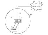
- FIG. 1 is a schematic diagram of a radio communication system according to an embodiment of the present invention.
- FIG. 2 is a configuration diagram of the radio base station shown in FIG. 1 in Embodiment 1. It is a block diagram of the wake-up signal receiver shown in FIG. It is a block diagram in Embodiment 1 of the terminal device shown in FIG. It is a figure which shows the conversion table of the bit length and the frame length L which is the time length of a radio
- FIG. 4 is a state transition diagram of the ID identifier shown in FIG. 3 when the wake-up signal is composed of a plurality of radio frames.
- FIG. 4 is a state transition diagram of the ID identifier shown in FIG. 3 when the wake-up signal is composed of a plurality of radio frames.
- FIG. 4 is a specific configuration diagram of a bit determination device shown in FIG. 3.
- 3 is a flowchart in the first embodiment for explaining an operation in the wireless communication system shown in FIG. 1.
- FIG. 6 is a configuration diagram of the radio base station shown in FIG. 1 in Embodiment 2. It is a block diagram of the wake-up signal receiver shown in FIG. It is a block diagram in Embodiment 2 of the terminal device shown in FIG. It is a conceptual diagram which shows the transmission method of wakeup ID in the wakeup signal generation part and radio
- FIG. 1 is a schematic diagram of a radio communication system according to an embodiment of the present invention.
- a radio communication system 10 according to an embodiment of the present invention includes a radio base station 1 and a terminal device 2.
- the radio base station 1 has a communication range REG.
- the radio base station 1 is connected to the network 30 via the wired cable 20.
- the wireless base station 1 is activated when it does not perform wireless communication with the terminal device 2 for a certain period of time or when there is no terminal device belonging to itself (that is, when there is no terminal device within the communication range REG). Transition from state to sleep state.
- the radio base station 1 when the radio base station 1 receives a wake-up signal for activating itself from the terminal device 2 in the sleep state, the radio base station 1 shifts from the sleep state to the activation state.
- the wireless base station 1 performs wireless communication with the terminal device 2 and also communicates with other communication devices via the wired cable 20 and the network 30. In this case, the radio base station 1 performs radio communication with the terminal device 2 in the 2.45 GHz band, for example.
- the terminal device 2 exists within the communication range REG of the radio base station 1.
- the terminal device 2 determines that the radio base station 1 is in the sleep state. Then, the terminal device 2 generates a wake-up signal for activating the wireless base station 1 when starting wireless communication with the wireless base station 1 when the wireless base station 1 is in the sleep state, The generated wakeup signal is transmitted to the radio base station 1 by radio communication in the 2.45 GHz band. That is, the terminal device 2 transmits a wake-up signal to the radio base station 1 using the same frequency band as that used for radio communication with the radio base station 1.
- the terminal device 2 performs normal wireless communication with the wireless base station 1 in the 2.45 GHz band when the wireless base station 1 is in the activated state.
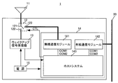
- FIG. 2 is a configuration diagram of the radio base station 1 shown in FIG. 1 in the first embodiment.
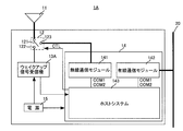
- radio base station 1 includes an antenna 11, a switch 12, a wake-up signal receiver 13, a main device 14, and a power supply 15.
- the antenna 11 is connected to the wake-up signal receiver 13 or the main device 14 via the switch 12.
- the switch 12 is connected between the antenna 11 and the wake-up signal receiver 13 and the main device 14.
- the antenna 11 receives a wireless frame from the terminal device 2 by wireless communication, and outputs the received wireless frame to the wakeup signal receiver 13 or the main device 14 via the switch 12. Further, the antenna 11 transmits the radio frame received from the main device 14 to the terminal device 2 by radio communication.
- the switch 12 connects the antenna 11 to the wake-up signal receiver 13 or the main device 14 according to the control signal CTL from the main device 14.
- the wake-up signal receiver 13 receives, for example, 100 ⁇ W of power from the power supply 15 and is driven by the received power.
- the wakeup signal receiver 13 is connected to the antenna 11 via the switch 12 when the main device 14 is in the sleep state. Then, when receiving a radio frame from the terminal device 2 via the antenna 11, the wake-up signal receiver 13 detects a wake-up ID represented by the length of the received radio frame, and the detected wake-up ID. Determines whether the ID matches the ID of the radio base station 1 or not.
- the wakeup signal receiver 13 determines that the wakeup ID matches the ID of the radio base station 1, the wakeup signal receiver 13 generates an activation signal and outputs the generated activation signal to the main device 14.
- the wakeup signal receiver 13 discards the radio frame. Then, the wakeup signal receiver 13 waits for reception of a radio frame.
- the wake-up signal receiver 13 has only a function of receiving a radio frame for wake-up of the radio base station 1, and does not have a function of transmitting a radio frame.
- the main device 14 receives, for example, 7 W of power from the power supply 15 and is driven by the received power.
- the main device 14 When the main device 14 is in the activated state, the main device 14 performs wireless communication with the terminal device 2 via the antenna 11 and communicates with other communication devices via the wired cable 20.
- the main device 14 shifts from the activated state to the sleep state when the wireless communication with the terminal device 2 is not performed for a certain period T1, or when there is no terminal device belonging to the wireless base station 1.
- the certain period T1 is set to several tens of seconds, for example.
- the main device 14 when the main device 14 is in the sleep state and receives an activation signal from the wake-up signal receiver 13, it shifts from the sleep state to the activation state.
- the power supply 15 supplies 100 ⁇ W of power to the wake-up signal receiver 13 and supplies 7 W of power to the main device 14.
- the switch 12 includes a switch 121 and terminals 122 and 123.
- the main device 14 includes a wireless communication module 141, a wired communication module 142, and a host system 143.
- the switch 121 is connected to the antenna 11.
- the terminal 122 is connected to the wakeup signal receiver 13.
- the terminal 123 is connected to the wireless communication module 141.
- the switch 121 receives a control signal CTL from the host system 143 of the main device 14.
- the switch 121 connects the antenna 11 to the terminal 122 or the terminal 123 by the control signal CTL.
- control signal CTL is composed of an L (logic low) level signal or an H (logic high) level signal.
- the switch 121 connects the antenna 11 to the terminal 122 when the control signal CTL is an L level signal, and connects the antenna 11 to the terminal 123 when the control signal CTL is an H level signal.
- the wireless communication module 141 When the wireless communication module 141 receives the command signal COM1 from the host system 143, the wireless communication module 141 shifts from the activated state to the sleep state, and upon receiving the command signal COM2 from the host system 143, the wireless communication module 141 shifts from the sleep state to the activated state.
- This sleep state is a state in which the wireless communication module 141 has stopped operating.
- the wireless communication module 141 shifts to the activated state, the wireless communication module 141 generates a wireless frame (activation notification) for notifying the terminal device 2 that the wireless base station 1 is activated, and the generated wireless frame (activation notification). Is transmitted to the terminal device 2.
- the wireless communication module 141 periodically transmits a beacon frame Beacon via the antenna 11 to establish a wireless communication link with the terminal device 2.
- the wireless communication module 141 performs wireless communication with the terminal device 2.
- the wireless communication module 141 extracts data from the wireless frame received from the terminal device 2, outputs the data to the host system 143, generates a wireless frame including the data received from the host system 143, and transmits the wireless frame to the terminal device 2. .
- the wired communication module 142 receives data from another communication device via the wired cable 20 and outputs the received data to the host system 143.
- the wired communication module 142 receives data from the host system 143 and transmits the received data to another communication device via the wired cable 20.
- the wired communication module 142 when the wired communication module 142 receives the command signal COM1 from the host system 143, the wired communication module 142 shifts from the activated state to the sleep state, and upon receiving the command signal COM2 from the host system 143, the wired communication module 142 shifts from the sleep state to the activated state.
- This sleep state is a state in which the wired communication module 142 has stopped operating.
- the host system 143 When the host system 143 does not receive the radio frame from the terminal device 2 via the radio communication module 141 for a certain period T1, or when the terminal device does not exist within the communication range REG, the host system 143 generates the command signal COM1.
- the host system 143 when the host system 143 receives the activation signal from the wakeup signal receiver 13, the host system 143 shifts from the sleep state to the activation state. Then, the host system 143 generates a command signal COM2, outputs the generated command signal COM2 to the wireless communication module 141 and the wired communication module 142, generates an H level control signal CTL, and outputs it to the switcher 12. To do.
- the host system 143 when receiving data from the wireless communication module 141, the host system 143 outputs the received data to the wired communication module 142.
- the host system 143 when receiving data from the wired communication module 142, the host system 143 outputs the received data to the wireless communication module 141.
- the host system 143 manages terminal devices that exist within the communication range REG.
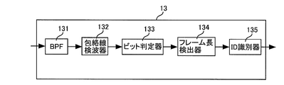
- FIG. 3 is a block diagram of the wake-up signal receiver 13 shown in FIG.
- wake-up signal receiver 13 includes BPF (Band Pass Filter) 131, envelope detector 132, bit determiner 133, frame length detector 134, and ID identifier 135. Including.
- BPF Band Pass Filter
- the BPF 131 receives a radio wave via the antenna 11 and the switch 12, and extracts a signal having a radio frame frequency from the received radio wave. Then, the BPF 131 outputs the extracted signal to the envelope detector 132.
- the envelope detector 132 detects the envelope of the radio frame received from the BPF 131 at regular intervals (for example, 10 ⁇ s), and outputs the detected detection signal to the bit determiner 133.
- the bit determination unit 133 converts the detection signal received from the envelope detector 132 into a bit value of “0” or “1”, and outputs the converted bit string to the frame length detector 134.
- the frame length detector 134 detects the frame length of the radio frame based on the bit string received from the bit determiner 133. More specifically, the frame length detector 134 accumulates the number of bit values “1”, and when a bit value “0” is input, outputs the accumulated value to the ID identifier 135 and Reset the value.
- the ID identifier 135 receives the accumulated value from the frame length detector 134 and converts the received accumulated value into a bit string by a method described later. Then, the ID identifier 135 holds the converted bit string.
- the ID identifier 135 generates an activation signal and outputs it to the host system 143 when the held bit string matches the identification information (ID) of the radio base station 1.
- the ID identifier 135 discards the bit string in order from the oldest bit value.
- FIG. 4 is a configuration diagram of the terminal device 2 shown in FIG. 1 in the first embodiment.
- the terminal device 2 includes an antenna 21, a wireless communication module 22, and a host system 23.
- the host system 23 includes a wakeup signal generation unit 231.
- the wireless communication module 22 When the wireless communication module 22 receives the activation notification from the wireless base station 1 via the antenna 21, the wireless communication module 22 establishes a wireless communication link with the wireless base station 1 and performs wireless communication with the wireless base station 1.
- the radio communication module 22 receives a radio frame from the radio base station 1 via the antenna 21, demodulates the received radio frame, extracts data, and outputs the extracted data to the host system 23.
- the wireless communication module 22 receives data from the host system 23, generates a wireless frame including the received data, modulates the generated wireless frame by a modulation method using a wireless LAN, and transmits the modulated wireless frame to the antenna.
- the data is transmitted to the radio base station 1 via 21.
- the wireless communication module 22 transmits the payload received from the wakeup signal generation unit 231 of the host system 23 to the wireless base station 1 via the antenna 21 at the transmission rate similarly received from the wakeup signal generation unit 231.
- the host system 23 receives the beacon frame Beacon received by the wireless communication module 22 via the antenna 21 from the wireless communication module 22. Then, the host system 23 extracts and manages the ESSID or BSSID included in the received beacon frame Beacon, and manages the radio base station 1 to which the terminal device 2 belongs based on the ESSID or BSSID.
- the host system 23 determines that the radio base station 1 is in the sleep state, and sends the command signal COM 3 and ESSID (or BSSID) to the wake-up signal generation unit 231. Output.
- the host system 23 receives data from the wireless communication module 22, generates data, and outputs the data to the wireless communication module 22.
- the wakeup signal generation unit 231 When the wakeup signal generation unit 231 receives the command signal COM3 and ESSID (or BSSID) from the host system 23, the wakeup signal generation unit 231 generates a wakeup ID including any one of ESSID, BSSID, and hash values thereof, and the generated wakeup signal
- the up ID and the transmission rate for transmitting the radio frame such that the time length of the transmitted radio frame becomes the wake-up ID are output to the radio communication module 22.
- the wakeup ID is information indicating a radio base station that is activated by the terminal device 2.
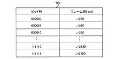
- FIG. 5 is a diagram showing a conversion table between a bit string and a frame length L that is a time length of a radio frame.
- conversion table TBL1 includes a bit string and a frame length. The bit string and the frame length are associated with each other.
- the frame length L of 230 ⁇ s is associated with the bit string “000000”.
- the frame length L of 260 ( ⁇ s) is associated with the bit string “000001”.
- the frame length L of 290 ( ⁇ s) is associated with the bit string “000010”.
- the frame length L of 2120 ( ⁇ s) is associated with the bit string “111110”
- the frame length L of 2150 ( ⁇ s) is associated with the bit string “111111”.
- a bit string such as “000000” is a wakeup ID. That is, a bit string such as “000000” is identification information of the radio base station 1 to be woken up.
- the wake-up signal generation unit 231 holds a conversion table TBL1.
- the wireless communication module 22 receives the payload from the wake-up signal generation unit 231, generates a wireless frame including the received payload, and transmits the generated wireless frame to the wireless base station 1.
- the wakeup signal generation unit 231 sets the time length of the radio frame including the wakeup ID consisting of “000000” to 230 ( ⁇ s). ) Is determined, and the determined transmission rate and the wake-up ID including 000000 ′′ are output to the wireless communication module 22.
- the wireless communication module 22 wakes up including 000000 ′′.
- the ID and the transmission rate are received from the wakeup signal generation unit 231.
- the radio communication module 22 generates a radio frame including a wake-up ID consisting of 000000 ′′, and transmits the generated radio frame to the radio base station 1 at the transmission rate received from the wake-up signal generation unit 231.
- the wireless communication module 22 receives the payload and transmission rate from the wake-up signal generation unit 231 and generates a wireless frame including the received payload. Then, the wireless communication module 22 receives the generated wireless frame from the wakeup signal generation unit 231 and transmits it to the wireless base station 1 at a transmission rate.
- the frame is transmitted to the radio base station 1.
- the terminal device 2 can wake up the radio base station 1 only by adding the wakeup signal generation unit 231 without changing the radio communication module 22.
- the content of the data serving as the payload may be a random value or a specific value.
- the wakeup signal generation unit 231 outputs the payload and / or transmission rate to the wireless communication module 22 in the same manner for the wakeup ID composed of “000001” and the like.
- the frame length L is divided every 30 ⁇ s because the clock frequency of the wakeup signal receiver 13 of the radio base station 1 is lowered, and the wakeup signal receiver 13 identifies the break of the radio frame. This is to make it possible.
- the terminal device 2 transmits to the radio base station 1 a radio frame in which the wakeup ID is represented by the frame length.
- the radio frame is transmitted from a management frame such as Probe Request, a broadcast data frame, or a data frame to be transmitted to a radio base station other than the radio base station 1 to be woken up or a terminal device other than the terminal device 2.
- a management frame such as Probe Request, a broadcast data frame, or a data frame to be transmitted to a radio base station other than the radio base station 1 to be woken up or a terminal device other than the terminal device 2.
- the wake-up signal generation unit 231 adjusts the transmission rate and fragmentation of the data frame, and transmits the radio frame having the frame length L corresponding to the wake-up ID to the radio communication module 22 and the antenna 21. To the wireless base station 1.
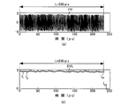
- FIG. 6 is a conceptual diagram of envelope detection and bit determination.
- envelope detector 132 of wakeup signal receiver 13 receives radio frame FR from BPF 131.
- the radio frame FR has a frame length L of 230 ( ⁇ s), for example (see (a)).
- the envelope detector 132 detects the envelope EVL of the radio frame FR, detects the detected envelope EVL every 10 ( ⁇ s), and detects the detected values I 1 to I 24 (see (b)). .
- envelope detector 132 outputs detection values I 1 to I 24 to bit determination unit 133.
- the bit determiner 133 performs bit determination on the detection values I 1 to I 24 to obtain a bit string “111... 1110”. Then, the bit determining unit 133 outputs a bit string “111... 1110” to the frame length detector 134.
- the frame length detector 134 accumulates the number of bit values “1” from the beginning of the bit string “111... 1110” and detects the accumulated value “23”. Since the 24th bit value is “0”, the frame length detector 134 outputs the accumulated value of “23” to the ID identifier 135 and resets the accumulated value.
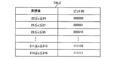
- FIG. 7 is a diagram showing a conversion table between cumulative values and bit strings.
- conversion table TBL2 includes cumulative values and bit strings. The accumulated value and the bit string are associated with each other.
- the bit string “000000” is associated with the accumulated value c of 22 ⁇ c ⁇ 24.
- the bit string “000001” is associated with the accumulated value c of 25 ⁇ c ⁇ 27.
- the bit string “000010” is associated with the accumulated value c of 28 ⁇ c ⁇ 30.
- the bit string “111110” is associated with the accumulated value c of 211 ⁇ c ⁇ 213, and the bit string “111111” is associated with the accumulated value of 214 ⁇ c ⁇ 216.
- the ID identifier 135 holds a conversion table TBL2.
- the ID identifier 135 receives the accumulated value c of 23 from the frame length detector 134, the ID identifier 135 refers to the conversion table TBL2 to detect the bit string “000000”.
- the ID identifier 135 generates an activation signal and outputs it to the main device 14.
- FIG. 8 is a state transition diagram of the ID identifier 135 shown in FIG. 3 when the wake-up signal is composed of a plurality of radio frames.
- the terminal device 2 may transmit a wake-up signal to the radio base station 1 using a plurality of radio frames.
- the wakeup signal receiver 13 cannot correctly decode the wakeup signal when a radio frame transmitted from a terminal device other than the terminal device 2 interrupts a radio frame transmitted from the terminal device 2.
- the ID identifier 135 has the configuration shown in FIG. That, ID identifier 135, c 1 wait state 1351, c 2 wait state 1352, ..., (the n 2 or more integer) c n wait state 135n having.
- the ID identifier 135 When the radio base station 1 enters the sleep state, the ID identifier 135 is initially in the c 1 waiting state 1351, and the accumulated values c 1 or accumulated values close to c 1 , for example, c 1 ⁇ 1 and c 1 +1 are when receiving, the process proceeds to c 2 wait state 1352. If the cumulative value c 2 or the cumulative value close to c 2 is input, the ID identifier 135 proceeds to the c 3 waiting state 1353.
- ID identifier 135 if it is the accumulated value close to the accumulated value c n-1 or c n-1 is input, the process proceeds to c n waiting 135N, the cumulative value c n or c n If a close cumulative value is input, it is determined that the identification information (ID) is matched, and an activation signal is generated and output to the main device 14. As a result, the radio base station 1 shifts to an activated state.
- the ID identifier 135 wakes up by detecting n accumulated values c 1 , c 2 ,..., C n. ID is detected.
- the ID identifier 135 continuously receives n accumulated values c 1 , c 2 ,..., C n even if a wireless frame that is not a wake-up signal coincides with the accumulated value that happens to be waiting. if not, return to the c 1 wait state 1351 is the initial state.
- During transmission terminal apparatus 2 is a wake-up signal, if interrupted by a radio frame of another terminal apparatus, ID identifier 135, for example, in c 2 wait state 1352, the accumulated value c 2 or cumulative values close to c 2 state be different accumulated value input, wait for the c once the accumulated value of 2 is inputted, the cumulative value c 3 a state following before a certain period, or m times more different cumulative values are input Transition to.
- the wakeup signal can be correctly received even when the wakeup signal is transmitted using a plurality of radio frames, and the main device 14 can be activated.
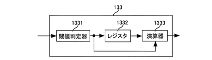
- FIG. 9 is a specific configuration diagram of the bit determination unit 133 shown in FIG. Referring to FIG. 9, bit determiner 133 includes a threshold determiner 1331, a register 1332, and a calculator 1333.
- the threshold value determiner 1331 holds in advance a threshold value RSSI_th1 of ⁇ 90 dBm, for example. Then, the threshold determination unit 1331, bit determines detection value I 1 ⁇ I 24 a detection value I 1 ⁇ I 24 received from envelope detector 132 is compared with a threshold value RSSI_th1. That is, the threshold value determiner 1331 converts the detection values I 1 to I 24 to “1” if the detection values I 1 to I 24 are greater than or equal to the threshold RSSI_th1, and the detection values I 1 to I 24 are greater than the threshold RSSI_th1. If low, the detection values I 1 to I 24 are converted to “0”.
- the threshold determination unit 1331 outputs a bit string composed of the converted bit value to the register 1332 and the arithmetic unit 1333.
- the register 1332 holds the bit string received from the threshold determination unit 1331 while shifting the bit string by one bit every cycle, and sequentially outputs the held bit string to the arithmetic unit 1333.
- the calculator 1333 sequentially receives each bit value of the bit string from the threshold value determiner 1331 and sequentially receives each bit value delayed by one cycle from the register 1332. Then, the calculator 1333 calculates a logical sum (OR) of the received two bit values and outputs the calculation result to the frame length detector 134.
- the space between frames in IEEE 802.11b is 30 ⁇ s or more. Then, the envelope detector 132 performs envelope detection every 10 ⁇ s, and the bit determination unit 133 performs bit determination every 10 ⁇ s. Accordingly, there are always two or more “0” s between radio frames. For this reason, if the result of bit determination is “101”, “0” has a high probability of being an error.
- bit determination unit 133 since the bit determination unit 133 has the configuration shown in FIG. 9, the bit string “101” is corrected to “111”. Therefore, the bit determination unit 133 can perform bit determination by reducing the bit error by adopting the configuration shown in FIG.
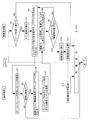
- FIG. 10 is a flowchart in the first embodiment for explaining the operation in the radio communication system 10 shown in FIG.
- the host system 143 of the radio base station 1 determines whether or not to shift to the sleep state (step S1). More specifically, the host system 143 of the radio base station 1 is not performing radio communication with the terminal device 2 for a certain period T1, or there is no terminal device belonging to the radio base station 1. Or when there is a determination by some other determination algorithm such as scheduling, it is determined to shift to the sleep state. In addition, the host system 143 of the radio base station 1 performs radio communication with the terminal device 2 within a certain period T1, or when a terminal device belonging to the radio base station 1 exists. It determines with not shifting to a sleep state.
- step S1 when it is determined to shift to the sleep state, the host system 143 of the wireless base station 1 generates a command signal COM1 and outputs it to the wireless communication module 141 and the wired communication module 142, and from the L level signal.
- the control signal CTL is generated and output to the switch 12 to stop its own operation.
- the switch 12 of the radio base station 1 connects the antenna 11 to the terminal 122 according to the L level control signal CTL.
- the wireless communication module 141 and the wired communication module 142 of the wireless base station 1 stop operating in response to the command signal COM1. That is, when it is determined in step S1 that the sleep state is to be entered, the main device 14 is stopped (step S2).
- the wakeup signal receiver 13 waits for a wakeup signal (step S3).
- the host system 23 of the terminal device 2 detects that the beacon frame Beacon is not received from the radio base station 1 (step S4). That is, the host system 23 of the terminal device 2 detects that the wireless base station 1 is in the sleep state. Then, the host system 23 of the terminal device 2 determines whether or not to start wireless communication (step S5).
- the host system 23 of the terminal device 2 When it is determined in step S5 that wireless communication is to be started, the host system 23 of the terminal device 2 outputs the ESSID (or BSSID) of the wireless base station 1 to be activated and the command signal COM3 to the wakeup signal generation unit 231. To do.
- the wakeup signal generation unit 231 of the terminal device 2 receives the command signal COM3, the wakeup signal generation unit 231 generates a wakeup ID by the above-described method based on the ESSID (or BSSID). That is, the terminal device 2 generates a wakeup ID indicating the radio base station 1 to be activated (step S6).
- the wakeup signal generation unit 231 of the terminal device 2 calculates a payload size and a transmission rate necessary for representing the generated wakeup ID by a radio frame length, and generates a payload having the calculated payload size. Then, the generated payload and the calculated transmission rate are output to the wireless communication module 22.
- the radio communication module 22 of the terminal device 2 converts the payload received from the wakeup signal generation unit 231 into a radio frame having a transmission rate received from the wakeup signal generation unit 231, and the converted radio frame is transmitted via the antenna 21. Transmit to the radio base station 1 (step S7). More specifically, the wakeup signal generation unit 231 of the terminal device 2 determines at least one of the payload size and the transmission rate so that the frame length represents the wakeup ID, and at least the determined payload size and transmission rate. One is used to transmit a radio frame to the radio base station 1.
- the wakeup signal receiver 13 of the radio base station 1 receives the radio frame via the antenna 11, and detects the wakeup ID from the frame length of the received radio frame by the method described above (step S8).
- the wakeup signal receiver 13 of the radio base station 1 determines whether or not the detected wakeup ID matches the ID of the radio base station 1 (step S9).
- step S9 When it is determined in step S9 that the wakeup ID does not match the ID of the radio base station 1, the series of operations returns to step S3.
- step S9 when it is determined in step S9 that the wakeup ID matches the ID of the radio base station 1, the wakeup signal receiver 13 of the radio base station 1 generates an activation signal and outputs it to the host system 143. Then, the host system 143 of the wireless base station 1 shifts from the sleep state to the activated state in response to the activation signal from the wakeup signal receiver 13, generates the command signal COM2, and generates the wireless communication module 141 and the wired communication module 142. Output to. Then, the wireless communication module 141 and the wired communication module 142 of the wireless base station 1 shift from the sleep state to the activated state according to the command COM2. As described above, the main device 14 of the radio base station 1 shifts from the sleep state to the activated state in accordance with the activation signal from the wakeup signal receiver 13 (step S10).
- the wireless communication module 141 of the wireless base station 1 generates an activation notification, and transmits the generated activation notification to the terminal device 2 via the antenna 11 (step S11).
- the wireless communication module 22 of the terminal device 2 receives the activation notification via the antenna 21 (step S12), and outputs the received activation notification to the host system 23. Thereafter, the host system 23 of the terminal device 2 detects that the wireless base station 1 has shifted from the sleep state to the activated state in response to the activation notification from the wireless communication module 22.
- the wireless communication module 141 of the wireless base station 1 starts wireless communication for establishing a wireless communication link with the terminal device 2, establishes a wireless communication link with the terminal device 2, and performs wireless communication. Is performed (step S13).
- Step S1 when it is determined not to shift to the sleep state, the series of operations proceeds to Step S13.
- step S13 after step S13 or when it is determined in step S5 that the wireless communication is not started, the series of operations ends.
- the wakeup signal receiver 13 of the radio base station 1 detects the wakeup ID by the method described in FIG. 8 in step S8 when the wakeup ID is represented by a plurality of frame lengths of a plurality of radio frames. To do.
- the wakeup signal receiver 13 of the wireless base station 1 performs bit determination by the method described in FIG. 8 and detects a wakeup ID in step S8.
- the terminal device 2 transmits to the radio base station 1 a radio frame in which the ID of the radio base station 1 to be woken up is represented by the frame length. Then, the radio base station 1 detects the wakeup ID from the frame length of the radio frame from the terminal device 2, and shifts from the sleep state to the activated state when the detected wakeup ID matches its own ID.
- the radio frame is a radio frame in IEEE 802.11.
- the radio base station 1 can be activated using a radio frame in IEEE 802.11.
- the wakeup ID is transmitted from the terminal apparatus 2 to the radio base station 1 using a normal radio frame and received by the radio base station 1, so that the radio base station 1 and the terminal apparatus 2 set the wakeup ID.
- the number of antennas can be reduced to one.
- FIG. 11 is a configuration diagram of the radio base station 1 shown in FIG. 1 in the second embodiment.
- the radio base station 1 shown in FIG. 1 includes the radio base station 1A shown in FIG.
- radio base station 1A is obtained by replacing wake-up signal receiver 13 of radio base station 1 shown in FIG. 2 with wake-up signal receiver 13A. Same as 1.
- the wakeup signal receiver 13A receives a radio wave via the antenna 11 and detects a wakeup ID based on the amplitude of the received radio wave. Then, when the detected wakeup ID matches the identification information (ID) of the radio base station 1A, the wakeup signal receiver 13A generates an activation signal and outputs it to the main device 14.
- ID identification information
- the wakeup signal receiver 13A discards the wakeup ID.
- FIG. 12 is a block diagram of the wake-up signal receiver 13A shown in FIG.
- wakeup signal receiver 13A replaces bit determination unit 133 of wakeup signal receiver 13 shown in FIG. 3 with bit determination unit 133A, and replaces frame length detector 134 with amplitude detector 136.
- the ID discriminator 135 is replaced with an ID discriminator 135A, and the other parts are the same as those of the wake-up signal receiver 13.
- the amplitude detector 136 is disposed between the envelope detector 132 and the bit determiner 133A, and the bit determiner 133A outputs the bit determination result to the ID identifier 135A. .
- the amplitude detector 136 holds in advance a threshold RSSI_th2 of, for example, ⁇ 80 dBm.
- the amplitude IP n is detected by averaging the detected values I 1 to In n .
- the bit determination unit 133A holds a threshold RSSI_th3 in advance.
- the threshold RSSI_th3 is, for example, 10 dB.
- Bit determiner 133A receives amplitude IP n from amplitude detector 136. Then, the bit determination unit 133A calculates the absolute value ⁇ IP n of the difference between the amplitude IP n ⁇ 1 and the amplitude IP n, and if the calculated absolute value ⁇ IP n is equal to or less than the threshold value RSSI_th3, ID “0” is identified. If the absolute value ⁇ IP n is larger than the threshold RSSI_th3, “1” is output to the ID discriminator 135A.
- the ID identifier 135A holds the bit string received from the bit determiner 133A as a bit string in the order of input, and generates an activation signal when the held bit string matches the identification information (ID) of the radio base station 1A. Output to the main device 14. On the other hand, when the number of bits of the held bit string exceeds the number of bits of the wakeup ID, the ID identifier 135A discards the bits in the order of input.
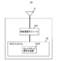
- FIG. 13 is a configuration diagram of the terminal device 2 shown in FIG. 1 in the second embodiment.
- the terminal device 2 shown in FIG. 1 includes the terminal device 2A shown in FIG.
- terminal device 2A is obtained by replacing radio communication module 22 of terminal device 2 shown in FIG. 4 with radio communication module 22A and replacing wakeup signal generation unit 231 with wakeup signal generation unit 231A.
- the other parts are the same as those of the terminal device 2.
- the wakeup signal generation unit 231A generates a fixed-length payload and sets transmission power so that the radio frame represents a wakeup ID. Then, wakeup signal generation section 231A outputs the generated payload and the set transmission power information to radio communication module 22A.
- the radio communication module 22A generates a radio frame including the payload received from the wakeup signal generation unit 231A, and transmits the generated radio frame to the radio base station via the antenna 21 with the transmission power received from the wakeup signal generation unit 231A. Send to 1A.
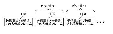
- FIG. 14 is a conceptual diagram showing a wakeup ID transmission method in wakeup signal generation section 231A and wireless communication module 22A shown in FIG.
- wakeup signal generation section 231A first generates a fixed-length payload, sets transmission power X in the generated payload, and outputs it to radio communication module 22A. Then, the radio communication module 22A generates a radio frame FR1 including the payload received from the wakeup signal generation unit 231A, and transmits the generated radio frame FR1 through the antenna 21 with the transmission power X. After that, if the first bit value of the wakeup ID is “0”, the wakeup signal generation unit 231A sets the transmission power X again in the newly generated payload and outputs it to the wireless communication module 22A.
- the radio communication module 22A generates a radio frame FR2 including the payload received from the wakeup signal generation unit 231A, and transmits the generated radio frame FR2 through the antenna 21 with the transmission power X.
- the wakeup signal generation unit 231A sets the transmission power Y different from the transmission power X in the newly generated payload and outputs it to the wireless communication module 22A. To do.
- the radio communication module 22A generates a radio frame FR3 including the payload received from the wakeup signal generation unit 231A, and transmits the generated radio frame FR3 via the antenna 21 with the transmission power Y.
- the wakeup signal generation unit 231A outputs the same transmission power as the transmission power set immediately before to the wireless communication module 22A together with the newly generated payload. . If the bit value is “1”, the wakeup signal generation unit 231A outputs transmission power different from the transmission power set immediately before to the wireless communication module 22A together with the newly generated payload. Then, the wireless communication module 22A generates a radio frame including the payload received from the wakeup signal generation unit 231A, and transmits the generated radio frame with the transmission power received from the wakeup signal generation unit 231A.
- the wakeup signal generation unit 231A transmits a radio frame whose amplitude represents the wakeup ID via the radio communication module 22A by assigning each bit of the wakeup ID to the transmission power.
- the bit determination unit 133A outputs “0” to the ID discriminator 135A, and the absolute value If ⁇ IP n is larger than threshold RSSI_th3, “1” is output to ID identifier 135A.
- the transmission method of each bit value of the wakeup ID in the wakeup signal generation unit 231A matches the bit determination method in the bit determination unit 133A.
- the bit determination unit 133A the output amplitude IP n, if the absolute value Delta] Ip n of the difference between the amplitude IP n-1 immediately preceding amplitude IP n threshold RSSI_th3 less, the bit value of "0" To do.
- This corresponds to transmitting a radio frame indicating a bit value of “0” with the transmission power used for transmitting the radio frame transmitted immediately before in the wakeup signal generation unit 231A and the radio communication module 22A. .
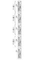
- FIG. 15 is a diagram illustrating a specific example of a wakeup ID transmission method in the wakeup signal generation unit 231A illustrated in FIG.
- radio communication module 22A when a wakeup ID consisting of a bit string “0101” is transmitted, radio communication module 22A first transmits radio frame FR1 with transmission power X, and then sets a bit value of “0”.
- the radio frame FR2 is transmitted with the transmission power X as it is, the radio frame FR3 indicating the bit value of “1” is transmitted with the transmission power Y different from the transmission power X, and the radio frame FR4 indicating the bit value of “0” is transmitted. Transmission is performed with the transmission power Y as it is, and a radio frame FR5 indicating a bit value of “1” is transmitted with a transmission power X different from the transmission power Y.
- the bit value “0” may be transmitted with the transmission power X or may be transmitted with the transmission power Y (see the radio frames FR2 and FR4).
- the bit value of “1” may be transmitted with the transmission power Y or may be transmitted with the transmission power X (see the radio frames FR3 and FR5).
- the transmission power X, Y is such that the difference between the transmission power X and the transmission power Y is greater than the threshold RSSI_th3 so that each bit value of the bit string “0101” is accurately determined by the bit determination unit 133A. It is determined to be larger.
- FIG. 16 is a flowchart in the second embodiment for explaining the operation in the wireless communication system 10 shown in FIG.
- FIG. 16 is the same as the flowchart shown in FIG. 10 except that steps S7 and S8 in the flowchart shown in FIG. 10 are replaced with steps S7A and S8A, respectively.
- steps S1 to S6 described above are sequentially executed. Then, after step S6, the wakeup signal generation unit 231A and the radio communication module 22A of the terminal device 2A transmit a radio frame having an amplitude indicating the wakeup ID via the antenna 21 by the method described above (step S7A). ).
- the wakeup signal receiver 13A of the radio base station 1A receives the radio frame via the antenna 11, and detects the wakeup ID from the amplitude of the received radio frame by the method described above (step S8A).
- steps S9 to S13 are sequentially executed. And when it determines with not starting communication in step S5, or after step S13, a series of operation
- the terminal device 2A transmits to the radio base station 1A a radio frame in which the ID of the radio base station 1A to be woken up is expressed in amplitude. Then, the radio base station 1A detects the wakeup ID from the amplitude of the radio frame from the terminal device 2A, and when the detected wakeup ID matches its own ID, the radio base station 1A shifts from the sleep state to the activated state.
- the radio frame is a radio frame in IEEE 802.11.
- the radio base station 1A can be activated using a radio frame in IEEE 802.11.
- the wakeup ID is transmitted from the terminal device 2A to the radio base station 1A using a normal radio frame and received by the radio base station 1A. Therefore, the radio base station 1A and the terminal device 2A set the wakeup ID. There is no need for a special device for transmitting and receiving, and the number of antennas can be reduced to one.
- a radio frame representing a wake-up ID by a frame length is transmitted from the terminal device 2 to the radio base station 1, and the radio base station 1 is shifted from the sleep state to the activated state.
- the radio frame representing the wake-up ID by amplitude is transmitted from the terminal device 2A to the radio base station 1A, and the radio base station 1A is shifted from the sleep state to the activated state.
- the wireless communication system includes a terminal device that transmits a wireless frame that represents a wake-up ID by a frame length or amplitude to the wireless base station 1 (or 1A), and a wireless frame received from the terminal device. And a radio base station that shifts from a sleep state to an activated state when the detected wakeup ID matches its own identification information (ID). .
- ID own identification information
- the wireless communication module 22 and the wake-up signal generation unit 231 of the terminal device 2 constitute a “wireless module”.
- the wireless communication module 22A and the wake-up signal generation unit 231A of the terminal device 2A constitute a “wireless module”.
- the present invention is applied to a terminal device, a radio base station that performs radio communication with the terminal device, and a radio communication system using them.
Landscapes
- Engineering & Computer Science (AREA)
- Computer Networks & Wireless Communication (AREA)
- Signal Processing (AREA)
- Mobile Radio Communication Systems (AREA)
Abstract
Selon l'invention, un dispositif terminal (2) transmet une trame sans fil à une station de base sans fil (1), ladite trame sans fil indiquant l'identificateur de la station de base sans fil (1) devant être réveillée au moyen de la longueur ou de l'amplitude de la trame. Ensuite, la station de base sans fil (1) détecte l'identificateur de réveil à partir de la longueur ou de l'amplitude de la trame provenant du dispositif terminal (2), et lorsque l'identificateur de réveil détecté est identique à l'identificateur de la station de base sans fil (1), la station de base sans fil (1) effectue une transition d'un mode sommeil à un mode de démarrage. Dans cette situation, la trame sans fil est la même que des trames sans fil envoyées et reçues entre un module de communication sans fil du dispositif terminal (2) et la station de base sans fil (1).
Priority Applications (1)
| Application Number | Priority Date | Filing Date | Title |
|---|---|---|---|
| US14/001,060 US9374784B2 (en) | 2011-02-23 | 2012-02-16 | Terminal device, wireless base station wirelessly communicating with the same, and wireless communication system using terminal device and wireless base station |
Applications Claiming Priority (2)
| Application Number | Priority Date | Filing Date | Title |
|---|---|---|---|
| JP2011-037306 | 2011-02-23 | ||
| JP2011037306A JP5190569B2 (ja) | 2011-02-23 | 2011-02-23 | 端末装置、それと無線通信を行う無線基地局およびそれらを用いた無線通信システム |
Publications (1)
| Publication Number | Publication Date |
|---|---|
| WO2012114969A1 true WO2012114969A1 (fr) | 2012-08-30 |
Family
ID=46720751
Family Applications (1)
| Application Number | Title | Priority Date | Filing Date |
|---|---|---|---|
| PCT/JP2012/053612 Ceased WO2012114969A1 (fr) | 2011-02-23 | 2012-02-16 | Dispositif terminal, station de base sans fil communiquant sans fil avec celui-ci, et système de communication sans fil utilisant un dispositif terminal et une station de base sans fil |
Country Status (3)
| Country | Link |
|---|---|
| US (1) | US9374784B2 (fr) |
| JP (1) | JP5190569B2 (fr) |
| WO (1) | WO2012114969A1 (fr) |
Cited By (4)
| Publication number | Priority date | Publication date | Assignee | Title |
|---|---|---|---|---|
| EP2838294A1 (fr) * | 2013-08-16 | 2015-02-18 | Alcatel Lucent | Émetteur-récepteur, noeud de réseau, système de télécommunication et procédé de communication |
| EP2785113A4 (fr) * | 2013-02-04 | 2015-07-22 | Huawei Device Co Ltd | Procédé et appareil permettant de réveiller un dispositif |
| CN105453653A (zh) * | 2013-08-07 | 2016-03-30 | Lg电子株式会社 | 在多无线接入技术环境中应用户设备的请求转变网络节点的状态的方法及其设备 |
| JP2022508471A (ja) * | 2019-01-10 | 2022-01-19 | シグニファイ ホールディング ビー ヴィ | 低電力のリピータ動作モードで動作可能な信号リピータデバイス |
Families Citing this family (20)
| Publication number | Priority date | Publication date | Assignee | Title |
|---|---|---|---|---|
| JP5969399B2 (ja) * | 2013-01-10 | 2016-08-17 | Kddi株式会社 | ダミー識別子を利用した信号により通信を起動させる無線アクセスポイント、通信起動プログラム及び方法 |
| WO2014155762A1 (fr) * | 2013-03-25 | 2014-10-02 | 日本電気通信システム株式会社 | Programme exécuté dans un émetteur, récepteur, et programme exécuté dans le récepteur |
| JP6168624B2 (ja) * | 2013-11-13 | 2017-07-26 | 日本電気通信システム株式会社 | 基地局、無線端末、通信システム、通信方法、プログラム |
| PL2903206T3 (pl) * | 2014-01-29 | 2020-06-01 | Sercel | Sposób wybudzania urządzenia zdalnego z urządzenia lokalnego |
| MX391611B (es) | 2014-01-31 | 2025-03-11 | Mitsubishi Electric Corp | Sistema de comunicación, dispositivo terminal de comunicación y dispositivo de estación base. |
| JP6450905B2 (ja) * | 2014-07-16 | 2019-01-16 | 学校法人 関西大学 | 移動無線装置、それを備えた無線通信システムおよび移動無線装置において実行されるプログラム |
| JP6432725B2 (ja) * | 2014-07-16 | 2018-12-05 | 学校法人 関西大学 | 無線装置、それを備えた無線通信システムおよび無線装置において実行されるプログラム |
| CN104202221A (zh) * | 2014-08-19 | 2014-12-10 | 中兴通讯股份有限公司 | 一种唤醒家庭互联设备的方法和设备 |
| US9525540B1 (en) * | 2015-06-18 | 2016-12-20 | Qualcomm Incorporated | Embedded wake-up signaling |
| JP6391015B2 (ja) * | 2015-09-29 | 2018-09-19 | サイレックス・テクノロジー株式会社 | 無線中継装置 |
| CN109690574B (zh) * | 2016-08-11 | 2022-04-01 | 大唐移动通信设备有限公司 | 用于按需移动设备访问的方法和装置 |
| US10235852B2 (en) | 2016-08-29 | 2019-03-19 | A9.Com, Inc. | Wireless security network and communication methods |
| WO2018074766A1 (fr) * | 2016-10-20 | 2018-04-26 | 엘지전자 주식회사 | Procédé et appareil de transmission de paquet de réveil dans un système lan sans fil |
| CN108282847B (zh) * | 2017-01-05 | 2022-01-18 | 中兴通讯股份有限公司 | 一种唤醒方法、装置和系统 |
| US11064437B2 (en) | 2017-01-19 | 2021-07-13 | Nokia Technolgies Oy | Power saving for wireless device |
| US10115278B2 (en) | 2017-03-31 | 2018-10-30 | A9.Com, Inc. | Wireless security network and communication methods |
| US20180288699A1 (en) * | 2017-03-31 | 2018-10-04 | A9.Com, Inc. | Wireless security network and communication methods |
| US10624086B2 (en) | 2017-03-31 | 2020-04-14 | A9.Com, Inc. | Wireless security network and communication methods |
| US10652823B2 (en) * | 2017-06-07 | 2020-05-12 | Imec Vzw | Wakeup receiver |
| JP6638922B2 (ja) * | 2018-08-02 | 2020-02-05 | 学校法人 関西大学 | 無線装置、それを備えた無線通信システムおよび無線装置において実行されるプログラム |
Citations (5)
| Publication number | Priority date | Publication date | Assignee | Title |
|---|---|---|---|---|
| JP2006516374A (ja) * | 2003-01-16 | 2006-06-29 | ソムフィ ソシエテ パ アクシオンス シンプリフィエ | コマンド送信機とコマンド送受信機との間の通信方法 |
| JP2009510835A (ja) * | 2005-09-19 | 2009-03-12 | クゥアルコム・インコーポレイテッド | マルチモード基地局を使用する無線通信システムにおいて使用される方法および装置 |
| JP2009077375A (ja) * | 2007-08-24 | 2009-04-09 | Toshiba Corp | 無線通信装置,および無線通信システム |
| JP2009232103A (ja) * | 2008-03-21 | 2009-10-08 | Ntt Electornics Corp | 無線装置 |
| WO2010002991A1 (fr) * | 2008-07-02 | 2010-01-07 | Qualcomm Incorporated | Modes basse puissance pour cellules femto |
Family Cites Families (7)
| Publication number | Priority date | Publication date | Assignee | Title |
|---|---|---|---|---|
| US7269145B2 (en) * | 2001-12-20 | 2007-09-11 | Samsung Electronics Co., Ltd. | Mode transition method for wireless data service in a mobile station |
| US6980839B2 (en) | 2003-04-30 | 2005-12-27 | Sony Corporation | Apparatus, system and method for use in powering on a remote wireless device |
| US20070146157A1 (en) | 2004-01-09 | 2007-06-28 | Michel Ramus | Method for communicating between an order transmitter and an order receiver-transmitter |
| US20070253468A1 (en) | 2006-05-01 | 2007-11-01 | Micrel Inc. | Spread Spectrum ASK/OOK Transmitter |
| US8588118B2 (en) | 2007-08-24 | 2013-11-19 | Kabushiki Kaisha Toshiba | Wireless communication device and wireless communication system |
| KR101139223B1 (ko) * | 2008-12-15 | 2012-04-24 | 한국전자통신연구원 | 웨이크업 신호 통신장치 및 방법 |
| JP6390043B2 (ja) * | 2012-02-28 | 2018-09-19 | 株式会社国際電気通信基礎技術研究所 | 送信機、それにおける送信方法、送信機から無線信号を受信する受信機およびそれらを備える無線通信システム |
-
2011
- 2011-02-23 JP JP2011037306A patent/JP5190569B2/ja active Active
-
2012
- 2012-02-16 US US14/001,060 patent/US9374784B2/en active Active
- 2012-02-16 WO PCT/JP2012/053612 patent/WO2012114969A1/fr not_active Ceased
Patent Citations (5)
| Publication number | Priority date | Publication date | Assignee | Title |
|---|---|---|---|---|
| JP2006516374A (ja) * | 2003-01-16 | 2006-06-29 | ソムフィ ソシエテ パ アクシオンス シンプリフィエ | コマンド送信機とコマンド送受信機との間の通信方法 |
| JP2009510835A (ja) * | 2005-09-19 | 2009-03-12 | クゥアルコム・インコーポレイテッド | マルチモード基地局を使用する無線通信システムにおいて使用される方法および装置 |
| JP2009077375A (ja) * | 2007-08-24 | 2009-04-09 | Toshiba Corp | 無線通信装置,および無線通信システム |
| JP2009232103A (ja) * | 2008-03-21 | 2009-10-08 | Ntt Electornics Corp | 無線装置 |
| WO2010002991A1 (fr) * | 2008-07-02 | 2010-01-07 | Qualcomm Incorporated | Modes basse puissance pour cellules femto |
Cited By (9)
| Publication number | Priority date | Publication date | Assignee | Title |
|---|---|---|---|---|
| EP2785113A4 (fr) * | 2013-02-04 | 2015-07-22 | Huawei Device Co Ltd | Procédé et appareil permettant de réveiller un dispositif |
| CN105453653A (zh) * | 2013-08-07 | 2016-03-30 | Lg电子株式会社 | 在多无线接入技术环境中应用户设备的请求转变网络节点的状态的方法及其设备 |
| EP3031244A4 (fr) * | 2013-08-07 | 2017-01-04 | LG Electronics Inc. | Procédé de transition d'état de noeud de réseau sur la requête d'un équipement d'utilisateur dans un environnement à multiples technologies d'accès radio, et appareil associé |
| US10021629B2 (en) | 2013-08-07 | 2018-07-10 | Lg Electronics Inc. | Method for transiting status of network node upon request of user equipment in multi-radio access technology environment, and apparatus therefor |
| CN105453653B (zh) * | 2013-08-07 | 2019-01-15 | Lg电子株式会社 | 在多无线接入技术环境中应用户设备的请求转变网络节点的状态的方法及其设备 |
| EP2838294A1 (fr) * | 2013-08-16 | 2015-02-18 | Alcatel Lucent | Émetteur-récepteur, noeud de réseau, système de télécommunication et procédé de communication |
| JP2022508471A (ja) * | 2019-01-10 | 2022-01-19 | シグニファイ ホールディング ビー ヴィ | 低電力のリピータ動作モードで動作可能な信号リピータデバイス |
| JP7113979B2 (ja) | 2019-01-10 | 2022-08-05 | シグニファイ ホールディング ビー ヴィ | 低電力のリピータ動作モードで動作可能な信号リピータデバイス |
| US12143930B2 (en) | 2019-01-10 | 2024-11-12 | Signify Holding B.V. | Signal-repeater device operable in low-power repeater-operational mode |
Also Published As
| Publication number | Publication date |
|---|---|
| US20130329621A1 (en) | 2013-12-12 |
| JP5190569B2 (ja) | 2013-04-24 |
| JP2012175544A (ja) | 2012-09-10 |
| US9374784B2 (en) | 2016-06-21 |
Similar Documents
| Publication | Publication Date | Title |
|---|---|---|
| JP5190569B2 (ja) | 端末装置、それと無線通信を行う無線基地局およびそれらを用いた無線通信システム | |
| US10986572B2 (en) | Device and method of transmitting wake-up frames | |
| RU2734321C1 (ru) | Обнаружение и функционирование пробуждающих приемников с ограниченным радиусом действия | |
| JP5190568B2 (ja) | 無線基地局およびそれを用いた無線通信システム | |
| US9635613B2 (en) | Method and apparatus using an ultra low power signal with scheduled power save modes | |
| KR101799370B1 (ko) | Wlan에 대한 저전력 웨이크 업 신호 및 동작들을 위한 방법들 및 장치 | |
| CN102449983B (zh) | 用于无线局域网(wlan)省电的无缓冲通信量指示的方法和系统 | |
| US20170201940A1 (en) | Dynamic delivery traffic indication message implementations | |
| WO2018157786A1 (fr) | Procédé et équipement pour indiquer des données de service de liaison descendante | |
| US7570610B2 (en) | Power management method | |
| US12101671B2 (en) | Wireless communication node scanning and association | |
| WO2019092307A1 (fr) | Séquences de signature télé-réveil pour améliorer la consommation d'énergie de dispositifs sans fil | |
| JP2013009431A (ja) | 端末装置、それと無線通信を行う無線基地局およびそれらを用いた無線通信システム | |
| JP5965174B2 (ja) | 無線装置およびそれにおける基地局の切替方法 | |
| JP5366061B2 (ja) | 端末装置、それと無線通信を行う無線基地局およびそれらを用いた無線通信システム | |
| US11172445B2 (en) | Method for transmitting wake-up packet using identification change process in wireless LAN system and apparatus therefor | |
| CN108513341B (zh) | 无线局域网的通信方法、通信装置和通信终端 | |
| JP5360669B2 (ja) | 端末装置、それと無線通信を行う無線基地局およびそれらを用いた無線通信システム | |
| JP5789462B2 (ja) | 制御装置およびそれを備えた無線通信システム | |
| JP2013085087A (ja) | 端末装置、それと無線通信を行う無線基地局、およびそれらを備える無線通信システム | |
| JP2013243726A (ja) | 端末装置、それと無線通信を行う無線基地局およびそれらを用いた無線通信システム | |
| HK1173584B (en) | Method and system for no buffered traffic indication for wireless local area network (wlan) power save |
Legal Events
| Date | Code | Title | Description |
|---|---|---|---|
| 121 | Ep: the epo has been informed by wipo that ep was designated in this application |
Ref document number: 12749043 Country of ref document: EP Kind code of ref document: A1 |
|
| WWE | Wipo information: entry into national phase |
Ref document number: 14001060 Country of ref document: US |
|
| NENP | Non-entry into the national phase |
Ref country code: DE |
|
| 122 | Ep: pct application non-entry in european phase |
Ref document number: 12749043 Country of ref document: EP Kind code of ref document: A1 |