WO2012115002A1 - Dispositif de retenue, dispositif d'exposition et procédé de production pour le dispositif - Google Patents
Dispositif de retenue, dispositif d'exposition et procédé de production pour le dispositif Download PDFInfo
- Publication number
- WO2012115002A1 WO2012115002A1 PCT/JP2012/053803 JP2012053803W WO2012115002A1 WO 2012115002 A1 WO2012115002 A1 WO 2012115002A1 JP 2012053803 W JP2012053803 W JP 2012053803W WO 2012115002 A1 WO2012115002 A1 WO 2012115002A1
- Authority
- WO
- WIPO (PCT)
- Prior art keywords
- holding
- mask
- holding device
- unit
- substrate
- Prior art date
- Legal status (The legal status is an assumption and is not a legal conclusion. Google has not performed a legal analysis and makes no representation as to the accuracy of the status listed.)
- Ceased
Links
Images







Classifications
-
- H—ELECTRICITY
- H10—SEMICONDUCTOR DEVICES; ELECTRIC SOLID-STATE DEVICES NOT OTHERWISE PROVIDED FOR
- H10P—GENERIC PROCESSES OR APPARATUS FOR THE MANUFACTURE OR TREATMENT OF DEVICES COVERED BY CLASS H10
- H10P76/00—Manufacture or treatment of masks on semiconductor bodies, e.g. by lithography or photolithography
- H10P76/20—Manufacture or treatment of masks on semiconductor bodies, e.g. by lithography or photolithography of masks comprising organic materials
- H10P76/204—Manufacture or treatment of masks on semiconductor bodies, e.g. by lithography or photolithography of masks comprising organic materials of organic photoresist masks
- H10P76/2041—Photolithographic processes
-
- G—PHYSICS
- G03—PHOTOGRAPHY; CINEMATOGRAPHY; ANALOGOUS TECHNIQUES USING WAVES OTHER THAN OPTICAL WAVES; ELECTROGRAPHY; HOLOGRAPHY
- G03F—PHOTOMECHANICAL PRODUCTION OF TEXTURED OR PATTERNED SURFACES, e.g. FOR PRINTING, FOR PROCESSING OF SEMICONDUCTOR DEVICES; MATERIALS THEREFOR; ORIGINALS THEREFOR; APPARATUS SPECIALLY ADAPTED THEREFOR
- G03F7/00—Photomechanical, e.g. photolithographic, production of textured or patterned surfaces, e.g. printing surfaces; Materials therefor, e.g. comprising photoresists; Apparatus specially adapted therefor
- G03F7/70—Microphotolithographic exposure; Apparatus therefor
- G03F7/70691—Handling of masks or workpieces
- G03F7/70783—Handling stress or warp of chucks, masks or workpieces, e.g. to compensate for imaging errors or considerations related to warpage of masks or workpieces due to their own weight
-
- G—PHYSICS
- G03—PHOTOGRAPHY; CINEMATOGRAPHY; ANALOGOUS TECHNIQUES USING WAVES OTHER THAN OPTICAL WAVES; ELECTROGRAPHY; HOLOGRAPHY
- G03F—PHOTOMECHANICAL PRODUCTION OF TEXTURED OR PATTERNED SURFACES, e.g. FOR PRINTING, FOR PROCESSING OF SEMICONDUCTOR DEVICES; MATERIALS THEREFOR; ORIGINALS THEREFOR; APPARATUS SPECIALLY ADAPTED THEREFOR
- G03F7/00—Photomechanical, e.g. photolithographic, production of textured or patterned surfaces, e.g. printing surfaces; Materials therefor, e.g. comprising photoresists; Apparatus specially adapted therefor
- G03F7/70—Microphotolithographic exposure; Apparatus therefor
- G03F7/70691—Handling of masks or workpieces
-
- G—PHYSICS
- G03—PHOTOGRAPHY; CINEMATOGRAPHY; ANALOGOUS TECHNIQUES USING WAVES OTHER THAN OPTICAL WAVES; ELECTROGRAPHY; HOLOGRAPHY
- G03F—PHOTOMECHANICAL PRODUCTION OF TEXTURED OR PATTERNED SURFACES, e.g. FOR PRINTING, FOR PROCESSING OF SEMICONDUCTOR DEVICES; MATERIALS THEREFOR; ORIGINALS THEREFOR; APPARATUS SPECIALLY ADAPTED THEREFOR
- G03F7/00—Photomechanical, e.g. photolithographic, production of textured or patterned surfaces, e.g. printing surfaces; Materials therefor, e.g. comprising photoresists; Apparatus specially adapted therefor
- G03F7/70—Microphotolithographic exposure; Apparatus therefor
- G03F7/70691—Handling of masks or workpieces
- G03F7/70716—Stages
Definitions
- the present invention relates to a holding apparatus capable of holding an object, an exposure apparatus, an exposure method, and a device manufacturing method.
- lithography process in which a pattern formed on a mask or a reticle (hereinafter collectively referred to as “mask”) is transferred onto a photosensitive substrate, the mask pattern held on the mask stage is photosensitive via a projection optical system. An exposure apparatus that projects each shot on a substrate is used.
- the resolution of the projection optical system becomes higher as the exposure wavelength used becomes shorter and the numerical aperture of the projection optical system becomes larger. Therefore, the exposure wavelength used in the exposure apparatus has become shorter year by year, and the numerical aperture of the projection optical system has also increased.
- the mainstream exposure wavelengths are 248 nm for KrF excimer laser and 193 nm for ArF excimer laser.
- the depth of focus (DOF) is important as well as the resolution.
- the resolution R and the depth of focus ⁇ are expressed by the following equations (1) and (2), respectively.
- R k1 ⁇ ⁇ / NA (1)
- ⁇ ⁇ k2 ⁇ ⁇ / NA2 (2)
- ⁇ the exposure wavelength
- NA the numerical aperture of the projection exposure system
- k1 and k2 are process coefficients.
- an immersion method disclosed in Patent Document 1 below has been proposed.
- the space between the mask of the projection optical system and the substrate surface is filled with a liquid such as pure water or an organic solvent, and the wavelength of exposure light in the liquid is 1 / n (n is in air).
- the depth of focus is increased by about n times.
- An immersion exposure apparatus that performs exposure is used.
- a lens (generally a refractive optical element) constituting the projection optical system is used. Aberration variation occurs. Due to this aberration variation, the pattern image surface of the mask may change, and the exposure accuracy to the substrate may decrease.
- An aspect of the present invention is characterized by providing a holding apparatus, an exposure apparatus, and a device manufacturing method for accurately exposing a pattern formed on a mask onto a substrate.
- the holding device includes a first member that contacts a part of an object, a second member that is at least partially fixed to the base, and a connection member that connects the first member and the second member. And a drive unit that drives the holding unit so that the posture of at least the first member holding the object changes, and the first member and the second member are connected via the connection member. The relative positional relationship between them changes.
- An exposure apparatus includes the holding device according to the first aspect of the present invention, and the holding apparatus can hold a mask on which a pattern is formed as an object, and the pattern on the substrate. Transcript.
- the holding device includes a first member that contacts a part of the mask, a second member to which at least a part of the apparatus main body is fixed, and a connection that connects the first member and the second member.
- a holding unit including a member, and a driving unit that drives the holding unit to change the inclination of the first member.
- the holding unit holds the first holding unit that holds one end of the mask, and the mask.
- a second holding part that holds the other end of the first holding part, the first holding part and the second holding part each include a first member, a second member, and a connection member,
- the inclination of the first member of the first holding part and the inclination of the first member of the second holding part are changed to different directions, and the connecting member changes the inclination of the first member.
- the position of the first member relative to the second member is changed.
- the exposure apparatus includes the holding device according to the third aspect of the present invention, and transfers the pattern to the substrate.
- An exposure method includes the exposure apparatus according to the second aspect of the present invention or the exposure apparatus according to the fourth aspect of the present invention, wherein the mask is deformed and the mask pattern is changed. Transferring to a substrate.
- a holding device includes a holding unit that holds an optical member, and a driving unit that drives the holding member to apply a bending moment around the first axis to the held optical member.
- a drive unit to be deformed and a support unit that supports the holding unit so as to be displaceable along the second axis in accordance with a bending moment.
- An exposure apparatus includes the holding device according to the sixth aspect of the present invention, and the holding apparatus can hold a mask on which a pattern is formed as an optical member, and the pattern is a substrate. Transcript to.
- the exposure method according to the eighth aspect of the present invention includes using the exposure apparatus according to the seventh aspect of the present invention to deform the mask and transfer the mask pattern to the substrate.
- a device manufacturing method includes an exposure apparatus according to the second aspect of the present invention, an exposure apparatus according to the fourth aspect of the present invention, or an exposure according to the seventh aspect of the present invention.
- the method includes exposing the substrate and developing the exposed substrate.
- a holding device includes a first member that contacts a part of an object, At least one of the first member, the second member, and the connecting member so that the second member, the connecting member that connects the first member and the second member, and the attitude of the first member with respect to the second member change. And a driving unit for driving the motor.
- FIG. 4 is a cross-sectional view of the mask stage of FIG.
- FIG. 3 is a cross-sectional view of the mask stage apparatus of FIG. 2 along AA.
- FIG. 11B is a cross-sectional view taken along the line CC in the enlarged view of the mask holding portion of FIG. 11A.
- FIG. 10 is an enlarged cross-sectional view of a ⁇ X side mask holding portion according to a second embodiment. It is a flowchart which shows an example of the manufacturing process of a microdevice.
- an XYZ orthogonal coordinate system is set, and the description will be made with reference to this XYZ orthogonal coordinate system.
- a predetermined direction in the horizontal plane is defined as an X-axis direction
- a direction orthogonal to the X-axis direction in the horizontal plane is defined as a Y-axis direction
- a direction orthogonal to each of the X-axis direction and the Y-axis direction is defined as a Z-axis direction.
- the rotation (inclination) directions around the X axis, Y axis, and Z axis are the ⁇ X, ⁇ Y, and ⁇ Z directions, respectively.
- FIG. 1 is a schematic block diagram showing an example of an exposure apparatus EX in the present embodiment.
- the exposure apparatus EX of the present embodiment drives the illumination unit IL and the mask M (object, plate-like object, optical member, plate-like optical member) with a predetermined stroke in the Y-axis direction as a scanning direction, and also in the X-axis direction.
- a mask stage device 1 (holding device, base material) that is finely driven in the Y-axis direction and the ⁇ Z direction, a mask alignment system MA provided in the vicinity of the mask stage device 1, a projection optical system PL, and a projection optical system PL , A substrate stage WS that drives a substrate table WT capable of holding the substrate W in the XY two-dimensional direction, and a supply port for supplying liquid onto the substrate W (substrate table WT)
- An immersion apparatus 15 provided with a recovery port for recovering the collected liquid, a column 2 holding the mask stage apparatus 1 and the projection optical system PL, and each element and all of the exposure apparatus EX And a control unit CONT which controls the operation.
- the illumination unit IL includes a light source that emits illumination light EL and an illumination optical system, and illuminates the illumination light in a rectangular or arcuate illumination area defined by a field stop (also referred to as a masking blade or a reticle blind) disposed therein.
- the EL is irradiated and the mask M on which the circuit pattern is formed is illuminated with uniform illuminance.
- An illumination system similar to the illumination unit IL is disclosed in, for example, US Pat. No. 5,534,970.
- ArF excimer laser light (wavelength 193 nm) is used as the illumination light EL.
- the column 2 is composed of a plurality of leg portions 16 whose lower ends are fixed to the floor surface F, and a top plate portion 4 supported above the floor surface F by the leg portions 16. An opening 7 penetrating in the vertical direction (Z-axis direction) is formed at the center of the top plate portion 4.
- Column 2 holds mask stage apparatus 1 and projection optical system PL. In the present embodiment, there are three leg portions 16.
- the mask stage apparatus 1 has a surface plate MBS disposed below the illumination unit IL ( ⁇ Z direction), a mask stage MS disposed on the surface plate MBS, and the surface plate MBS so as to surround the mask stage MS.
- a counter mass 3 made of a frame-shaped member arranged, a mask stage driving device (not shown) for driving the mask stage MS, and the like are provided.
- the surface plate MBS is supported substantially horizontally on the top plate portion 4 of the column 2 via a plurality of vibration isolating units 5 and has an opening 21 communicating with the opening 7 of the top plate portion 4 in the Z direction at the center. Is formed.
- three anti-vibration units 5 are installed.
- a mask stage MS is disposed on the surface plate MBS, and a mask M is held on the mask stage MS.
- the mask stage MS is provided with a reflecting surface 18, and a mask side laser interferometer 19 is installed at a position corresponding to the reflecting surface 18.
- the mask-side laser interferometer 19 measures position information related to the mask stage MS by irradiating the reflection surface 18 of the mask stage MS with a measurement laser and detecting the measurement laser reflected through the reflection surface 18.
- the mask side laser interferometer 19 measures the position of the mask stage MS on the XY plane and the rotation angle in the ⁇ Z direction in real time.
- the control device CONT drives a mask stage driving device (not shown) based on the measurement result of the mask side laser interferometer 19, and controls the position of the mask M held on the mask stage MS.
- a specific configuration of the mask stage apparatus 1 will be described later.
- a mask alignment system MA for detecting a mask alignment mark (not shown) formed on the mask M and a mask reference mark (not shown) formed on the substrate table WT is provided in the vicinity of the mask stage apparatus 1. Yes.
- the mask alignment system MA measures the positional deviation of the mask alignment mark with respect to the mask reference mark in the coordinate system defined by the mask side laser interferometer 19 to determine the position of the mask M and the mask reference mark. Align.
- the projection optical system PL is a catadioptric optical system comprising a plurality of lenses (lens elements) having a common optical axis in the Z-axis direction, a terminal optical element 14 closest to the image plane of the projection optical system PL, and a reflective optical element.
- a system is used, which is telecentric on both sides and has a predetermined projection magnification (1/4). Thereby, a part (illumination area) of the mask M is illuminated by the illumination light EL from the illumination unit IL, the image becomes a reduced image through the projection optical system PL, and a resist (photosensitive material) is applied and projected. Projection is performed on an exposure region (shot) of the substrate W disposed on the image plane side of the optical system PL.
- the terminal optical element 14 is made of fluorite. Since fluorite has a high affinity with water, the liquid can be brought into close contact with almost the entire liquid contact surface of the last optical element 14.
- the projection optical system PL may be a refractive optical system composed of only a plurality of lenses or a reflective optical system composed only of a reflective optical element. Further, the projection magnification of the projection optical system PL may not be 1/4, may be 1/5 or 1/8, and may be an equal magnification system or an enlargement system, not a reduction system. Further, the projection optical system PL may form either an inverted image or an erect image.
- the terminal optical element 14 may be quartz having a high affinity with water, or the liquid contact surface of the terminal optical element 14 is subjected to a hydrophilization (lyophilic process) to further increase the affinity with the liquid. You may do it.
- the projection optical system PL is configured such that the lens constituting the projection optical system PL can be moved with respect to the optical axis, and the aberration is corrected by adjusting the refractive index and temperature of the gas in the projection optical system PL.
- a lens control LC is provided.
- the lens is movable with respect to the optical axis, the lens is moved in the optical axis direction as disclosed in Japanese Patent Laid-Open No. 5-41344 (corresponding US Pat. No. 5,424,552).
- a flange 6 is provided at the approximate center in the Z-axis direction of the lens barrel of the projection optical system PL.
- Projection optical system PL is suspended and supported by flange 6 through a plurality of suspension mechanisms 9 having one end fixed to the lower surface side of top plate portion 4.
- Each of these suspension mechanisms 9 includes a coil spring 10 and a wire 11 which are flexible connection members.
- a convex portion 12 is formed in the vicinity of the central portion of each leg portion 16 of the column 2 in the Z-axis direction, and a drive system is provided between each convex portion 12 and the outer peripheral portion of the flange 6 of the projection optical system PL. 13 is provided.
- the drive system 13 includes a voice coil motor that drives the lens barrel of the projection optical system PL in the radial direction and a voice coil motor that drives the projection optical system PL in the optical axis direction. That is, the projection optical system PL can be moved in the direction of six degrees of freedom by the drive system 13.
- the flange 6 is provided with an acceleration sensor (not shown) for detecting acceleration in the direction of 6 degrees of freedom of the projection optical system PL. Based on the acceleration information detected by the acceleration sensor, the control device CONT controls the drive of the voice coil motor of the drive system 13 so that the projection optical system PL is stationary with respect to the column 2 and the floor surface F. To do.
- the immersion apparatus 15 is arranged so as to surround the terminal optical element 14.
- a supply port for supplying the liquid and a recovery port for recovering the liquid supplied from the supply port are provided.
- a liquid supply device (not shown) is connected to the supply port, and a liquid recovery device (not shown) is connected to the recovery port.
- the liquid supply apparatus includes a tank that stores liquid, a pressure pump, and the like, and supplies the liquid onto the substrate table WT through a supply port.
- the liquid recovery apparatus includes a vacuum system (a suction device) such as a vacuum pump and a tank that stores the recovered liquid, and recovers the liquid on the substrate table WT via a recovery port.
- liquid between the lower surface of the liquid immersion device 15 and the lower surface of the last optical element 14 and the substrate W (substrate table WT).
- An immersion area AR is formed.
- the liquid that forms the immersion area AR is water.
- the tank for supplying the liquid, the pressure pump, the vacuum system for recovering the liquid and the tank do not necessarily have to be provided in the exposure apparatus EX, and facilities such as a factory in which the exposure apparatus EX is installed. It can also be used.
- the substrate alignment system WA is provided in the vicinity of the tip of the projection optical system PL.
- the substrate alignment system WA is used for exposure of the substrate W with illumination light such as white light from a halogen lamp as disclosed in Japanese Patent Laid-Open No. 4-65603 (corresponding US Pat. No. 5,493,403).
- illumination light such as white light from a halogen lamp as disclosed in Japanese Patent Laid-Open No. 4-65603 (corresponding US Pat. No. 5,493,403).
- a substrate alignment mark (not shown) formed in the region (shot) or a substrate reference mark (not shown) formed on the substrate table WT is illuminated, and an image of these marks is captured by a CCD camera.
- An FIA (Field Image Alignment) method for measuring the position is adopted.
- the substrate stage WS is levitated and supported on the upper surface of the surface plate WBS disposed below the projection optical system PL via an air bearing or the like.
- the substrate stage WS holds the substrate W via the substrate table WT and is freely controlled in the XY plane along the upper surface of the surface plate WBS via the substrate stage drive system (not shown) under the control of the control device CONT. Can be driven.
- the surface plate WBS is installed on the floor F.
- the surface (upper surface) on the + Z side of the surface plate WBS is processed so as to have a very high flatness, and is used as a movement reference surface (guide surface) of the substrate stage WS.
- the substrate table WT is provided with a substrate holding part (not shown), and holds the substrate W by vacuum suction or the like at the substrate holding part.
- the substrate table WT is provided with a mask reference mark (not shown) detected by the mask alignment system MA and a substrate reference mark detected by the substrate alignment system WA.
- the substrate table WT is provided with a reflective surface 20, and the substrate side laser interferometer 17 is installed at a position corresponding to the reflective surface 20.
- the substrate side laser interferometer 17 irradiates the measurement surface to the reflection surface 20 of the substrate table WT and detects the measurement laser reflected through the reflection surface 20, thereby measuring position information regarding the substrate table WT (substrate W). To do.
- the substrate side laser interferometer 17 measures the position of the substrate table WT on the XY plane and the rotation angle in the ⁇ Z direction in real time.
- the control device CONT drives a substrate stage driving device (not shown) based on the measurement result of the substrate side laser interferometer 17, and controls the position of the substrate W held on the substrate table WT.
- a focus detection system (not shown) is provided in the vicinity above the substrate table WT.
- the focus detection system has a light emitting unit and a light receiving unit, projects detection light from the light emitting unit onto the surface (exposure surface) of the substrate W from an oblique direction, and receives the reflected light at the light receiving unit.
- the configuration of the focus detection system for example, the one disclosed in Japanese Patent Laid-Open No. 8-37149 (corresponding US Pat. No. 6,195,154) can be used.
- the focus detection system detects the position (focus position) of the substrate W in the Z-axis direction when there is no liquid on the substrate W (upper surface of the substrate table) (the liquid immersion area AR is not formed).
- ⁇ X and ⁇ Y of the substrate W are detected by detecting several positions (focus positions) in the Z direction on the substrate W. In other words, a deviation between the imaging surface of the pattern image of the mask M formed via the projection optical system PL and the liquid and the upper surface of the substrate W is detected.
- the focus detection system may project detection light onto the surface of the substrate W via a liquid.
- FIG. 2 is a plan view of the mask stage apparatus 1 and its surroundings in the present embodiment.
- the surface plate MBS is composed of a substantially rectangular plate-like member having four sides of the outer frame of the counter mass 3 as viewed from above, and an opening serving as a passage for the illumination light EL at the center thereof. 21 is formed.
- the opening 21 communicates with the opening 7 (see FIG. 1) of the above-described top plate portion 4 in the Z direction.
- convex portions MBSa and MBSb extend in the Y-axis direction at positions on the upper surface of the surface plate MBS that are equidistant from the center in the ⁇ X direction and the + X direction.
- the upper surfaces (surfaces on the + Z side) of the convex portions MBSa and MBSb are processed so as to have very high flatness, and serve as guide surfaces when the mask stage MS moves.
- the three anti-vibration units 5 provided between the surface plate MBS and the top plate part 4 each include an air damper.
- the vibration isolation unit 5 can prevent relatively high frequency vibrations from being transmitted to the mask stage MS.
- the air damper included in the vibration isolation unit 5 may be a mechanical damper such as a hydraulic type.
- an X voice coil motor (not shown) for applying a driving force in the X-axis direction to the mask stage surface plate MBS and a driving force in the Y-axis direction are applied.
- a Y voice coil motor (not shown) and a Z voice coil motor (not shown) for applying a driving force in the Z-axis direction are provided.
- one X voice coil motor and one Y voice coil motor are provided between the mask stage surface plate MBS and the top plate part 4, respectively. Drive in the direction and ⁇ Z direction.
- three Z voice coil motors are provided at three locations that are not on a straight line between the mask stage base plate MBS and the top plate portion 4, and the mask stage base plate MBS is arranged in the Z-axis direction, ⁇ X direction, and It can be driven in the ⁇ Y direction. Therefore, the mask stage surface plate MBS can be driven in six-degree-of-freedom directions (X-axis direction, Y-axis direction, Z-axis direction, ⁇ X direction, ⁇ Y direction, and ⁇ Z direction) with respect to the top plate portion 4.
- the X voice coil motor and the Y voice coil motor do not have to be one each, and at least one of the two voice coil motors may be provided.
- the number of Z voice coil motors is not limited to three, and a larger number of Z voice coil motors can be provided as long as three Z voice coil motors are provided at three positions not on a straight line between the mask stage base plate MBS and the top plate portion 4.
- a motor may be provided.
- the position of the surface plate MBS is measured with a surface plate interferometer (not shown) or a Z encoder (not shown) with reference to the projection optical system PL.
- the mask stage MS holds the stage main body 22 (base) and the mask M, and a mask holding portion 23 (holding portion) partially fixed to the stage main body 22 and the stage main body 22 are fixed to the mask stage MS. It is comprised with the needle
- the movers 25a and 25b are respectively engaged with the stators 26a and 26b supported by the counter mass 3, and constitute a linear motor.
- the stage body 22 has an opening 24 through which the illumination light EL passes through the mask M. That is, the illumination light EL that illuminates the mask M enters the projection optical system PL through the opening 24, the opening 21 of the surface plate MBS, and the opening 7 of the top plate part 4.
- FIG. 3 is an upper plan view of the mask stage MS in the present embodiment.
- FIG. 4 is a cross-sectional view taken along the line BB of the mask stage MS of FIG.
- FIG. 5 is a cross-sectional view taken along the line AA of the mask stage apparatus 1 of FIG.
- air slider portions 27a and 27b are installed in regions facing the convex portions MBSa and MBSb of the surface plate MBS on the back surface (the surface on the ⁇ Z side) of the stage main body 22, respectively.
- an air supply groove (not shown) and a pair of exhaust grooves (not shown) on both sides in the X-axis direction of the air supply groove are formed over the entire length in the Y-axis direction.
- An air supply port and a pair of exhaust ports are formed on the upper surface of the convex members MBSa and MBSb on the surface plate MBS so as to face at least a part of each of the air supply groove and the pair of exhaust grooves.
- a so-called surface plate supply type differential exhaust type gas static pressure bearing is used.
- a platen supply type differential exhaust type gas hydrostatic bearing is disclosed in, for example, US Pat. No. 7,489,389.
- a reference member 60 is provided on the stage body 22.
- the reference member 60 is made of low expansion glass having a small linear expansion coefficient due to heat.
- the reference surface 61 which is the lower surface of the reference member 60, is provided on the stage main body 22 so as to be disposed on substantially the same surface as the lower surface (pattern surface) of the mask M.
- the stage body 22 has an opening 70 corresponding to the reference surface 61 of the reference member 60, and a plurality of optical systems (not shown) and the surface plate MBS are provided between the surface plate MBS and the top plate part 4.
- the reference surface 61 and the lower surface (pattern surface) of the mask M are irradiated with detection light through the formed opening (not shown) and the opening 70 formed in the stage main body 22 (see FIG. 1).
- a surface position measurement system (not shown) is provided in the vicinity of the mask stage apparatus 1 so that the lower surface (pattern surface) of the mask M can be detected.
- the surface position measurement system (not shown) is configured to detect light from the reference surface of the reference member 60 and the lower surface (pattern) of the mask M as disclosed in International Publication No. WO 2007/119821 (corresponding to US Publication No. 2007/0291261).
- the surface position at the Z position of the lower surface (pattern surface) of the mask M is measured with reference to the surface position in the Z direction of the reference surface 61 of the reference member 60 by receiving the reflected light.
- the surface position measurement system may not be provided in the vicinity of the mask stage apparatus 1.
- the inside of the mask stage apparatus 1 is configured so that the reference surface 61 and the lower surface (pattern surface) of the mask M are irradiated with detection light through the opening 70 so that the surface position of the lower surface (pattern surface) of the mask M can be measured. May be provided.
- the movers 25a and 25b are fixed to the side surfaces of the stage body 22 on the ⁇ X side (from the air slider portion 27a to the ⁇ X side) and the + X side (from the air slider portion 27b to the + side).
- one mover 25 a includes three mover portions 28, 29, and 30 that are arranged in parallel with each other at a predetermined interval in the Z-axis direction and have a longitudinal direction in the Y-axis direction.
- the three movers 28, 29, and 30 are arranged symmetrically with respect to the neutral plane (the plane passing through the center of gravity and parallel to the XY plane) as a reference, and the movers located in the center are arranged.
- the neutral surface of the part coincides with the neutral surface of the stage main body 22.
- Each of the mover portions 28, 29, and 30 has a built-in magnet unit having a plurality of permanent magnets arranged along the Y-axis direction.
- these magnet units are also referred to as magnet units 28, 29, and 30 using the same reference numerals as the corresponding mover portions.
- the magnet unit 29 is provided with a protrusion (not shown) at the center in the Y-axis direction.
- One permanent magnet whose longitudinal direction is the Y-axis direction is accommodated in a protrusion (not shown).
- the other mover 25b is configured similarly to the mover 25a symmetrically and includes three mover parts 31, 32, and 33.
- Each of the three movers 31, 32, 33 has a built-in magnet unit having a plurality of permanent magnets arranged along the Y-axis direction.
- the magnet unit 32 is provided with a protrusion (not shown) at the center in the Y-axis direction.
- One permanent magnet whose longitudinal direction is the Y-axis direction is accommodated in a protrusion (not shown).
- the stator 26a engaged with the mover 25a includes a pair of stator portions 34 and 35 arranged in parallel at a predetermined interval in the Z-axis direction.
- the stator portions 34 and 35 are fixedly supported by the counter mass 3 (see FIG. 2).
- the armature units including a plurality of armature coils arranged along the Y-axis direction are incorporated in the stator portions 34 and 35, respectively.
- these armature units are also referred to as armature units 34 and 35 using the same reference numerals as the corresponding stator portions.
- a single rectangular coil (not shown) that is long in the Y-axis direction is accommodated at the end portion on the ⁇ X side.
- the stator 26b engaged with the mover 25b is configured in a similar manner to the left and right symmetrically with the stator 26a, and includes a pair of stator portions 36 and 37 disposed in parallel with a predetermined interval in the Z-axis direction.
- the stator portions 36 and 37 are fixedly supported by the counter mass 3 (see FIG. 2).
- armature units including a plurality of armature coils arranged along the Y-axis direction are incorporated.
- these armature units are also referred to as armature units 36 and 37 using the same reference numerals as the corresponding stator portions.
- a rectangular single coil (not shown) that is long in the Y-axis direction is accommodated at the end portion on the + X side.
- four sets of Y linear motors are configured by the six magnet units 28 to 33 and the four armature units 34 to 37, and the control device CONT is connected via the mask stage driving device.
- Four sets of Y linear motors are controlled to drive the mask stage MS in the Y-axis direction and the ⁇ Z direction.
- the mask stage MS may be driven by three sets of Y linear motors, or the mask stage MS may be driven by one set of Y linear motors.
- a total of two X voice coils one each symmetrically, by the above-described single coils (not shown) and permanent magnets provided on the protrusions (not shown) whose upper and lower magnetic pole faces are opposed to these coils.
- a motor is configured.
- the control device CONT can supply current to a single coil via a mask stage driving device (not shown), and can drive the mask stage MS in the X-axis direction by two X voice coil motors.
- the number of X voice coil motors is two, but the number may not be two.
- a total of four X voice coil motors may be configured, two each in bilateral symmetry, or a total of three X voice coil motors may be configured, one on the left and two on the right.
- the mask holding unit 23 includes a first mask holding unit 23a (first holding unit) that holds the mask M on the ⁇ X side with respect to the opening 24, and a second mask holding unit 23b (that holds the mask M on the + X side). Second holding unit). A part of the first mask holding part 23a and a part of the second mask holding part 23b are inclined in different directions. As a result, the mask M held by the first mask holding unit 23a and the second mask holding unit 23b is deformed, and the change in the pattern image plane of the mask M due to the aberration variation of the projection optical system PL can be corrected. .
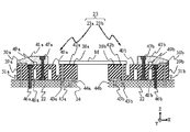
- FIG. 6 is an enlarged cross-sectional view of the mask holding unit 23 in the mask stage MS of FIG.
- the first mask holding portion 23 a and the second mask holding portion 23 b have a Z-axis symmetric structure with respect to the opening 24.
- the configuration of the first mask holding portion 23a on the ⁇ X side with respect to the opening 24 will be described in detail.
- each configuration of the second mask holding unit 23b is expressed by replacing the subscript of each configuration of the first mask holding unit 23a from a to b. To do.
- the first mask holding portion 23 a includes a holding portion 38 a (first member) that holds the lower surface of the mask M, a lower block portion 39 a (second member) that is partially fixed to the stage body 22, and a deformation of the mask M. Accordingly, the holding unit 38a changes the position of the holding unit 38a with respect to the lower block unit 39a along the X-axis direction (the relative positional relationship between the holding unit 38a and the lower block unit 39a changes).
- the hinge part 40a (connecting member, support part) which is a support part which supports 38a, and the upper block part 41a which a part is fixed to the lower block part 39a and arrange
- the holding unit 38a is formed by penetrating the holding surface 42a for holding the mask M by vacuum suction, and penetrating the holding unit 38a and the stage body 22 from the holding surface 42a, and communicating with a vacuum apparatus (not shown).
- the holding surface 42a has high flatness, and the mask M placed on the holding surface 42a is sucked and held by setting the mask suction tube 43a to a predetermined negative pressure.
- a plurality of first communication pipes 45a are formed along the Y-axis direction.
- the gap (the distance between the upper surface of the stage main body 22 and the surface of the first suction pocket 44a facing the upper surface) of the first suction pocket 44a is 10 ⁇ m.
- the pressure that can be set in the first suction pocket 44a via the first communication pipe 45a is 0 Pa to -55 kPa, and the plurality of first communication pipes 45a independently sets the intake pressure. it can.
- the first suction pocket 44a and the first communication pipe 45a will be described later.
- the lower block portion 39a is fixed to the stage body 22 by the first connecting portion 46a, and the upper block portion 41a is fixed by the second connecting portion 47a.
- a first slit 48a is formed so that an opening is formed on the stage body 22 side.
- the upper block portion 41a has a second slit 49a corresponding to the first slit 48a and the Z direction so that an opening is formed on the upper surface side of the lower block portion 39a.
- a second suction pocket 50a (working surface) is formed between the lower surface of the upper block portion 41a and the upper surface of the lower block portion 39a, and the inside of the lower block portion 39a and the stage main body 22 from the second suction pocket 50a.
- a second communication pipe 51a gas flow port that penetrates and communicates with a vacuum device (not shown) is formed.
- a plurality of second communication pipes 51a are formed along the Y-axis direction.
- the gap of the second suction pocket 50a (the distance between the upper surface of the lower block portion 39a and the surface of the second suction pocket 50a facing the upper surface) is 10 ⁇ m.
- the pressure that can be set in the second suction pocket 50a via the second communication pipe 51a is 0 Pa to -55 kPa as in the first suction pocket 44a.
- the plurality of second communication pipes 51a can independently set the intake pressure.
- the second suction pocket 50a and the second communication pipe 51a will be described later.
- Hinge part 40a is a support part which connects holding part 38a and lower block part 39a in this embodiment.
- a holding portion 38a and a lower block portion 39a are integrally formed.
- the hinge portion 40a, the holding portion 38a, and the lower block portion 39a are made of ceramic.
- the lower block portion 39a is fixed to the stage main body 22 by the first connecting portion 46a. Therefore, the hinge portion 40a is connected to the holding portion 38a and the lower block portion 39a so that the holding portion 38a can be displaced in the X-axis direction with respect to the lower block portion 39a.
- the first suction pocket 44a and the first communication pipe 45a, and the second suction pocket 50a and the second communication pipe 51a will be described with reference to FIG.
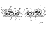
- FIG. 7 is an enlarged cross-sectional view of the mask holding unit 23 shown as an example of a modification of the mask M in the present embodiment.
- the intake pressures of the first communication pipe 45a and the second communication pipe 51a can be independently adjusted.
- the lower block portion 39a is fixed to the stage body 22 by setting the intake pressure of the second communication tube 51a higher than the intake pressure of the first communication tube 45a to a predetermined differential pressure.
- the holding portion 38a With the first connecting portion 46a (not shown in FIG. 7A) as a fulcrum, the holding portion 38a is driven counterclockwise around the Y axis (the holding portion 38a is inclined upward in the + X direction). In other words, the holding portion 38a is inclined so as to become higher as the portion is located on the + X direction side. Therefore, a counterclockwise bending moment acts around the Y axis at the ⁇ X side end of the mask M.
- the configuration of the first mask holding portion 23a and the second mask holding portion 23b of the present embodiment is symmetric with respect to the opening 24 as described above. Therefore, also in the 2nd mask holding
- the holding portion 38b first member
- the holding portion 38b tilts downward in the + X direction.
- the holding portion 38b is inclined so as to become higher as the portion is located on the ⁇ X direction side. Therefore, a clockwise bending moment acts on the + X side end of the mask M around the Y axis.
- the bending moment is a force that deforms the mask M.
- the lower block portion 39a is connected to the first connection pipe 45a.
- the portion 46a (not shown in FIG. 7B) as a fulcrum
- the holding portion 38a is driven clockwise around the Y axis (the holding portion 38a is inclined downward in the + X direction).
- the holding portion 38a is inclined so as to become higher as the portion is located on the ⁇ X direction side. Therefore, a clockwise bending moment acts on the ⁇ X side end portion of the mask M around the Y axis.
- the first connecting portion 46b in which the lower block portion 39b is fixed to the stage body 22 is used as a fulcrum.
- the holding portion 38b is driven counterclockwise around the Y axis (the holding portion 38b is inclined upward in the + X direction).
- the holding portion 38b is inclined so as to become higher as the portion is located on the + X direction side. Therefore, a counterclockwise bending moment acts on the + X side end of the mask M around the Y axis. Therefore, the mask M is deformed into a convex shape in the ⁇ Z direction.
- the intake pressure of the second communication pipe 51a is changed to the first communication pipe 45a.
- the posture (tilt, etc.) of the holding portion 38a (holding surface 42a) is changed from a state parallel to the X axis to the + X direction.
- the larger the amount of change in the inclination (posture) of the holding portion 38a the more the ⁇ X side end of the mask M is displaced in the + X direction with respect to the stage main body 22.
- the hinge portion 40a connected to the holding portion 38a extends in the + X direction with respect to the lower block 39a. That is, the relative positional relationship between the holding portion 38a and the lower block 39a changes via the hinge portion 40a.
- the hinge portion 40a connected to the holding portion 38a contracts in the ⁇ X direction with respect to the lower block 39a. That is, the relative positional relationship between the holding portion 38a and the lower block 39a changes via the hinge portion 40a.
- the hinge portion 40a in the present embodiment causes the holding portion 38a to change the position of the holding portion 38a along the X-axis direction according to a change in the inclination (posture) of the holding portion 38a (holding surface 42a). It is connected.
- the shearing force generated in the X-axis direction at the interface between the holding surface 42a of the holding portion 38a and the mask M can be suppressed. Therefore, the force (for example, suction force) for holding the mask M in the holding portion 38a is not reduced by the shearing force generated at the interface between the holding surface 42a and the mask M, so that the mask M is not detached from the holding portion 38a. , It can be deformed to a desired shape. Therefore, the change in the pattern image plane of the mask M due to the aberration variation of the projection optical system PL can be sufficiently corrected, and the pattern formed on the mask M can be accurately exposed to the substrate W.
- the force for example, suction force
- the first mask holding portion 23a is movable. The range becomes large, and the bending moment around the Y axis can be efficiently applied to the mask M.
- the suction pressure of the first communication pipe 45a and the second communication pipe 51a is ⁇ 55 kPa at the maximum, but may not be ⁇ 55 kPa, and the suction pressure may be set according to the deformation amount of the mask M. It may be higher.
- a negative pressure is set in the first suction pocket 44a and the second suction pocket 50a, but a positive pressure may be used.
- a compression device may be connected to the first communication pipe 45a and the second communication pipe 51a.
- the first suction pocket 44a and the first communication pipe 45a, and the second suction pocket 50a and the second communication pipe 51a form two drive parts that drive the holding part 38a independently.
- the number of driving units may not be two. For example, there may be three or more, and the presence of many drive units makes it possible to drive the holding unit 38a with higher accuracy.
- the first suction pocket 44a and the second suction pocket 50a communicate with the first communication pipe 45a and the second communication pipe 51a, respectively. There may be no pocket 50a, or only one of them may be present.
- the other end of the first communication tube 45a connected to a vacuum device (not shown) is connected to the lower surface of the holding portion 38a, and the inside of the first communication tube 45a is set to a negative pressure. To do.
- the gap between the first suction pocket 44a and the second suction pocket 50a is 10 ⁇ m, but may not be 10 ⁇ m. Further, the gap between the first suction pocket 44a and the second suction pocket 50a may be different.
- the hinge portion 40a is formed integrally with the lower block portion 39a and the holding portion 38a, but may not be formed integrally.
- the hinge part 40a may be formed by a separate leaf spring and fixed to the lower block part 39a and the holding part 38a.
- the separate member is, for example, stainless steel or titanium.
- the first block 48a is provided with a first slit 48a
- the upper block 41a is provided with a second slit 49a.
- These slits may not be provided.
- each of the first slit 48a and the second slit 49a is cut one by one.
- the number of slits is not limited to one, and a plurality of slits may be cut.
- FIG. 8 a configuration as shown in FIG. 8 may be adopted instead of the slit.
- a portion different from the configuration of FIG. 6 is a rotating portion 52a formed in the block portion 50a and fixed to the stage main body 22 by a third connecting portion 57a.
- a third communication pipe 54a (gas flow port) and a fourth communication pipe 56a connected to a vacuum device (not shown) on the left and right of the rotating part 52a are respectively provided with a third suction pocket 53a (work surface) and a fourth suction pocket 55a. It communicates facing the (working surface).
- the holding portion 38a is driven with the rotating portion 52a serving as a fulcrum due to the differential pressure between the intake pressure of the third suction pocket 53a and the intake pressure of the fourth suction pocket 55a, and the mask M is rotated on the Y axis.
- a rotating or counterclockwise bending moment acts.
- the hinge portion 40a may not be a hinge as long as it is an elastic body that is displaced at least in the X-axis direction.
- a spring member may be used, or a hinge and a spring member may be combined. Also good.
- the holding unit 38a may be driven using electromagnetic force.
- a magnet is installed at the position of the first suction pocket 44a and the second suction pocket 50a, and the stage body 22 facing the magnet provided in the first suction pocket 44a and the magnet provided in the second suction pocket 50a
- Two voice coil motors may be configured by installing a coil on each of the upper surfaces of the opposed lower block portions 39a, and the holding portion 38a may be driven by electromagnetic force generated by these voice coil motors.
- the holding unit 38a may be driven using a piezoelectric element.
- the piezo elements may be installed at the positions of the first suction pocket 44a and the second suction pocket 50a, and the holding portion 38a may be driven by pressing the surface facing each of the piezo elements.
- FIG. 9 is a schematic flowchart for explaining an example of the operation of the exposure apparatus EX in the present embodiment, and shows an example of basic exposure processing steps.
- the mask M is transported to the holding part 38a (38b) of the mask stage MS and is sucked and held by driving a transport system including a robot arm (not shown) (step 101).
- the substrate W is loaded onto the substrate table WT by driving a transport system including a robot arm (not shown) (step 102).
- step 103 alignment of the loaded substrate W is executed (step 103). Specifically, first, a plurality of substrate alignment marks (not shown) formed in a plurality of exposure regions (shots) of the substrate W are detected by the substrate alignment system WA, and Japanese Patent Application Laid-Open No. 61-44429 (corresponding) The alignment of all exposure areas (shots) of the substrate W is estimated by an EGA (Enhanced Global Alignment) process disclosed in US Pat. No. 4,780,617. Subsequently, a substrate reference mark (not shown) provided on the substrate table WT is detected by the substrate alignment system WA, and the positional relationship between the substrate alignment system WA and the substrate reference mark is measured. Further, while the EGA processing and the substrate reference mark are detected in this step 103, the position (focus position) and posture ( ⁇ X, ⁇ Y) in the Z direction of each exposure region (shot) of the substrate W are sequentially measured. To go.
- EGA Enhanced Global Alignment
- the immersion area AR is formed (step 104). Specifically, the liquid supply operation on the substrate W (substrate table WT) is started by driving the liquid supply device, and the liquid recovery from the substrate W (substrate table WT) is started by driving the liquid recovery device.
- a liquid immersion area AR is formed between the lower surface of the liquid immersion device 15 and the lower surface of the last optical element 14 (the lower surface of the projection optical system PL) and the substrate W (substrate table WT).
- step 105 it is determined whether or not the substrate W to be exposed is the first substrate in the lot.
- step 105 When it is determined in step 105 that the substrate W to be exposed is the first substrate in the lot, the lower surface of the mask M with respect to the reference surface 61 of the reference member 60 (not shown) by the surface position measurement system (not shown).
- the Z position of the pattern surface) is measured, and the amount of displacement in the Z direction of the mask M with respect to the reference surface 61 is measured (step 106).
- the control device CONT drives the mask stage MS via a mask stage driving device (not shown), and the surface position measurement system (not shown) also connects the reference surface 61 of the reference member 60 and the mask M.
- Detection light is sequentially irradiated to a plurality of points on the lower surface (pattern surface).
- the Z position of the lower surface (pattern surface) of the mask M with respect to the reference surface 61 is measured, and the shape of the mask M is measured.
- a deformation amount for deforming the mask M by the mask holding unit 23 is obtained (step 107).
- the provisional deformation amount of the mask M for correcting the change in the pattern image plane of the mask M calculated in advance and the set value of the lens control LC, the provisional deformation amount of the mask M, Based on the shape of the mask M measured in step 106, the deformation amount of the mask M to be deformed by the mask holding unit 23 in the subsequent step 108 is calculated.
- the preliminarily calculated provisional deformation amount of the mask M and the set value of the lens control LC are the pattern image of the mask M due to the aberration variation of the projection optical system PL when a lot of substrates are exposed in an arbitrary lot.
- the amount of change of the surface is obtained, and the change of the pattern image surface is obtained. That is, in this embodiment, the provisional deformation amount of the mask M and the set value of the lens control are calculated in advance for each lot.
- the mask M is deformed by tilting the holding portion 38a (38b) based on the deformation amount of the mask M calculated in step 107 (step 108).
- the lens control LC is set based on the set value of the lens control LC calculated in step 107. That is, in the present embodiment, the deformation of the pattern of the mask M is corrected by cooperating the deformation of the shape of the mask M and the lens control LC.
- step 109 alignment of the loaded mask M is executed (step 109). Specifically, a mask alignment mark (not shown) formed on the mask M and a mask reference mark (not shown) provided on the substrate table WT are formed in the liquid immersion area AR and projection optics formed in step 104. It is simultaneously detected by the mask alignment system MA via the system PL, and the positional relationship between the mask alignment mark and the mask reference mark is measured. At this time, the substrate alignment system WA and the mask are determined based on the positional relationship between the substrate alignment system WA and the substrate reference mark measured in step 103 and the positional relationship between the mask alignment mark and the mask reference mark measured in step 109. A positional relationship with the alignment mark is calculated, and a baseline amount that is an interval between the substrate alignment system WA and the pattern image of the mask M is calculated.
- step 103 the arrangement of exposure areas (shots) estimated in step 103, the position (focus position) and orientation ( ⁇ X, ⁇ Y) in the Z direction of each exposure area (shot) measured in step 103, and step 109
- the pattern image of the mask M is sequentially exposed to each exposure region (each shot) on the substrate W based on the baseline amount measured in (Step 110).
- step 105 if it is determined in step 105 that the substrate W to be exposed is not the first substrate in the lot, the substrate W is exposed through the immersion area AR (step 110).
- step 110 After the substrate W is exposed in step 110, it is determined whether or not this substrate W is the last substrate in the lot (step 111).
- step 111 If it is determined in step 111 that the substrate W is the last substrate in the lot, the used mask M is unloaded from the mask stage MS, and in step 101 a new mask M is loaded on the mask stage MS.
- step 111 if it is determined in step 111 that the substrate W is not the last substrate in the lot, a new substrate W is loaded on the substrate table WT in step 102.
- the mask M is desired according to the change in the pattern image plane of the mask M caused by the aberration variation of the projection optical system PL (in cooperation with the lens control LC).
- the change in the pattern image plane of the mask M can be sufficiently corrected, and the pattern formed on the mask M can be accurately exposed to the substrate W.
- the set value of the lens control LC and the deformation amount of the shape of the mask M are calculated for each lot. However, they may not be calculated for each lot, for example, for each substrate to be exposed and for each substrate.
- the shape of the lens control LC and the mask M may be set.
- the provisional deformation amount of the mask M for correcting the change in the pattern image plane of the mask M and the set value of the lens control LC are calculated in advance.
- the aberration of the projection optical system PL is measured at a predetermined timing, and the image plane shape of the pattern image of the mask M caused by this aberration is corrected.
- the set value of the lens control LC and the deformation amount of the mask M may be obtained.
- the change in the pattern image plane of the mask M is corrected by cooperating the setting of the lens control LC and the deformation of the shape of the mask M.
- correction may be performed by deforming only the shape of the mask M without using the lens control LC.
- a provisional deformation amount of the mask M that corrects a change in the pattern image plane of the mask M due to an aberration variation of the projection optical system PL when a lot of substrates are exposed in an arbitrary lot is obtained in advance.
- the deformation amount of the mask M deformed by the mask holding unit 23 is calculated in step 108, and the mask M can be deformed. That's fine.
- FIG. 10 is a modification of the mask holding unit 23 according to the first embodiment.
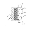
- FIG. 11A is an enlarged view of the first mask holding portion 68a (first holding portion) in FIG. 10, and FIG. 11B is a cross-sectional view taken along the line CC in the enlarged view of the first mask holding portion 68a in FIG. 11A. .
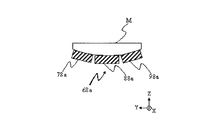
- the configuration different from the mask holding portion 23 includes divided holding portions 78a, 88a, and 98a divided into three along the Y axis, as shown in FIG.
- the first mask holding unit 68a and the second mask holding unit 68b (second holding unit) including the divided holding units 78b, 88b, and 98b are provided.
- first mask holding portion 68a and the second mask holding portion 68b have a Z-axis symmetric structure with respect to the opening 24, only the first mask holding portion 68a will be described.
- the first mask holding portion 68a includes divided holding portions 78a, 88a, and 98a that suck and hold the ⁇ X side end of the mask M at three locations along the Y axis.
- a hinge portion 40a shown in FIG. 6 is connected to each of the divided holding portions 78a, 88a, 98a (not shown in FIG. 11).
- the hinge portion 40a connects the holding surfaces holding the mask M of the divided holding portions 78a, 88a, 98a to the divided holding portions 78a, 88a, 98a so as to be inclined in the Y-axis direction. ing.
- the mask M can be held by suction with the divided holding portions 78a, 88a, and 98a according to the shape of the lower surface of the mask M, as shown in FIG. Distortion occurring in the held mask M can be suppressed.
- FIG. 12 is an enlarged cross-sectional view of the first mask holding portion 23a on the ⁇ X side in the present embodiment.
- the description of the configuration of the second mask holding part 23b is omitted.
- the holding portion 38a is X.
- a support portion that is supported so as to be displaceable in the axial direction it is installed between the lower block portion 39a and the holding portion 38a.
- the guide portion 58a is a linear guide composed of a rail (not shown) extending in the X-axis direction and a movable body (not shown) fitted to the rail.
- the movable body is fitted to the rail via a plurality of balls (rolling bodies) that roll along the X-axis direction, and the rail is moved along the X-axis direction. Can be moved.
- the holding portion 38a rotates counterclockwise around the Y axis. Driven (holding portion 38a is tilted upward in the + X direction), and a counterclockwise bending moment acts on the ⁇ X side end of mask M on the Y axis (see FIG. 7A). At that time, the ⁇ side end portion of the mask M is displaced in the + X direction by a predetermined displacement amount, but the holding portion 38a fixed to the movable body (not shown) of the guide portion 58a is lowered according to this displacement amount. It is displaced in the + X direction with respect to the block portion 39a.
- the guide portion 58a in the present embodiment changes the position of the holding portion 38a in the X-axis direction according to the inclination (posture) of the holding portion 38a.
- the guide portion 58a supports the holding portion 38a almost independently of other configurations (for example, the lower block portion 39a). Therefore, when the holding portion 38a is displaced, the position of the holding portion 38a can be smoothly changed in the X-axis direction without applying stress to other components.
- the shearing force generated in the X-axis direction can be suppressed at the interface between the mask M and the holding surface 42a of the holding portion 38a, and the mask M can be deformed to a desired shape. Therefore, the change in the pattern image plane of the mask M due to the aberration variation of the projection optical system PL can be sufficiently corrected, and the pattern formed on the mask M can be accurately exposed to the substrate W.
- the holding portion 38a is fixed to a movable body (not shown) of the guide portion 58a, but the movable body may be the holding portion 38a.
- a linear guide using a plurality of rolling elements that roll in the X-axis direction is used as a support portion that supports the holding portion 38a so as to be displaceable in the X-axis direction.
- an air guide that supports the holding portion 38a by air pressure so as to be displaceable in the X-axis direction without contact with the lower block portion 39a may be employed, or the holding portion 38a may be moved in the X-axis direction by electromagnetic force.
- a uniaxial linear motor to be moved may be employed.
- the amount of movement of the holding portion 38a in the X-axis direction is controlled by the control device CONT in accordance with the amount of displacement in the X direction of the end of the mask M that is displaced by the bending moment (see FIG. 1).
- two mask patterns are synthesized on a substrate via a projection optical system, and one shot on the substrate is obtained by one scanning exposure.
- the present invention can also be applied to an exposure apparatus that performs double exposure of regions almost simultaneously.
- the present invention can also be applied to proximity type exposure apparatuses, mirror projection aligners, and the like.
- the type of the exposure apparatus EX is not limited to an exposure apparatus for manufacturing a semiconductor element that exposes a semiconductor element pattern on the substrate W, but an exposure apparatus for manufacturing a liquid crystal display element or a display, a thin film magnetic head, an imaging element. (CCD), micromachine, MEMS, DNA chip, or an exposure apparatus for manufacturing a reticle or mask can be widely applied.
- the mask-side laser interferometer 19 and the substrate-side laser interferometer 17 are used to measure the positions of the mask stage MS and the substrate table WT.
- an encoder system that detects scales (diffraction gratings) provided on the mask stage MS and the substrate table WT may be used.
- a hybrid system including at least one of the mask side laser interferometer 19 and the substrate side laser interferometer 17 and the encoder system is used, and at least one of the mask side laser interferometer 19 and the substrate side laser interferometer 17 is used. It is preferable to calibrate the measurement result of the encoder system using one measurement result.
- the position control of the stage may be performed by switching between at least one of the mask side laser interferometer 19 and the substrate side laser interferometer 17 and the encoder system or using both.
- an ArF excimer laser is used.
- a solid-state laser light source such as a DFB semiconductor laser or a fiber laser
- an optical amplification unit having a fiber amplifier and a wavelength conversion unit, etc.
- a harmonic generator that outputs pulsed light with a wavelength of 193 nm may be used.
- each illumination area and the projection area described above are rectangular, but other shapes such as an arc shape may be used.
- a light transmissive mask in which a predetermined light shielding pattern (or phase pattern / dimming pattern) is formed on a light transmissive substrate is used.
- a variable shaped mask that forms a transmission pattern, a reflection pattern, or a light emission pattern based on electronic data of a pattern to be exposed ( An electronic mask, an active mask, or an image generator may also be used.
- the variable shaping mask includes, for example, a DMD (Digital Micro-mirror Device) which is a kind of non-light emitting image display element (spatial light modulator).
- the variable shaping mask is not limited to DMD, and a non-light emitting image display element described below may be used instead of DMD.
- the non-light-emitting image display element is an element that spatially modulates the amplitude (intensity), phase, or polarization state of light traveling in a predetermined direction
- a transmissive liquid crystal modulator is a transmissive liquid crystal modulator.
- An electrochromic display (ECD) etc. are mentioned as an example other than a display element (LCD: Liquid * Crystal * Display).
- the reflective spatial light modulator includes a reflective mirror array, a reflective liquid crystal display element, an electrophoretic display (EPD), electronic paper (or electronic ink), and a light diffraction type.
- An example is a light bulb (Grating Light Valve).
- a pattern forming apparatus including a self-luminous image display element may be provided instead of the variable shaping mask including the non-luminous image display element.
- an illumination system is unnecessary.
- the self-luminous image display element include CRT (Cathode Ray Tube), inorganic EL display, organic EL display (OLED: Organic Light Emitting Diode), LED display, LD display, field emission display (FED: Field Emission). Display), plasma display (PDP: Plasma Display Panel), and the like.
- a solid light source chip having a plurality of light emitting points, a solid light source chip array in which a plurality of chips are arranged in an array, or a plurality of light emitting points on a single substrate A built-in type or the like may be used to form a pattern by electrically controlling the solid light source chip.
- the solid light source element may be inorganic or organic.
- an exposure apparatus (lithography system) that exposes a line-and-space pattern on a substrate W by forming interference fringes on the substrate W.
- the present invention can also be applied.
- the exposure apparatus EX of the present embodiment is manufactured by assembling various subsystems including each component so as to maintain predetermined mechanical accuracy, electrical accuracy, and optical accuracy.
- various optical systems are adjusted to achieve optical accuracy
- various mechanical systems are adjusted to achieve mechanical accuracy
- various electrical systems are Adjustments are made to achieve electrical accuracy.
- the assembly process from the various subsystems to the exposure apparatus includes mechanical connection, electrical circuit wiring connection, pneumatic circuit piping connection and the like between the various subsystems.
- an assembly process for each subsystem Before the assembly process from the various subsystems to the exposure apparatus, there is an assembly process for each subsystem. When the assembly process of the various subsystems to the exposure apparatus is completed, comprehensive adjustment is performed to ensure various accuracies as the entire exposure apparatus.
- the exposure apparatus is preferably manufactured in a clean room where the temperature, cleanliness, etc. are controlled.
- FIG. 13 is a flowchart showing an example of a microdevice manufacturing process.
- a microdevice such as a semiconductor device includes a step 201 for designing a function / performance of the microdevice, a step 202 for producing a mask (reticle) based on the design step, and a substrate which is a base material of the device.
- Substrate processing step 204 including substrate processing (exposure processing) including exposing the substrate with exposure light through the mask M and developing the exposed substrate according to the above-described embodiment.
- the device is manufactured through a device assembly step (including processing processes such as a dicing process, a bonding process, and a package process) 205, an inspection step 206, and the like.
- M mask (object, plate-like object, optical member, plate-like optical member), 1: mask stage device (holding device, base material), MS: mask stage, 22: stage main body (base), 23: mask holding unit (Holding part), 23a: first mask holding part (first holding part), 23b: second mask holding part (second holding part), 25a, 25b: mover, 38a, 38b: holding part (first 1 member), 39a, 39b: lower block portion (second member), 40a: hinge portion (connecting member, support portion), 44a: first suction pocket (working surface), 45a, 45b: first communication pipe (gas) (Flow port), 46a, 46b: first connecting portion, 50a: second adsorption pocket (working surface), 51a, 51b: second communication pipe (gas flow port), 53a: third adsorption pocket (working surface), 54a : Third communication pipe (gas flow port), 55a: No.
Landscapes
- Physics & Mathematics (AREA)
- General Physics & Mathematics (AREA)
- Exposure And Positioning Against Photoresist Photosensitive Materials (AREA)
- Container, Conveyance, Adherence, Positioning, Of Wafer (AREA)
- Exposure Of Semiconductors, Excluding Electron Or Ion Beam Exposure (AREA)
Abstract
Priority Applications (4)
| Application Number | Priority Date | Filing Date | Title |
|---|---|---|---|
| KR1020137024479A KR101962487B1 (ko) | 2011-02-22 | 2012-02-17 | 유지 장치, 노광 장치, 및 디바이스의 제조 방법 |
| US13/985,832 US9746787B2 (en) | 2011-02-22 | 2012-02-17 | Holding apparatus, exposure apparatus and manufacturing method of device |
| JP2013501003A JPWO2012115002A1 (ja) | 2011-02-22 | 2012-02-17 | 保持装置、露光装置、及びデバイスの製造方法 |
| US15/671,533 US10416573B2 (en) | 2011-02-22 | 2017-08-08 | Holding apparatus, exposure apparatus and manufacturing method of device |
Applications Claiming Priority (2)
| Application Number | Priority Date | Filing Date | Title |
|---|---|---|---|
| JP2011-035412 | 2011-02-22 | ||
| JP2011035412 | 2011-02-22 |
Related Child Applications (3)
| Application Number | Title | Priority Date | Filing Date |
|---|---|---|---|
| US13/985,832 A-371-Of-International US9746787B2 (en) | 2011-02-22 | 2012-02-17 | Holding apparatus, exposure apparatus and manufacturing method of device |
| US15/671,533 Division US10416573B2 (en) | 2011-02-22 | 2017-08-08 | Holding apparatus, exposure apparatus and manufacturing method of device |
| US15/671,533 Continuation US10416573B2 (en) | 2011-02-22 | 2017-08-08 | Holding apparatus, exposure apparatus and manufacturing method of device |
Publications (1)
| Publication Number | Publication Date |
|---|---|
| WO2012115002A1 true WO2012115002A1 (fr) | 2012-08-30 |
Family
ID=46720783
Family Applications (1)
| Application Number | Title | Priority Date | Filing Date |
|---|---|---|---|
| PCT/JP2012/053803 Ceased WO2012115002A1 (fr) | 2011-02-22 | 2012-02-17 | Dispositif de retenue, dispositif d'exposition et procédé de production pour le dispositif |
Country Status (4)
| Country | Link |
|---|---|
| US (2) | US9746787B2 (fr) |
| JP (3) | JPWO2012115002A1 (fr) |
| KR (1) | KR101962487B1 (fr) |
| WO (1) | WO2012115002A1 (fr) |
Cited By (2)
| Publication number | Priority date | Publication date | Assignee | Title |
|---|---|---|---|---|
| JP2016539499A (ja) * | 2013-11-08 | 2016-12-15 | キャノン・ナノテクノロジーズ・インコーポレーテッド | 改善されたオーバレイ補正のための低接触インプリントリソグラフィテンプレート用チャックシステム |
| WO2025191794A1 (fr) * | 2024-03-14 | 2025-09-18 | 株式会社ニコン | Dispositif de déformation d'élément optique, dispositif de correction d'aberration et dispositif optique |
Families Citing this family (6)
| Publication number | Priority date | Publication date | Assignee | Title |
|---|---|---|---|---|
| WO2012115002A1 (fr) * | 2011-02-22 | 2012-08-30 | 株式会社ニコン | Dispositif de retenue, dispositif d'exposition et procédé de production pour le dispositif |
| JP6207671B1 (ja) * | 2016-06-01 | 2017-10-04 | キヤノン株式会社 | パターン形成装置、基板配置方法及び物品の製造方法 |
| WO2019082727A1 (fr) * | 2017-10-24 | 2019-05-02 | キヤノン株式会社 | Dispositif d'exposition et procédé de fabrication d'articles |
| JP2019079029A (ja) * | 2017-10-24 | 2019-05-23 | キヤノン株式会社 | 露光装置および物品の製造方法 |
| JP7022621B2 (ja) * | 2018-03-08 | 2022-02-18 | キヤノン株式会社 | 制振装置、リソグラフィ装置、および物品の製造方法 |
| KR102898922B1 (ko) * | 2022-01-18 | 2025-12-10 | 야마하 로보틱스 가부시키가이샤 | 피가공물 홀딩 시스템 및 피가공물 홀딩 장치 |
Citations (9)
| Publication number | Priority date | Publication date | Assignee | Title |
|---|---|---|---|---|
| JPS63209126A (ja) * | 1987-02-26 | 1988-08-30 | Canon Inc | 露光装置 |
| JPS6454392A (en) * | 1987-08-26 | 1989-03-01 | Nec Corp | Flap stage |
| JPH0240594A (ja) * | 1988-07-29 | 1990-02-09 | Nec Corp | あおりステージ |
| JP2003133223A (ja) * | 2001-10-30 | 2003-05-09 | Canon Inc | 露光装置 |
| JP2007515799A (ja) * | 2003-12-24 | 2007-06-14 | エーエスエムエル ネザーランズ ビー.ブイ. | リソグラフィ装置およびデバイス製造方法 |
| JP2007184328A (ja) * | 2006-01-04 | 2007-07-19 | Nsk Ltd | 露光装置 |
| JP2008170775A (ja) * | 2007-01-12 | 2008-07-24 | San Ei Giken Inc | 露光装置 |
| JP2009036925A (ja) * | 2007-07-31 | 2009-02-19 | Hitachi High-Technologies Corp | 露光装置、露光方法、及び表示用パネル基板の製造方法 |
| WO2009125867A1 (fr) * | 2008-04-11 | 2009-10-15 | 株式会社ニコン | Dispositif à étage, appareil d'exposition, et procédé de fabrication du dispositif |
Family Cites Families (40)
| Publication number | Priority date | Publication date | Assignee | Title |
|---|---|---|---|---|
| US4370054A (en) * | 1981-04-02 | 1983-01-25 | Canon Kabushiki Kaisha | Projection exposure apparatus |
| US4780617A (en) | 1984-08-09 | 1988-10-25 | Nippon Kogaku K.K. | Method for successive alignment of chip patterns on a substrate |
| JPS6144429A (ja) | 1984-08-09 | 1986-03-04 | Nippon Kogaku Kk <Nikon> | 位置合わせ方法、及び位置合せ装置 |
| JPS6380498A (ja) | 1986-09-24 | 1988-04-11 | 株式会社日立製作所 | 薄膜el素子 |
| JP2840314B2 (ja) | 1989-08-30 | 1998-12-24 | キヤノン株式会社 | 投影露光装置 |
| JP2703345B2 (ja) * | 1989-06-08 | 1998-01-26 | 株式会社東芝 | 位置決め装置 |
| JP2897355B2 (ja) | 1990-07-05 | 1999-05-31 | 株式会社ニコン | アライメント方法,露光装置,並びに位置検出方法及び装置 |
| US5424552A (en) | 1991-07-09 | 1995-06-13 | Nikon Corporation | Projection exposing apparatus |
| JPH0541344A (ja) | 1991-08-05 | 1993-02-19 | Nikon Corp | 投影露光装置 |
| US5534970A (en) | 1993-06-11 | 1996-07-09 | Nikon Corporation | Scanning exposure apparatus |
| JP3555230B2 (ja) | 1994-05-18 | 2004-08-18 | 株式会社ニコン | 投影露光装置 |
| JPH0982606A (ja) * | 1995-09-13 | 1997-03-28 | Nikon Corp | レチクルホルダ |
| JP3305188B2 (ja) * | 1996-02-07 | 2002-07-22 | キヤノン株式会社 | 原版、原版保持装置およびこれを用いた露光装置ならびにディバイス製造方法 |
| US5854819A (en) * | 1996-02-07 | 1998-12-29 | Canon Kabushiki Kaisha | Mask supporting device and correction method therefor, and exposure apparatus and device producing method utilizing the same |
| CN1244018C (zh) | 1996-11-28 | 2006-03-01 | 株式会社尼康 | 曝光方法和曝光装置 |
| KR100512450B1 (ko) | 1996-12-24 | 2006-01-27 | 에이에스엠엘 네델란즈 비.브이. | 두개의물체홀더를가진이차원적으로안정화된위치설정장치와이런위치설정장치를구비한리소그래픽장치 |
| US6549271B2 (en) * | 1997-01-28 | 2003-04-15 | Nikon Corporation | Exposure apparatus and method |
| EP0900412B1 (fr) | 1997-03-10 | 2005-04-06 | ASML Netherlands B.V. | Appareil lithographique comprenant un dispositif de positionnement pourvu de deux supports d'objet |
| US6208407B1 (en) | 1997-12-22 | 2001-03-27 | Asm Lithography B.V. | Method and apparatus for repetitively projecting a mask pattern on a substrate, using a time-saving height measurement |
| KR100819239B1 (ko) | 1998-03-11 | 2008-04-03 | 가부시키가이샤 니콘 | 자외 레이저 장치, 레이저 장치, 노광 장치와 노광 방법, 디바이스 제조 방법, 자외광 조사 장치, 물체 패턴 검출 장치, 자외광 조사 방법 및 물체 패턴 검출 방법 |
| AU2747999A (en) | 1998-03-26 | 1999-10-18 | Nikon Corporation | Projection exposure method and system |
| JP2001023886A (ja) | 1999-07-08 | 2001-01-26 | Nikon Corp | 試料保持装置及び露光装置 |
| WO2001035168A1 (fr) | 1999-11-10 | 2001-05-17 | Massachusetts Institute Of Technology | Lithographie interferentielle utilisant des faisceaux de balayage a verrouillage de phase |
| JP2001148335A (ja) * | 1999-11-18 | 2001-05-29 | Canon Inc | 露光装置およびデバイス製造方法 |
| KR100855527B1 (ko) * | 2001-02-13 | 2008-09-01 | 가부시키가이샤 니콘 | 유지장치, 유지방법, 노광장치 및 디바이스 제조방법 |
| KR100815222B1 (ko) | 2001-02-27 | 2008-03-19 | 에이에스엠엘 유에스, 인크. | 리소그래피 장치 및 적어도 하나의 레티클 상에 형성된 적어도 두 개의 패턴으로부터의 이미지로 기판 스테이지 상의 필드를 노출시키는 방법 |
| US6791669B2 (en) * | 2001-04-12 | 2004-09-14 | Nikon Corporation | Positioning device and exposure apparatus including the same |
| TW529172B (en) | 2001-07-24 | 2003-04-21 | Asml Netherlands Bv | Imaging apparatus |
| CN1484850A (zh) * | 2001-08-08 | 2004-03-24 | 尼康株式会社 | 载台系统及曝光装置,以及元件制造方法 |
| TWI338323B (en) | 2003-02-17 | 2011-03-01 | Nikon Corp | Stage device, exposure device and manufacguring method of devices |
| US6950175B2 (en) * | 2003-06-02 | 2005-09-27 | Asml Holding N.V. | System, method, and apparatus for a magnetically levitated and driven reticle-masking blade stage mechanism |
| WO2006016584A1 (fr) | 2004-08-09 | 2006-02-16 | Nikon Corporation | Dispositif de mesure des caractéristiques optiques, méthode de mesure des caractéristiques optiques, dispositif d'exposition, méthode d'exposition, et une méthode pour fabriquer le dispositif |
| JP2006080281A (ja) * | 2004-09-09 | 2006-03-23 | Nikon Corp | ステージ装置、ガスベアリング装置、露光装置、並びにデバイス製造方法 |
| WO2007119821A1 (fr) | 2006-04-14 | 2007-10-25 | Nikon Corporation | Procede et appareil d'exposition, et procede de fabrication du dispositif |
| JP2007328008A (ja) * | 2006-06-06 | 2007-12-20 | Nsk Ltd | 露光装置 |
| US7675607B2 (en) * | 2006-07-14 | 2010-03-09 | Asml Netherlands B.V. | Lithographic apparatus and device manufacturing method |
| JP2010212386A (ja) * | 2009-03-10 | 2010-09-24 | Nikon Corp | 周辺露光方法、周辺露光装置並びにデバイス製造方法。 |
| KR101494493B1 (ko) * | 2009-08-07 | 2015-02-17 | 가부시키가이샤 니콘 | 이동체 장치, 노광 장치 및 노광 방법, 그리고 디바이스 제조 방법 |
| US20110086315A1 (en) * | 2009-09-30 | 2011-04-14 | Nikon Corporation | Exposure apparatus, exposure method, and device manufacturing method |
| WO2012115002A1 (fr) | 2011-02-22 | 2012-08-30 | 株式会社ニコン | Dispositif de retenue, dispositif d'exposition et procédé de production pour le dispositif |
-
2012
- 2012-02-17 WO PCT/JP2012/053803 patent/WO2012115002A1/fr not_active Ceased
- 2012-02-17 US US13/985,832 patent/US9746787B2/en active Active
- 2012-02-17 KR KR1020137024479A patent/KR101962487B1/ko active Active
- 2012-02-17 JP JP2013501003A patent/JPWO2012115002A1/ja active Pending
-
2016
- 2016-10-05 JP JP2016197494A patent/JP6380498B2/ja active Active
-
2017
- 2017-08-08 US US15/671,533 patent/US10416573B2/en active Active
-
2018
- 2018-05-23 JP JP2018098468A patent/JP2018139011A/ja active Pending
Patent Citations (9)
| Publication number | Priority date | Publication date | Assignee | Title |
|---|---|---|---|---|
| JPS63209126A (ja) * | 1987-02-26 | 1988-08-30 | Canon Inc | 露光装置 |
| JPS6454392A (en) * | 1987-08-26 | 1989-03-01 | Nec Corp | Flap stage |
| JPH0240594A (ja) * | 1988-07-29 | 1990-02-09 | Nec Corp | あおりステージ |
| JP2003133223A (ja) * | 2001-10-30 | 2003-05-09 | Canon Inc | 露光装置 |
| JP2007515799A (ja) * | 2003-12-24 | 2007-06-14 | エーエスエムエル ネザーランズ ビー.ブイ. | リソグラフィ装置およびデバイス製造方法 |
| JP2007184328A (ja) * | 2006-01-04 | 2007-07-19 | Nsk Ltd | 露光装置 |
| JP2008170775A (ja) * | 2007-01-12 | 2008-07-24 | San Ei Giken Inc | 露光装置 |
| JP2009036925A (ja) * | 2007-07-31 | 2009-02-19 | Hitachi High-Technologies Corp | 露光装置、露光方法、及び表示用パネル基板の製造方法 |
| WO2009125867A1 (fr) * | 2008-04-11 | 2009-10-15 | 株式会社ニコン | Dispositif à étage, appareil d'exposition, et procédé de fabrication du dispositif |
Cited By (2)
| Publication number | Priority date | Publication date | Assignee | Title |
|---|---|---|---|---|
| JP2016539499A (ja) * | 2013-11-08 | 2016-12-15 | キャノン・ナノテクノロジーズ・インコーポレーテッド | 改善されたオーバレイ補正のための低接触インプリントリソグラフィテンプレート用チャックシステム |
| WO2025191794A1 (fr) * | 2024-03-14 | 2025-09-18 | 株式会社ニコン | Dispositif de déformation d'élément optique, dispositif de correction d'aberration et dispositif optique |
Also Published As
| Publication number | Publication date |
|---|---|
| JPWO2012115002A1 (ja) | 2014-07-07 |
| US9746787B2 (en) | 2017-08-29 |
| US20170357163A1 (en) | 2017-12-14 |
| KR101962487B1 (ko) | 2019-07-17 |
| JP2017010061A (ja) | 2017-01-12 |
| US10416573B2 (en) | 2019-09-17 |
| US20140049763A1 (en) | 2014-02-20 |
| JP6380498B2 (ja) | 2018-08-29 |
| JP2018139011A (ja) | 2018-09-06 |
| KR20140007911A (ko) | 2014-01-20 |
Similar Documents
| Publication | Publication Date | Title |
|---|---|---|
| JP6380498B2 (ja) | 保持装置、露光装置、及び露光方法、並びにデバイスの製造方法 | |
| JP6478166B2 (ja) | 露光装置及び露光方法、並びにデバイス製造方法 | |
| JP4858439B2 (ja) | 露光装置及び露光方法並びにマイクロデバイスの製造方法 | |
| JP5382151B2 (ja) | 処理装置及び方法、パターン形成装置、並びにデバイス製造方法 | |
| JP5534262B2 (ja) | 保持装置、位置検出装置及び露光装置、移動方法、位置検出方法、露光方法、並びにデバイス製造方法 | |
| JP6016200B2 (ja) | 露光装置及び露光方法、並びにデバイス製造方法 | |
| CN101385121B (zh) | 图案形成装置及图案形成方法、移动体驱动系统及移动体驱动方法、曝光装置及曝光方法、以及组件制造方法 | |
| WO2009125867A1 (fr) | Dispositif à étage, appareil d'exposition, et procédé de fabrication du dispositif | |
| JP2016128911A (ja) | 露光装置及び露光方法、並びにデバイス製造方法 | |
| JP2011082474A (ja) | 露光装置及び露光方法、並びにデバイス製造方法 | |
| CN103097957A (zh) | 移动体装置、物体处理装置、曝光装置、平板显示器的制造方法、及元件制造方法 | |
| WO2009084199A1 (fr) | Dispositif d'exposition, procédé d'exposition et procédé de fabrication de dispositif | |
| JP5251367B2 (ja) | 露光装置、露光方法、及びデバイス製造方法 | |
| JPWO2016159200A1 (ja) | 露光装置、フラットパネルディスプレイの製造方法、デバイス製造方法、及び露光方法 | |
| JP2007025085A (ja) | 露光装置、光学素子アレー及びマルチスポットビームジェネレータ、並びにデバイス製造方法 | |
| JP5304959B2 (ja) | 露光装置、及びデバイス製造方法 | |
| JP2014116403A (ja) | 露光装置及び露光方法、並びにデバイス製造方法 | |
| JP2010199198A (ja) | 環境調整装置及びステージ装置並びに露光装置 | |
| JP2012089768A (ja) | 露光装置及びデバイス製造方法 | |
| JP2012256943A (ja) | 露光装置、露光方法、及びデバイス製造方法 |
Legal Events
| Date | Code | Title | Description |
|---|---|---|---|
| 121 | Ep: the epo has been informed by wipo that ep was designated in this application |
Ref document number: 12749014 Country of ref document: EP Kind code of ref document: A1 |
|
| ENP | Entry into the national phase |
Ref document number: 2013501003 Country of ref document: JP Kind code of ref document: A |
|
| NENP | Non-entry into the national phase |
Ref country code: DE |
|
| ENP | Entry into the national phase |
Ref document number: 20137024479 Country of ref document: KR Kind code of ref document: A |
|
| WWE | Wipo information: entry into national phase |
Ref document number: 13985832 Country of ref document: US |
|
| 122 | Ep: pct application non-entry in european phase |
Ref document number: 12749014 Country of ref document: EP Kind code of ref document: A1 |