WO2012115010A1 - Procédé pour la liaison d'un élément de métal et d'un élément de résine - Google Patents
Procédé pour la liaison d'un élément de métal et d'un élément de résine Download PDFInfo
- Publication number
- WO2012115010A1 WO2012115010A1 PCT/JP2012/053839 JP2012053839W WO2012115010A1 WO 2012115010 A1 WO2012115010 A1 WO 2012115010A1 JP 2012053839 W JP2012053839 W JP 2012053839W WO 2012115010 A1 WO2012115010 A1 WO 2012115010A1
- Authority
- WO
- WIPO (PCT)
- Prior art keywords
- metal member
- resin
- resin member
- joining
- metal
- Prior art date
- Legal status (The legal status is an assumption and is not a legal conclusion. Google has not performed a legal analysis and makes no representation as to the accuracy of the status listed.)
- Ceased
Links
Images


Classifications
-
- B—PERFORMING OPERATIONS; TRANSPORTING
- B29—WORKING OF PLASTICS; WORKING OF SUBSTANCES IN A PLASTIC STATE IN GENERAL
- B29C—SHAPING OR JOINING OF PLASTICS; SHAPING OF MATERIAL IN A PLASTIC STATE, NOT OTHERWISE PROVIDED FOR; AFTER-TREATMENT OF THE SHAPED PRODUCTS, e.g. REPAIRING
- B29C65/00—Joining or sealing of preformed parts, e.g. welding of plastics materials; Apparatus therefor
- B29C65/02—Joining or sealing of preformed parts, e.g. welding of plastics materials; Apparatus therefor by heating, with or without pressure
- B29C65/06—Joining or sealing of preformed parts, e.g. welding of plastics materials; Apparatus therefor by heating, with or without pressure using friction, e.g. spin welding
- B29C65/0672—Spin welding
-
- B—PERFORMING OPERATIONS; TRANSPORTING
- B29—WORKING OF PLASTICS; WORKING OF SUBSTANCES IN A PLASTIC STATE IN GENERAL
- B29C—SHAPING OR JOINING OF PLASTICS; SHAPING OF MATERIAL IN A PLASTIC STATE, NOT OTHERWISE PROVIDED FOR; AFTER-TREATMENT OF THE SHAPED PRODUCTS, e.g. REPAIRING
- B29C65/00—Joining or sealing of preformed parts, e.g. welding of plastics materials; Apparatus therefor
- B29C65/02—Joining or sealing of preformed parts, e.g. welding of plastics materials; Apparatus therefor by heating, with or without pressure
- B29C65/06—Joining or sealing of preformed parts, e.g. welding of plastics materials; Apparatus therefor by heating, with or without pressure using friction, e.g. spin welding
- B29C65/0681—Joining or sealing of preformed parts, e.g. welding of plastics materials; Apparatus therefor by heating, with or without pressure using friction, e.g. spin welding created by a tool
-
- B—PERFORMING OPERATIONS; TRANSPORTING
- B23—MACHINE TOOLS; METAL-WORKING NOT OTHERWISE PROVIDED FOR
- B23K—SOLDERING OR UNSOLDERING; WELDING; CLADDING OR PLATING BY SOLDERING OR WELDING; CUTTING BY APPLYING HEAT LOCALLY, e.g. FLAME CUTTING; WORKING BY LASER BEAM
- B23K20/00—Non-electric welding by applying impact or other pressure, with or without the application of heat, e.g. cladding or plating
- B23K20/12—Non-electric welding by applying impact or other pressure, with or without the application of heat, e.g. cladding or plating the heat being generated by friction; Friction welding
- B23K20/122—Non-electric welding by applying impact or other pressure, with or without the application of heat, e.g. cladding or plating the heat being generated by friction; Friction welding using a non-consumable tool, e.g. friction stir welding
- B23K20/1265—Non-butt welded joints, e.g. overlap-joints, T-joints or spot welds
-
- B—PERFORMING OPERATIONS; TRANSPORTING
- B29—WORKING OF PLASTICS; WORKING OF SUBSTANCES IN A PLASTIC STATE IN GENERAL
- B29C—SHAPING OR JOINING OF PLASTICS; SHAPING OF MATERIAL IN A PLASTIC STATE, NOT OTHERWISE PROVIDED FOR; AFTER-TREATMENT OF THE SHAPED PRODUCTS, e.g. REPAIRING
- B29C65/00—Joining or sealing of preformed parts, e.g. welding of plastics materials; Apparatus therefor
- B29C65/02—Joining or sealing of preformed parts, e.g. welding of plastics materials; Apparatus therefor by heating, with or without pressure
- B29C65/18—Joining or sealing of preformed parts, e.g. welding of plastics materials; Apparatus therefor by heating, with or without pressure using heated tools
- B29C65/24—Joining or sealing of preformed parts, e.g. welding of plastics materials; Apparatus therefor by heating, with or without pressure using heated tools characterised by the means for heating the tool
- B29C65/30—Electrical means
- B29C65/305—Electrical means involving the use of cartridge heaters
-
- B—PERFORMING OPERATIONS; TRANSPORTING
- B29—WORKING OF PLASTICS; WORKING OF SUBSTANCES IN A PLASTIC STATE IN GENERAL
- B29C—SHAPING OR JOINING OF PLASTICS; SHAPING OF MATERIAL IN A PLASTIC STATE, NOT OTHERWISE PROVIDED FOR; AFTER-TREATMENT OF THE SHAPED PRODUCTS, e.g. REPAIRING
- B29C65/00—Joining or sealing of preformed parts, e.g. welding of plastics materials; Apparatus therefor
- B29C65/02—Joining or sealing of preformed parts, e.g. welding of plastics materials; Apparatus therefor by heating, with or without pressure
- B29C65/44—Joining a heated non plastics element to a plastics element
-
- B—PERFORMING OPERATIONS; TRANSPORTING
- B29—WORKING OF PLASTICS; WORKING OF SUBSTANCES IN A PLASTIC STATE IN GENERAL
- B29C—SHAPING OR JOINING OF PLASTICS; SHAPING OF MATERIAL IN A PLASTIC STATE, NOT OTHERWISE PROVIDED FOR; AFTER-TREATMENT OF THE SHAPED PRODUCTS, e.g. REPAIRING
- B29C65/00—Joining or sealing of preformed parts, e.g. welding of plastics materials; Apparatus therefor
- B29C65/56—Joining or sealing of preformed parts, e.g. welding of plastics materials; Apparatus therefor using mechanical means or mechanical connections, e.g. form-fits
- B29C65/64—Joining a non-plastics element to a plastics element, e.g. by force
- B29C65/645—Joining a non-plastics element to a plastics element, e.g. by force using friction or ultrasonic vibrations
-
- B—PERFORMING OPERATIONS; TRANSPORTING
- B29—WORKING OF PLASTICS; WORKING OF SUBSTANCES IN A PLASTIC STATE IN GENERAL
- B29C—SHAPING OR JOINING OF PLASTICS; SHAPING OF MATERIAL IN A PLASTIC STATE, NOT OTHERWISE PROVIDED FOR; AFTER-TREATMENT OF THE SHAPED PRODUCTS, e.g. REPAIRING
- B29C65/00—Joining or sealing of preformed parts, e.g. welding of plastics materials; Apparatus therefor
- B29C65/72—Joining or sealing of preformed parts, e.g. welding of plastics materials; Apparatus therefor by combined operations or combined techniques, e.g. welding and stitching
-
- B—PERFORMING OPERATIONS; TRANSPORTING
- B29—WORKING OF PLASTICS; WORKING OF SUBSTANCES IN A PLASTIC STATE IN GENERAL
- B29C—SHAPING OR JOINING OF PLASTICS; SHAPING OF MATERIAL IN A PLASTIC STATE, NOT OTHERWISE PROVIDED FOR; AFTER-TREATMENT OF THE SHAPED PRODUCTS, e.g. REPAIRING
- B29C66/00—General aspects of processes or apparatus for joining preformed parts
- B29C66/01—General aspects dealing with the joint area or with the area to be joined
- B29C66/02—Preparation of the material, in the area to be joined, prior to joining or welding
- B29C66/028—Non-mechanical surface pre-treatments, i.e. by flame treatment, electric discharge treatment, plasma treatment, wave energy or particle radiation
-
- B—PERFORMING OPERATIONS; TRANSPORTING
- B29—WORKING OF PLASTICS; WORKING OF SUBSTANCES IN A PLASTIC STATE IN GENERAL
- B29C—SHAPING OR JOINING OF PLASTICS; SHAPING OF MATERIAL IN A PLASTIC STATE, NOT OTHERWISE PROVIDED FOR; AFTER-TREATMENT OF THE SHAPED PRODUCTS, e.g. REPAIRING
- B29C66/00—General aspects of processes or apparatus for joining preformed parts
- B29C66/01—General aspects dealing with the joint area or with the area to be joined
- B29C66/05—Particular design of joint configurations
- B29C66/10—Particular design of joint configurations particular design of the joint cross-sections
- B29C66/11—Joint cross-sections comprising a single joint-segment, i.e. one of the parts to be joined comprising a single joint-segment in the joint cross-section
- B29C66/112—Single lapped joints
- B29C66/1122—Single lap to lap joints, i.e. overlap joints
-
- B—PERFORMING OPERATIONS; TRANSPORTING
- B29—WORKING OF PLASTICS; WORKING OF SUBSTANCES IN A PLASTIC STATE IN GENERAL
- B29C—SHAPING OR JOINING OF PLASTICS; SHAPING OF MATERIAL IN A PLASTIC STATE, NOT OTHERWISE PROVIDED FOR; AFTER-TREATMENT OF THE SHAPED PRODUCTS, e.g. REPAIRING
- B29C66/00—General aspects of processes or apparatus for joining preformed parts
- B29C66/01—General aspects dealing with the joint area or with the area to be joined
- B29C66/05—Particular design of joint configurations
- B29C66/10—Particular design of joint configurations particular design of the joint cross-sections
- B29C66/11—Joint cross-sections comprising a single joint-segment, i.e. one of the parts to be joined comprising a single joint-segment in the joint cross-section
- B29C66/114—Single butt joints
- B29C66/1142—Single butt to butt joints
-
- B—PERFORMING OPERATIONS; TRANSPORTING
- B29—WORKING OF PLASTICS; WORKING OF SUBSTANCES IN A PLASTIC STATE IN GENERAL
- B29C—SHAPING OR JOINING OF PLASTICS; SHAPING OF MATERIAL IN A PLASTIC STATE, NOT OTHERWISE PROVIDED FOR; AFTER-TREATMENT OF THE SHAPED PRODUCTS, e.g. REPAIRING
- B29C66/00—General aspects of processes or apparatus for joining preformed parts
- B29C66/01—General aspects dealing with the joint area or with the area to be joined
- B29C66/05—Particular design of joint configurations
- B29C66/20—Particular design of joint configurations particular design of the joint lines, e.g. of the weld lines
- B29C66/21—Particular design of joint configurations particular design of the joint lines, e.g. of the weld lines said joint lines being formed by a single dot or dash or by several dots or dashes, i.e. spot joining or spot welding
-
- B—PERFORMING OPERATIONS; TRANSPORTING
- B29—WORKING OF PLASTICS; WORKING OF SUBSTANCES IN A PLASTIC STATE IN GENERAL
- B29C—SHAPING OR JOINING OF PLASTICS; SHAPING OF MATERIAL IN A PLASTIC STATE, NOT OTHERWISE PROVIDED FOR; AFTER-TREATMENT OF THE SHAPED PRODUCTS, e.g. REPAIRING
- B29C66/00—General aspects of processes or apparatus for joining preformed parts
- B29C66/40—General aspects of joining substantially flat articles, e.g. plates, sheets or web-like materials; Making flat seams in tubular or hollow articles; Joining single elements to substantially flat surfaces
- B29C66/41—Joining substantially flat articles ; Making flat seams in tubular or hollow articles
- B29C66/43—Joining a relatively small portion of the surface of said articles
-
- B—PERFORMING OPERATIONS; TRANSPORTING
- B29—WORKING OF PLASTICS; WORKING OF SUBSTANCES IN A PLASTIC STATE IN GENERAL
- B29C—SHAPING OR JOINING OF PLASTICS; SHAPING OF MATERIAL IN A PLASTIC STATE, NOT OTHERWISE PROVIDED FOR; AFTER-TREATMENT OF THE SHAPED PRODUCTS, e.g. REPAIRING
- B29C66/00—General aspects of processes or apparatus for joining preformed parts
- B29C66/70—General aspects of processes or apparatus for joining preformed parts characterised by the composition, physical properties or the structure of the material of the parts to be joined; Joining with non-plastics material
- B29C66/73—General aspects of processes or apparatus for joining preformed parts characterised by the composition, physical properties or the structure of the material of the parts to be joined; Joining with non-plastics material characterised by the intensive physical properties of the material of the parts to be joined, by the optical properties of the material of the parts to be joined, by the extensive physical properties of the parts to be joined, by the state of the material of the parts to be joined or by the material of the parts to be joined being a thermoplastic or a thermoset
- B29C66/739—General aspects of processes or apparatus for joining preformed parts characterised by the composition, physical properties or the structure of the material of the parts to be joined; Joining with non-plastics material characterised by the intensive physical properties of the material of the parts to be joined, by the optical properties of the material of the parts to be joined, by the extensive physical properties of the parts to be joined, by the state of the material of the parts to be joined or by the material of the parts to be joined being a thermoplastic or a thermoset characterised by the material of the parts to be joined being a thermoplastic or a thermoset
- B29C66/7392—General aspects of processes or apparatus for joining preformed parts characterised by the composition, physical properties or the structure of the material of the parts to be joined; Joining with non-plastics material characterised by the intensive physical properties of the material of the parts to be joined, by the optical properties of the material of the parts to be joined, by the extensive physical properties of the parts to be joined, by the state of the material of the parts to be joined or by the material of the parts to be joined being a thermoplastic or a thermoset characterised by the material of the parts to be joined being a thermoplastic or a thermoset characterised by the material of at least one of the parts being a thermoplastic
-
- B—PERFORMING OPERATIONS; TRANSPORTING
- B29—WORKING OF PLASTICS; WORKING OF SUBSTANCES IN A PLASTIC STATE IN GENERAL
- B29C—SHAPING OR JOINING OF PLASTICS; SHAPING OF MATERIAL IN A PLASTIC STATE, NOT OTHERWISE PROVIDED FOR; AFTER-TREATMENT OF THE SHAPED PRODUCTS, e.g. REPAIRING
- B29C66/00—General aspects of processes or apparatus for joining preformed parts
- B29C66/70—General aspects of processes or apparatus for joining preformed parts characterised by the composition, physical properties or the structure of the material of the parts to be joined; Joining with non-plastics material
- B29C66/74—Joining plastics material to non-plastics material
- B29C66/742—Joining plastics material to non-plastics material to metals or their alloys
-
- B—PERFORMING OPERATIONS; TRANSPORTING
- B29—WORKING OF PLASTICS; WORKING OF SUBSTANCES IN A PLASTIC STATE IN GENERAL
- B29C—SHAPING OR JOINING OF PLASTICS; SHAPING OF MATERIAL IN A PLASTIC STATE, NOT OTHERWISE PROVIDED FOR; AFTER-TREATMENT OF THE SHAPED PRODUCTS, e.g. REPAIRING
- B29C66/00—General aspects of processes or apparatus for joining preformed parts
- B29C66/80—General aspects of machine operations or constructions and parts thereof
- B29C66/81—General aspects of the pressing elements, i.e. the elements applying pressure on the parts to be joined in the area to be joined, e.g. the welding jaws or clamps
- B29C66/814—General aspects of the pressing elements, i.e. the elements applying pressure on the parts to be joined in the area to be joined, e.g. the welding jaws or clamps characterised by the design of the pressing elements, e.g. of the welding jaws or clamps
- B29C66/8141—General aspects of the pressing elements, i.e. the elements applying pressure on the parts to be joined in the area to be joined, e.g. the welding jaws or clamps characterised by the design of the pressing elements, e.g. of the welding jaws or clamps characterised by the surface geometry of the part of the pressing elements, e.g. welding jaws or clamps, coming into contact with the parts to be joined
- B29C66/81427—General aspects of the pressing elements, i.e. the elements applying pressure on the parts to be joined in the area to be joined, e.g. the welding jaws or clamps characterised by the design of the pressing elements, e.g. of the welding jaws or clamps characterised by the surface geometry of the part of the pressing elements, e.g. welding jaws or clamps, coming into contact with the parts to be joined comprising a single ridge, e.g. for making a weakening line; comprising a single tooth
- B29C66/81429—General aspects of the pressing elements, i.e. the elements applying pressure on the parts to be joined in the area to be joined, e.g. the welding jaws or clamps characterised by the design of the pressing elements, e.g. of the welding jaws or clamps characterised by the surface geometry of the part of the pressing elements, e.g. welding jaws or clamps, coming into contact with the parts to be joined comprising a single ridge, e.g. for making a weakening line; comprising a single tooth comprising a single tooth
-
- B—PERFORMING OPERATIONS; TRANSPORTING
- B29—WORKING OF PLASTICS; WORKING OF SUBSTANCES IN A PLASTIC STATE IN GENERAL
- B29C—SHAPING OR JOINING OF PLASTICS; SHAPING OF MATERIAL IN A PLASTIC STATE, NOT OTHERWISE PROVIDED FOR; AFTER-TREATMENT OF THE SHAPED PRODUCTS, e.g. REPAIRING
- B29C66/00—General aspects of processes or apparatus for joining preformed parts
- B29C66/80—General aspects of machine operations or constructions and parts thereof
- B29C66/83—General aspects of machine operations or constructions and parts thereof characterised by the movement of the joining or pressing tools
- B29C66/832—Reciprocating joining or pressing tools
- B29C66/8322—Joining or pressing tools reciprocating along one axis
-
- B—PERFORMING OPERATIONS; TRANSPORTING
- B29—WORKING OF PLASTICS; WORKING OF SUBSTANCES IN A PLASTIC STATE IN GENERAL
- B29C—SHAPING OR JOINING OF PLASTICS; SHAPING OF MATERIAL IN A PLASTIC STATE, NOT OTHERWISE PROVIDED FOR; AFTER-TREATMENT OF THE SHAPED PRODUCTS, e.g. REPAIRING
- B29C66/00—General aspects of processes or apparatus for joining preformed parts
- B29C66/80—General aspects of machine operations or constructions and parts thereof
- B29C66/83—General aspects of machine operations or constructions and parts thereof characterised by the movement of the joining or pressing tools
- B29C66/836—Moving relative to and tangentially to the parts to be joined, e.g. transversely to the displacement of the parts to be joined, e.g. using a X-Y table
-
- B—PERFORMING OPERATIONS; TRANSPORTING
- B23—MACHINE TOOLS; METAL-WORKING NOT OTHERWISE PROVIDED FOR
- B23K—SOLDERING OR UNSOLDERING; WELDING; CLADDING OR PLATING BY SOLDERING OR WELDING; CUTTING BY APPLYING HEAT LOCALLY, e.g. FLAME CUTTING; WORKING BY LASER BEAM
- B23K2103/00—Materials to be soldered, welded or cut
- B23K2103/16—Composite materials
- B23K2103/166—Multilayered materials
- B23K2103/172—Multilayered materials wherein at least one of the layers is non-metallic
-
- B—PERFORMING OPERATIONS; TRANSPORTING
- B29—WORKING OF PLASTICS; WORKING OF SUBSTANCES IN A PLASTIC STATE IN GENERAL
- B29C—SHAPING OR JOINING OF PLASTICS; SHAPING OF MATERIAL IN A PLASTIC STATE, NOT OTHERWISE PROVIDED FOR; AFTER-TREATMENT OF THE SHAPED PRODUCTS, e.g. REPAIRING
- B29C66/00—General aspects of processes or apparatus for joining preformed parts
- B29C66/70—General aspects of processes or apparatus for joining preformed parts characterised by the composition, physical properties or the structure of the material of the parts to be joined; Joining with non-plastics material
- B29C66/71—General aspects of processes or apparatus for joining preformed parts characterised by the composition, physical properties or the structure of the material of the parts to be joined; Joining with non-plastics material characterised by the composition of the plastics material of the parts to be joined
-
- B—PERFORMING OPERATIONS; TRANSPORTING
- B29—WORKING OF PLASTICS; WORKING OF SUBSTANCES IN A PLASTIC STATE IN GENERAL
- B29L—INDEXING SCHEME ASSOCIATED WITH SUBCLASS B29C, RELATING TO PARTICULAR ARTICLES
- B29L2031/00—Other particular articles
- B29L2031/10—Building elements, e.g. bricks, blocks, tiles, panels, posts, beams
-
- B—PERFORMING OPERATIONS; TRANSPORTING
- B29—WORKING OF PLASTICS; WORKING OF SUBSTANCES IN A PLASTIC STATE IN GENERAL
- B29L—INDEXING SCHEME ASSOCIATED WITH SUBCLASS B29C, RELATING TO PARTICULAR ARTICLES
- B29L2031/00—Other particular articles
- B29L2031/30—Vehicles, e.g. ships or aircraft, or body parts thereof
- B29L2031/3097—Cosmonautical vehicles; Rockets
-
- B—PERFORMING OPERATIONS; TRANSPORTING
- B29—WORKING OF PLASTICS; WORKING OF SUBSTANCES IN A PLASTIC STATE IN GENERAL
- B29L—INDEXING SCHEME ASSOCIATED WITH SUBCLASS B29C, RELATING TO PARTICULAR ARTICLES
- B29L2031/00—Other particular articles
- B29L2031/34—Electrical apparatus, e.g. sparking plugs or parts thereof
-
- Y—GENERAL TAGGING OF NEW TECHNOLOGICAL DEVELOPMENTS; GENERAL TAGGING OF CROSS-SECTIONAL TECHNOLOGIES SPANNING OVER SEVERAL SECTIONS OF THE IPC; TECHNICAL SUBJECTS COVERED BY FORMER USPC CROSS-REFERENCE ART COLLECTIONS [XRACs] AND DIGESTS
- Y10—TECHNICAL SUBJECTS COVERED BY FORMER USPC
- Y10T—TECHNICAL SUBJECTS COVERED BY FORMER US CLASSIFICATION
- Y10T403/00—Joints and connections
- Y10T403/47—Molded joint
- Y10T403/477—Fusion bond, e.g., weld, etc.
Definitions
- the present invention relates to a method for joining a metal member and a resin member, and a joint joint between the metal member and the resin member.
- thermoplastic resin member As a method of joining an inorganic material member such as a metal and a thermoplastic resin member, a method of joining with various adhesives and a method of joining the thermoplastic resin member by heating and melting are known.
- the methods of joining by melting and melting thermoplastic resin members include ultrasonic bonding by heating, heat bonding by high frequency induction heating, heat bonding by an external heat source, and melted resin and inorganic material when the resin itself is melt-molded.
- the ultrasonic bonding method uses ultrasonic vibration and pressing pressure applied to the inorganic / resin interface by pressing an ultrasonic transducer called a horn against a resin member. As is the case with this ultrasonic bonding method, it was difficult to form a continuously extending joint.
- Thermal bonding by high frequency induction heating includes a method of heating a metal member using eddy current and a method of heating a metal member using dielectric loss of a resin member.
- the method of heating the metal member is used for a steel pipe joint or the like, but has a drawback that the size of the coil is limited and the shape of the joint is limited to a simple shape such as a pipe.
- Patent Document 1 discloses a method for joining an aluminum member and a thermoplastic resin member. The joining method will be briefly described as follows.
- thermoplastic resin layer compatible with the thermoplastic resin member is formed on the surface of the aluminum member.
- the aluminum member is overlaid on the resin member with the resin layer of the aluminum member facing the resin member.
- friction heat is generated by pressing against the aluminum member while rotating the cylindrical rotary tool from the aluminum member side, and the contact interface between the resin layer and the resin member is heated by this frictional heat, thereby the resin layer and the resin member. And are dissolved.
- the resin layer and the resin member are integrated by cooling, and thereby the aluminum member and the resin member are joined.
- the resin of the resin layer formed on the surface of the aluminum member is required to be a modified resin in order to improve the adhesion with the aluminum member.
- the joining force is obtained by the compatibility of two resins, the types of resin that can be joined are limited.
- the joining location to the aluminum member of a resin member is restrict
- the present invention has been made in view of the above-described technical background, and an object of the present invention is to provide a metal member and a resin member that can be directly joined without interposing a resin layer between the metal member and the resin member. And a joint joint between a metal member and a resin member.
- the present invention provides the following means.
- a metal member and a resin member are brought into contact with each other without interposing a resin layer,
- the rotating tool is pressed against the surface of the metal member by tilting the rotating tool so that the tilt angle ⁇ of the axis of the rotating tool with respect to the normal of the surface of the metal member satisfies the condition of 0 ° ⁇ ⁇ 5 °.
- a probe having a diameter smaller than the diameter of the tip surface is projected from the tip surface of the rotary tool, By the friction energy and the second friction energy generated by stirring the material of the metal member with the probe embedded in the metal member when pressing the rotary tool against the metal member, the metal member and the resin member 6.
- the method for joining a metal member and a resin member according to any one of 1 to 5 above.
- a probe having a smaller diameter than the diameter of the tip surface is projected from the tip surface of the rotary tool, By the friction energy and the second friction energy generated by stirring the material of the metal member with the probe embedded in the metal member when pressing the rotary tool against the metal member, the metal member and the resin member 9.
- a joint joint between a metal member and a resin member obtained by the method for joining a metal member and a resin member according to any one of 1 to 12 above.
- the present invention has the following effects.
- the joining method of [1] above since the metal member and the resin member are brought into contact with each other without interposing a resin layer therebetween, the joining can be performed inexpensively and easily because the resin layer is not used. And the kind of resin member which can be joined to a metal member increases. Furthermore, the metal member and the resin member can be joined at an arbitrary location.
- the rotating tool is pressed against the surface of the metal member in the atmosphere, so that the metal member and the metal member can be used even when the resin member material does not contain a polar group such as an OH group or a carboxyl group.
- the resin member can be firmly bonded.
- the metal member and the resin member are heated by heating the contact interface between the metal member and the resin member to a temperature that is equal to or higher than the melting point of the resin member and lower than the melting point of the metal member. Can be more reliably joined.
- the metal tool and the resin member are joined by moving the rotary tool relative to the metal member while the rotary tool is inclined and pressed against the surface of the metal member.
- the part can be formed in a linear shape, whereby the bonding strength between the metal member and the resin member can be improved.
- the relative movement direction of the rotary tool with respect to the metal member is opposite to the inclination direction of the rotary tool, the surface of the metal member is cut at the front side in the joining direction of the rotary tool. Therefore, friction energy can be reliably imparted to the metal member.
- the total amount of friction energy applied to the metal member can be increased.
- the contact interface between the metal member and the resin member is reliably heated.
- the metal member and the resin member can be more securely and firmly joined to each other.
- the metal member and the resin member can be reliably overlap-bonded.
- the total amount of friction energy imparted to the metal member can be increased.
- the contact interface between the metal member and the resin member is reliably heated.
- the metal member and the resin member can be more securely and firmly joined to each other.
- the metal member and the resin member can be joined more firmly because the contact surface with the resin member is anodized.
- At least one contact surface of the metal member and the resin member is subjected to corona discharge treatment before joining, thereby removing contaminants on the surface of the metal member.
- polar groups such as OH groups and carboxyl groups can be generated on the surface of the resin member.
- the effect of the method for joining the metal member and the resin member according to the present invention is exhibited when the metal member and the resin member are joined.
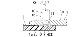
- FIG. 1 is a view for explaining a method for joining a metal member and a resin member according to the first embodiment of the present invention, and is a perspective view in a state in which the metal member and the resin member are being joined together.
- 2A is a sectional view taken along line XX in FIG. 2B is a cross-sectional view taken along line YY in FIG.
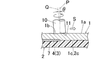
- FIG. 3 is a perspective view for explaining a method of joining the metal member and the resin member to each other as a joining method between the metal member and the resin member according to the second embodiment of the present invention.
- FIG. 1 is a view for explaining a method for joining a metal member and a resin member according to the first embodiment of the present invention, and is a perspective view in a state in which the metal member and the resin member are being joined together.
- 2A is a sectional view taken along line XX in FIG. 2B is a cross-sectional view taken along line YY in FIG.
- FIG. 3 is a perspective view for explaining
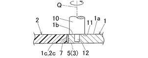
- FIG. 4 is a diagram illustrating a method for joining a metal member and a resin member according to the third embodiment of the present invention, and is a cross-sectional view in a state where the metal member and the resin member are being joined together.
- FIG. 5 is a view for explaining a joining method between a metal member and a resin member according to the fourth embodiment of the present invention, and is a cross-sectional view in a state where the metal member and the resin member are butt-joined.
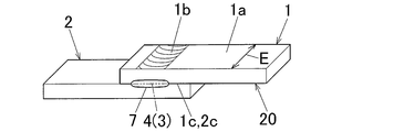
- FIG. 6 is a perspective view of a test piece used in the tensile shear test.
- 1 to 2B are views for explaining a method of joining a metal member and a resin member according to the first embodiment of the present invention.
- 1 is a metal member and 2 is a resin member.
- the thicknesses of the metal member 1 and the resin member 2 are drawn thick in order to facilitate understanding of the present embodiment.
- the metal member 1 has a plate shape (in detail, a flat plate shape).
- the material of the metal member 1 is a metal such as aluminum, aluminum alloy, magnesium alloy, titanium, titanium alloy, copper, copper alloy, iron, steel, or surface-treated steel.
- t is the thickness of the metal member 1.
- the thickness t of the metal member 1 is not limited, but is particularly preferably 0.3 mm or more. The reason is that when the thickness t of the metal member 1 is 0.3 mm or more, the deformation of the metal member 1 can be reliably prevented when the friction energy is applied to the metal member 1. .
- the upper limit of the thickness t of the metal member 1 is not limited and is usually 10 mm.
- Resin member 2 has a plate shape (in detail, a flat plate shape).
- the material of the resin member 2 is a resin such as polyethylene (PE), polypropylene (PP), ethylene-acrylic acid copolymer (EAA), engineering plastic, fluororesin (eg, polytetrafluoroethylene), and ultrahigh molecular weight polyethylene.
- the thickness of the resin member 2 is, for example, 1 to 20 mm.
- the melting point of the resin member 2 is lower than the melting point of the metal member 1.
- the thickness t of the metal member 1 and the thickness of the resin member 2 are equal. However, in this invention, it is not limited to when the thickness t of the metal member 1 and the thickness of the resin member 2 are equal, You may differ.
- the resin member 2 is placed horizontally on a table (not shown) in the atmosphere. And the edge part of the metal member 1 arrange
- a resin layer as an intermediate layer as described in the above prior art is not interposed between the metal member 1 and the resin member 2. That is, the metal member 1 and the resin member 2 are in contact with each other with no resin layer interposed therebetween (that is, directly) and in an overlapping state.
- the rotating tool 10 is used as means for imparting friction energy to the metal member 1.
- the rotary tool 10 is preferably a tool obtained by removing the pin-like probe from a rotary tool as a welding tool used in a friction stir welding method widely applied to joining two metal members. That is, the rotary tool 10 is formed in a cylindrical shape and is configured to be rotationally driven around the axis Q. Further, the rotary tool 10 has a tip surface 11 as a contact portion with the metal member 1.
- the distal end surface 11 of the rotary tool 10 is formed so that the outer peripheral edge thereof exists on a plane perpendicular to the axis Q. In the first embodiment, the distal end surface 11 is perpendicular to the axis Q. Is formed.
- D is the diameter of the tip surface 11 of the rotary tool 10.
- a pin-like probe such as a friction stir welding tool is not provided at the center of the tip surface 11 of the rotary tool 10.
- the rotary tool 10 is made of a heat-resistant material that is harder than the metal member 1 and can withstand frictional heat as frictional energy generated during joining.
- the rotating tool 10 When joining the metal member 1 and the resin member 2, first, the rotating tool 10 is rotated at a high speed. Then, as shown in FIG. 2B, the rotation tool 10 is inclined so that the inclination angle ⁇ of the axis Q of the rotation tool 10 with respect to the normal P of the surface 1a of the metal member 1 satisfies the condition of 0 ° ⁇ ⁇ 5 °. In addition, the metal member 1 and the resin member 2 are in close contact with each other, that is, the overlapping interface 4 (contact interface 3) between the metal member 1 and the resin member 2 is pressurized. The front end surface 11 of the rotary tool 10 is pressed downward from the upper side of the metal member 1 to the surface (upper surface) 1a.
- the portion of the tip end surface 11 of the rotary tool 10 on the inclined side of the rotary tool 10 is slightly embedded in the metal member 1 from the surface 1a, and the tip end surface 11 is inclined with respect to the inclined side of the rotary tool 10.
- the portion on the opposite side slightly floats from the surface 1a of the metal member 1, and frictional heat as frictional energy is generated at the contact portion 1b of the surface 1a of the metal member 1 with the tip surface 11 of the rotary tool 10. .
- the frictional heat is conducted from the contact portion 1 b to the overlapping interface 4 between the metal member 1 and the resin member 2, and the overlapping interface 4 is equal to or higher than the melting point of the resin member 2 due to the frictional heat and the melting point of the metal member 1.
- the resin member 2 is locally melted at the overlapping interface 4.
- the rotating tool 10 is joined along the end of the metal member 1 on the side opposite to the inclined direction. It moves relative to the metal member 1 along the line.
- This relative movement direction is the joining direction S, which is a direction parallel to the surface 1 a of the metal member 1.
- the positions of the metal member 1 and the resin member 2 are fixed, and the rotary tool 10 is moved in the joining direction S.
- reference numeral 7 denotes a joint portion between the metal member 1 and the resin member 2.
- the joint portion 7 is shown by dot hatching so that it can be easily distinguished from other portions.
- the joint 7 is continuously formed in a linear shape along the movement trajectory line of the rotary tool 10 as the rotary tool 10 moves. As a result, the bonding area between the metal member 1 and the resin member 2 increases, that is, the bonding strength increases.
- the tip surface 11 of the rotary tool 10 When the tip surface 11 of the rotary tool 10 reaches a predetermined joining end position, the tip surface 11 of the rotary tool 10 is lifted from the surface 1a of the metal member 1 by raising the rotary tool 10 relative to the metal member 1. Release and release the pressing of the rotary tool 10 against the metal member 1. Thereby, joining of the metal member 1 and the resin member 2 is complete
- the metal member 1 and the resin member 2 are joined at the overlapping interface 4 along the movement trajectory line of the rotary tool 10, so that the lap joint as a joint of the metal member 1 and the resin member 2 is obtained. Is obtained.
- the joining conditions of the joining method of the first embodiment are set according to the types and thicknesses of the materials of the metal member 1 and the resin member 2, and are usually as follows. That is, the diameter D of the distal end surface 11 of the rotary tool 10 is 10 to 30 mm, the rotational speed of the rotary tool 10 is 1000 to 5000 rotations / min, and the joining speed (that is, the moving speed of the rotary tool 10) is 200 to 1000 mm / min. .
- the inclination angle ⁇ of the axis Q of the rotary tool 10 with respect to the normal P of the surface 1a of the metal member 1 needs to satisfy the condition of 0 ° ⁇ ⁇ 5 °. The reason will be described later.
- the inclination angle ⁇ corresponds to “advance angle” in the technical field of friction stir welding.
- a metal oxide film is generally present on the entire surface of the metal member 1. That is, for example, when the material of the metal member 1 is aluminum or an alloy thereof, a film of aluminum oxide (Al 2 O 3 ) is present, and when the material is magnesium or an alloy thereof, magnesium oxide (MgO) is formed. If a film is present, a titanium oxide film is present if it is titanium, a copper oxide film is present if it is copper, and if it is iron or steel, iron is present. An oxide film is present.
- the metal member 1 is preferably one in which at least the contact surface with the resin member 2 of the entire surface is anodized, whereby the contact surface of the metal member 1 with the resin member 2 is improved. The metal oxide film can be positively present, and the metal member 1 and the resin member 2 can be reliably bonded.
- the material of the resin member 2 includes a polymer compound in which carbon and hydrogen are linearly arranged, or a polymer compound in which a part of hydrogen is substituted with another element or atomic group.
- the material of the resin member 2 includes a polymer compound in which a part of hydrogen is substituted with a carboxyl group (COOH) as an atomic group, so that the metal member 1 and the resin member 2 are reliably bonded. Desirable in terms of obtaining.
- the material of the resin member 2 contains almost no carboxyl group and there is almost no carboxyl group on the surface of the resin member 2, if the bonding is performed in the atmosphere, the material of the resin member 2 contains the carboxyl group. It is possible to obtain the same effect as when it is present.
- the metal member 1 and the resin member 2 are brought into contact with each other without interposing the resin layer therebetween, the resin layer is not used. Bonding can be performed easily and inexpensively, and the types of resin members 2 that can be bonded to the metal member 1 are increased. Furthermore, the metal member 1 and the resin member 2 can be joined at an arbitrary location.
- the inclination angle ⁇ of the axis Q of the rotary tool 10 with respect to the normal line P of the surface 1a of the metal member 1 satisfies the condition of 0 ° ⁇ ⁇ 5 °, and thus the following advantages. There is.
- the entire tip surface 11 of the rotary tool 10 is in contact with the surface 1a of the metal member 1, so that the friction energy per unit area necessary for joining is low. Further, when the rotary tool 10 is relatively moved in the joining direction S, a portion of the distal end surface 11 of the rotational tool 10 opposite to the inclined side of the rotational tool 10 (that is, the joining direction S of the distal end surface 11). The surface 1a of the metal member 1 is cut at the front portion), and the frictional heat as frictional energy is insufficient. As a result, the metal member 1 and the resin member 2 cannot be firmly bonded. .
- ⁇ exceeds 5 ° (that is, ⁇ > 5 °)
- the metal member 1 is reduced by excessively pushing the inclined side portion of the rotary tool 10 on the tip surface 11 of the rotary tool 10 into the metal member 1.
- the joint strength decreases due to meat. Therefore, ⁇ needs to satisfy the condition of 0 ° ⁇ ⁇ 5 °, and by doing so, it is possible to ensure the friction energy per unit area necessary for joining, and thereby the metal member 1 and The resin member 2 can be firmly bonded, and further, a decrease in bonding strength due to the thinning of the metal member 1 can be prevented.
- the frictional energy is frictional heat generated by pressing the rotating rotary tool 10 against the surface 1a of the metal member 1, the frictional energy can be locally and easily applied only to a necessary part of the metal member 1. Can be granted.
- the metal member 1 and the resin member 2 can be more securely and firmly joined.
- the rotary tool 10 is tilted and the rotary tool 10 is moved relative to the metal member 1 on the side opposite to the tilt direction in a state where the tip surface 11 is pressed against the surface 1a of the metal member 1.
- the joint 7 between the metal member 1 and the resin member 2 can be formed in a linear shape, whereby the joint strength between the metal member 1 and the resin member 2 can be improved.
- the front side of the surface 1a of the metal member 1 in the joining direction S of the rotary tool 10 is the front side. It is possible to prevent the surface 1a from being cut, and thereby it is possible to reliably apply frictional energy to the metal member 1, and as a result, the metal member 1 and the resin member 2 can be more reliably connected. It can be firmly joined.
- the metal member 1 is anodized at least on the contact surface 1c with the resin member 2.
- the metal member 1 and the resin member 2 can be joined still more firmly.
- the corona discharge treatment means that the members 1 and 2 are passed between an insulated electrode and a dielectric roll, and a high frequency and a high voltage are applied between the electrode and the dielectric roll to cause corona discharge in the atmosphere.
- the corona discharge electrons are irradiated onto the contact surfaces 1c and 2c of the members 1 and 2, radical oxygen and the like are generated along with the generation of the corona discharge.
- the rotary tool 10 is moved relative to the metal member 1.
- the tip end surface 11 of the rotary tool 10 is separated from the surface 1a of the metal member 1 by moving the rotary tool 10 relative to the metal member 1 without moving it in a direction parallel to the surface 1a of the metal member 1.
- the pressing of the rotary tool 10 to the metal member 1 is released.
- the metal member 1 and the resin member 2 are joined in a dotted shape instead of a linear shape at the overlapping interface 4 between them.
- a lap joint of the metal member 1 and the resin member 2 is obtained.
- Other processes in the second embodiment are the same as those in the first embodiment.
- the metal member 1 is an anodized surface on the contact surface 1c with the resin member 2. Furthermore, at least one contact surface (overlapping surface) of the mutual contact surfaces (mutually overlapping surfaces) 1c and 2c between the metal member 1 and the resin member 2 is preliminarily subjected to corona discharge treatment. It is desirable.
- the metal member 1 is thicker than the metal member of the first embodiment.
- a pin-like probe 12 having a diameter smaller than the diameter of the tip surface 11 is integrally projected along the axis Q of the rotary tool 10 at the center of the tip surface 11 of the rotary tool 10 so that the rotary tool 10 rotates. Then, the probe 12 is also configured to rotate integrally with the rotary tool 10.
- the cross-sectional shape of the probe 12 is circular, elliptical, polygonal, or the like.
- the length of the probe 12 is set shorter than the thickness of the metal member 1.
- the front end surface 11 of the rotating rotary tool 10 is pressed against the surface 1a of the metal member 1 in a state where the rotary tool 10 is inclined with respect to the normal line of the surface 1a of the metal member 1.
- the rotating probe 12 is embedded in the metal member 1 when the distal end surface 11 of the rotary tool 10 is pressed against the surface 1 a of the metal member 1.
- the overlapping interface 4 between the metal member 1 and the resin member 2 is higher than the melting point of the resin member 2 and the metal member due to the second frictional heat as the second frictional energy generated by stirring the material of the metal member 1 Heat to a temperature below the melting point of 1.
- the metal member 1 and the resin member 2 are joined at the overlapping interface 4.
- a lap joint of the metal member 1 and the resin member 2 is obtained.
- Other processes in the third embodiment are the same as those in the first embodiment.
- the metal member 1 has been subjected to an anodizing treatment on the contact surface 1 c with the resin member 2. Furthermore, at least one contact surface (overlapping surface) of the mutual contact surfaces (mutually overlapping surfaces) 1c and 2c between the metal member 1 and the resin member 2 is preliminarily subjected to corona discharge treatment. It is desirable.
- FIG. 5 shows a case where the metal member 1 and the resin member 2 are butt-joined.
- the fourth embodiment will be described below with a focus on differences from the first embodiment.
- the metal member 1 and the resin member 2 are placed horizontally on a table (not shown) in the air in the abutted state with no resin layer interposed therebetween. . That is, the end surface of the end portion of the metal member 1 and the end surface of the end portion of the resin member 2 are in direct contact.
- a pin-like probe 12 having a diameter smaller than the diameter of the tip surface 11 is integrally formed along the axis Q of the rotary tool 10 at the center of the tip surface 11 of the rotary tool 10 as in the rotary tool of the third embodiment. Projected. The length of the probe 12 is set shorter than the thickness of the metal member 1.
- the front end surface 11 of the rotating rotary tool 10 is in contact with the butt interface 5 between the metal member 1 and the resin member 2 in a state where the rotary tool 10 is inclined with respect to the normal line of the surface 1 a of the metal member 1 (
- the probe 12 is pressed against the surface 1a of the metal member 1 in the vicinity of the contact interface 3), and the rotating probe 12 is pressed against the surface 1a of the metal member 1 when the tip surface 11 of the rotating tool 10 is pressed against the surface 1a. 1 is embedded.
- the first frictional heat as the first frictional energy generated by pressing the distal end surface 11 of the rotary tool 10 against the metal member 1 and the probe 12 embedded in the metal member 1 are used as a metal member.
- the butt interface 5 between the metal member 1 and the resin member 2 is equal to or higher than the melting point of the resin member 2 and lower than the melting point of the metal member 1 due to the second frictional heat as the second frictional energy generated by stirring the material 1. Heated to a temperature of Thereby, the metal member 1 and the resin member 2 are joined at the butt interface 5. Further, the rotary tool 10 is moved relative to the metal member 1 in parallel with the extending direction of the butt interface 5. Thereby, the junction part 7 is formed in linear form. As a result, a butt joint as a joint between the metal member 1 and the resin member 2 is obtained.
- Other processes of the fourth embodiment are the same as those of the first embodiment.
- the metal member 1 has been subjected to an anodizing treatment on the contact surface 1 c with the resin member 2. Furthermore, at least one contact surface (butting surface) of the mutual contact surfaces (mutual butting surfaces) 1c and 2c between the metal member 1 and the resin member 2 may be subjected to corona discharge treatment before joining. desirable.
- the metal member 1 is thick or the contact interface between the metal member 1 and the resin member 2. 3 (that is, the overlapping interface 4 or the butting interface 5) is far away from the contact portion 1b of the metal member 1 with the rotary tool 10, the contact interface 3 between the metal member 1 and the resin member 2 is surely secured. Heated, and thereby, the metal member 1 and the resin member 2 can be more securely and firmly bonded.
- the length of the probe 12 of the rotary tool 10 depends on the thickness of the metal member 1 and the distance from the contact portion 1b of the metal member 1 with the rotary tool 10 to the contact interface 3 between the metal member 1 and the resin member 2. Is set.
- the rotary tool 10 used in the first and second embodiments is the same as the rotary tool used in the third embodiment, except that the probe 12 protrudes from the distal end surface 11 thereof. good.
- the position of the rotary tool 10 may be fixed, and the metal member 1 and the resin member 2 may be moved to perform joining.
- Examples 1 to 15 and Comparative Examples 1 to 10 A flat metal member 1 made of various materials and a flat resin member 2 made of various materials were prepared.
- the prepared materials of the metal member 1 and the resin member 2 are as shown in the columns “Material of metal member” and “Material of resin member” in Table 1, respectively.
- Metal member material column, the symbol written after the word “aluminum alloy” is an aluminum alloy symbol.
- the aluminum alloy symbol “A2017” is a wrought material, while “AC4C” is a cast material.
- “Anodized” means that the entire surface of the aluminum alloy metal member is anodized by a known method.
- the symbol “AZ31” described after the word “magnet alloy” is a magnesium alloy symbol.
- Aluminum alloy A2017 has a melting point of 640 ° C
- AC4C has a melting point of 610 ° C.
- the melting point of the magnesium alloy AZ31 is 632 ° C.
- all are length 150mm * width 75mm * thickness t1.5mm.
- EAA ethylene-acrylic acid copolymer
- PE polyethylene
- the end in the width direction of the metal member 1 is placed between the metal member 1 and the resin member 2 in the air on the end in the width direction of the resin member 2 arranged horizontally.
- the resin layers were not overlapped, that is, directly overlaid.
- the overlapping width at this time is 50 mm.
- the metal member 1 and the resin member 2 were joined linearly in the superposition interface 4 of both using the rotary tool 10 on the following joining conditions, and, thereby, the metal member 1 And a lap joint of the resin member 2 were obtained.
- Inclination angle ⁇ of rotating tool 10 As described in the “Inclination angle ⁇ ” column in Table 1.
- Rotational speed of rotating tool 10 1000 rotations / min -Joining speed: 400 mm / min -Depth of embedding in the metal member 1 of the front end surface 11 of the rotary tool 10: 0.5 mm.
- ⁇ The maximum tensile shear load per unit joining length is 15 N / mm or more.
- ⁇ The maximum tensile shear load per unit joining length is less than 15 N / mm.
- the term present invention or inventory should not be construed inappropriately as identifying criticality, nor should it be construed as inappropriately applied across all aspects or all embodiments ( That is, it should be understood that the present invention has numerous aspects and embodiments) and should not be construed inappropriately to limit the scope of the present application or the claims.
- the term “embodiment” is also used to describe any aspect, feature, process or step, any combination thereof, and / or any part thereof. It is done. In some examples, various embodiments may include overlapping features.
- the abbreviations “e.g.,” and “NB” may be used, meaning “for example” and “careful”, respectively.
- the present invention can be used for, for example, a joining method between a metal member and a resin member and a joint joint between the metal member and the resin member used in the fields of automobiles, architecture, electrical equipment, aerospace, and the like.
- Metal member 1a Metal member surface 2: Resin member 2a: Resin member surface 3: Contact interface 4: Superposition interface 5: Butting interface 7: Joint portion 10: Rotating tool 11: Tip surface Q of the rotating tool Rotation tool axis P: normal of metal surface
Landscapes
- Engineering & Computer Science (AREA)
- Mechanical Engineering (AREA)
- Physics & Mathematics (AREA)
- Thermal Sciences (AREA)
- Plasma & Fusion (AREA)
- Pressure Welding/Diffusion-Bonding (AREA)
- Lining Or Joining Of Plastics Or The Like (AREA)
Abstract
Un élément de métal (1) et un élément de résine (2) sont amenés en contact sans qu'une couche de résine ne soit interposée entre eux. Un outil de rotation (10), lors de sa rotation, est incliné et poussé contre une surface (1a) de l'élément de métal (1) de sorte que l'angle d'inclinaison θ de l'axe (Q) de l'outil de rotation (10) par rapport à une ligne normale (P) de la surface (1a) de l'élément de métal (1) satisfasse la condition suivante : 0° < θ ≤ 5°. L'élément de métal (1) présente par conséquent une énergie de friction pour la liaison de l'élément de métal (1) et de l'élément de résine (2).
Priority Applications (3)
| Application Number | Priority Date | Filing Date | Title |
|---|---|---|---|
| CN2012800098193A CN103391828A (zh) | 2011-02-21 | 2012-02-17 | 金属构件与树脂构件的接合方法 |
| US14/000,453 US20140064830A1 (en) | 2011-02-21 | 2012-02-17 | Method for bonding metal member and resin member |
| EP12748924.3A EP2679330A4 (fr) | 2011-02-21 | 2012-02-17 | Procédé pour la liaison d'un élément de métal et d'un élément de résine |
Applications Claiming Priority (2)
| Application Number | Priority Date | Filing Date | Title |
|---|---|---|---|
| JP2011035001A JP5817140B2 (ja) | 2011-02-21 | 2011-02-21 | 金属部材と樹脂部材との接合方法 |
| JP2011-035001 | 2011-02-21 |
Publications (1)
| Publication Number | Publication Date |
|---|---|
| WO2012115010A1 true WO2012115010A1 (fr) | 2012-08-30 |
Family
ID=46720791
Family Applications (1)
| Application Number | Title | Priority Date | Filing Date |
|---|---|---|---|
| PCT/JP2012/053839 Ceased WO2012115010A1 (fr) | 2011-02-21 | 2012-02-17 | Procédé pour la liaison d'un élément de métal et d'un élément de résine |
Country Status (5)
| Country | Link |
|---|---|
| US (1) | US20140064830A1 (fr) |
| EP (1) | EP2679330A4 (fr) |
| JP (1) | JP5817140B2 (fr) |
| CN (1) | CN103391828A (fr) |
| WO (1) | WO2012115010A1 (fr) |
Cited By (2)
| Publication number | Priority date | Publication date | Assignee | Title |
|---|---|---|---|---|
| JP2014180776A (ja) * | 2013-03-18 | 2014-09-29 | Uacj Corp | 金属体と樹脂体との接合方法 |
| CN109967858A (zh) * | 2019-03-22 | 2019-07-05 | 哈尔滨工业大学 | 一种适用于金属与聚合物之间的搅拌摩擦焊接方法 |
Families Citing this family (30)
| Publication number | Priority date | Publication date | Assignee | Title |
|---|---|---|---|---|
| JP6102805B2 (ja) * | 2013-03-22 | 2017-03-29 | マツダ株式会社 | 異種部材の接合方法 |
| WO2015046448A1 (fr) * | 2013-09-27 | 2015-04-02 | 株式会社Uacj | Procédé de soudage par malaxage-verrouillage, et article soudé |
| JP6332933B2 (ja) * | 2013-10-01 | 2018-05-30 | 三菱電機株式会社 | 発光ユニットの製造方法 |
| JP6187411B2 (ja) * | 2013-12-26 | 2017-08-30 | トヨタ自動車株式会社 | コイル用導線とコイル用集合導線の製造方法 |
| JP6098527B2 (ja) * | 2014-01-14 | 2017-03-22 | マツダ株式会社 | 金属部材と樹脂部材との接合方法 |
| JP6098526B2 (ja) * | 2014-01-14 | 2017-03-22 | マツダ株式会社 | 金属部材と樹脂部材との接合方法 |
| JP6014879B2 (ja) * | 2014-03-25 | 2016-10-26 | 株式会社栗本鐵工所 | 金属部材と樹脂部材の接合方法 |
| JP6020501B2 (ja) * | 2014-03-27 | 2016-11-02 | トヨタ自動車株式会社 | 接合方法 |
| JP6102813B2 (ja) * | 2014-03-28 | 2017-03-29 | マツダ株式会社 | 金属部材と樹脂部材との接合方法 |
| JP6098564B2 (ja) * | 2014-03-28 | 2017-03-22 | マツダ株式会社 | 金属部材と樹脂部材との接合方法 |
| JP6098565B2 (ja) * | 2014-03-28 | 2017-03-22 | マツダ株式会社 | 金属部材と樹脂部材との接合方法 |
| US10189113B2 (en) * | 2014-04-24 | 2019-01-29 | GM Global Technology Operations LLC | Resistance spot welding method |
| JP6098607B2 (ja) * | 2014-09-30 | 2017-03-22 | マツダ株式会社 | 金属部材と樹脂部材との接合方法 |
| WO2017026238A1 (fr) * | 2015-08-11 | 2017-02-16 | 昭和電工株式会社 | Composition de résine, produit durci de cette dernière, et procédé de soudage par friction-malaxage |
| JP6327280B2 (ja) * | 2016-03-29 | 2018-05-23 | マツダ株式会社 | 金属部材と熱硬化樹脂部材との接合方法およびその方法において使用される金属部材、熱硬化樹脂部材および熱可塑性樹脂シート |
| JP6912316B2 (ja) * | 2017-08-01 | 2021-08-04 | 株式会社日立製作所 | 樹脂金属複合体の解体方法 |
| CN109604811A (zh) * | 2019-01-16 | 2019-04-12 | 扬州大学 | 用于铝合金和尼龙异种材料搅拌摩擦焊接的方法 |
| WO2020183747A1 (fr) | 2019-03-08 | 2020-09-17 | 睦月電機株式会社 | Procédé de production d'un corps moulé en résine synthétique et procédé de production d'un corps assemblé métal-résine |
| CN109807460B (zh) * | 2019-03-20 | 2020-08-25 | 上海交通大学 | 一种通过检测下压力控制金属与高分子焊接的方法 |
| CN109834383B (zh) * | 2019-03-22 | 2020-11-10 | 上海交通大学 | 针对钛合金/超高分子量聚乙烯搭接摩擦点焊的方法与装置 |
| CN110102925B (zh) * | 2019-04-11 | 2020-11-06 | 上海交通大学 | 一种金属与高分子焊接装置及焊接方法 |
| CN110065237A (zh) * | 2019-04-24 | 2019-07-30 | 龙岩学院 | 激光热辅助金属/热塑性塑料摩擦热压连接的装置及方法 |
| US11396139B2 (en) | 2019-05-22 | 2022-07-26 | The Regents Of The University Of Michigan | High-speed polymer-to-metal direct joining system and method |
| CN110653479B (zh) * | 2019-09-26 | 2021-04-27 | 沈阳航空航天大学 | 轻质合金与树脂基复材的搅拌摩擦与超声复合焊接方法 |
| CN110640299B (zh) * | 2019-09-26 | 2021-12-28 | 沈阳航空航天大学 | 一种金属与聚合物板材搅拌摩擦嵌套连接方法 |
| US12318861B2 (en) | 2020-01-02 | 2025-06-03 | The Regents Of The University Of Michigan | Methods of joining dissimilar metals without detrimental intermetallic compounds |
| CN111331244B (zh) * | 2020-03-19 | 2021-06-15 | 尚良仲毅(沈阳)高新科技有限公司 | 一种基于超声振动的搅拌摩擦胶接复合连接方法 |
| US11890788B2 (en) | 2020-05-20 | 2024-02-06 | The Regents Of The University Of Michigan | Methods and process for producing polymer-metal hybrid components bonded by C—O-M bonds |
| CN113441832A (zh) * | 2021-07-26 | 2021-09-28 | 大连交通大学 | 一种预开槽式搅拌摩擦焊方法 |
| JP2023068730A (ja) * | 2021-11-04 | 2023-05-18 | 国立大学法人大阪大学 | 摩擦攪拌接合用ツール及び摩擦攪拌点接合方法 |
Citations (9)
| Publication number | Priority date | Publication date | Assignee | Title |
|---|---|---|---|---|
| JP2003039183A (ja) * | 2001-07-25 | 2003-02-12 | Hitachi Ltd | 摩擦攪拌接合方法及び接合体 |
| JP2003329379A (ja) * | 2002-05-10 | 2003-11-19 | Furukawa Electric Co Ltd:The | ヒートパイプ回路基板 |
| JP2006102803A (ja) * | 2004-10-08 | 2006-04-20 | Japan Science & Technology Agency | 円形内面の接合層形成方法 |
| JP2007098439A (ja) * | 2005-10-05 | 2007-04-19 | Sumitomo Light Metal Ind Ltd | 段付き重合せ材料の摩擦撹拌接合製品 |
| JP2008221321A (ja) * | 2007-03-15 | 2008-09-25 | Mazda Motor Corp | 摩擦点接合方法 |
| JP2009022974A (ja) * | 2007-07-19 | 2009-02-05 | Kosei Aluminum Co Ltd | パイプ部材の内面摩擦圧接法 |
| JP2009241085A (ja) * | 2008-03-28 | 2009-10-22 | Nippon Steel Corp | 接合強度特性に優れたラミネート鋼板の接合方法 |
| JP2009279858A (ja) | 2008-05-23 | 2009-12-03 | Sumitomo Light Metal Ind Ltd | 金属材と樹脂材の接合方法、及び金属材と樹脂材の接合体 |
| JP2010158885A (ja) * | 2008-12-09 | 2010-07-22 | Nippon Light Metal Co Ltd | 樹脂部材と金属部材の接合方法及び液冷ジャケットの製造方法 |
Family Cites Families (15)
| Publication number | Priority date | Publication date | Assignee | Title |
|---|---|---|---|---|
| DE2102020A1 (de) * | 1971-01-16 | 1972-09-21 | Luc J | Klebeverfahren, Einrichtungen zur Durchfuhrung des Verfahrens und Anwen düngen des Verfahrens |
| JPS6024013B2 (ja) * | 1980-01-18 | 1985-06-11 | 東洋製罐株式会社 | 溶接罐及びその製造法 |
| US5862975A (en) * | 1996-03-20 | 1999-01-26 | The Boeing Company | Composite/metal structural joint with welded Z-pins |
| US6299050B1 (en) * | 2000-02-24 | 2001-10-09 | Hitachi, Ltd. | Friction stir welding apparatus and method |
| JP3429475B2 (ja) * | 2000-05-08 | 2003-07-22 | 川崎重工業株式会社 | スポット接合装置およびスポット接合方法 |
| DE60206893T2 (de) * | 2001-03-29 | 2006-07-27 | Mazda Motor Corp. | Drehendes reibungschweissverfahren und vorrichtung |
| JP3751236B2 (ja) * | 2001-08-24 | 2006-03-01 | 株式会社日立製作所 | 摩擦攪拌接合方法 |
| CN1921979A (zh) * | 2004-03-19 | 2007-02-28 | 株式会社日立制作所 | 摩擦搅拌点接合方法以及接合装置 |
| US7347351B2 (en) * | 2004-08-18 | 2008-03-25 | The Boeing Company | Apparatus and system for unitized friction stir welded structures and associated method |
| US20070057015A1 (en) * | 2005-09-09 | 2007-03-15 | Kevin Colligan | Tapered friction stir welding and processing tool |
| JP2007222933A (ja) * | 2006-02-27 | 2007-09-06 | Hitachi Ltd | 摩擦攪拌接合方法 |
| US20090200359A1 (en) * | 2008-02-13 | 2009-08-13 | Gm Global Technology Operations, Inc. | Reducing sheet distortion in friction stir processing |
| US8444040B2 (en) * | 2009-02-11 | 2013-05-21 | Wichita State University | End effector for forming swept friction stir spot welds |
| US8820610B2 (en) * | 2009-10-14 | 2014-09-02 | National University Corporation Gunma University | Using friction stir processing to form foamed metal precursors |
| US20120031249A1 (en) * | 2010-08-06 | 2012-02-09 | Osaka Municipal Technical Research Institute | Method for refining texture of ferrous material, and ferrous material and blade having microscopic texture |
-
2011
- 2011-02-21 JP JP2011035001A patent/JP5817140B2/ja active Active
-
2012
- 2012-02-17 CN CN2012800098193A patent/CN103391828A/zh active Pending
- 2012-02-17 WO PCT/JP2012/053839 patent/WO2012115010A1/fr not_active Ceased
- 2012-02-17 EP EP12748924.3A patent/EP2679330A4/fr not_active Withdrawn
- 2012-02-17 US US14/000,453 patent/US20140064830A1/en not_active Abandoned
Patent Citations (9)
| Publication number | Priority date | Publication date | Assignee | Title |
|---|---|---|---|---|
| JP2003039183A (ja) * | 2001-07-25 | 2003-02-12 | Hitachi Ltd | 摩擦攪拌接合方法及び接合体 |
| JP2003329379A (ja) * | 2002-05-10 | 2003-11-19 | Furukawa Electric Co Ltd:The | ヒートパイプ回路基板 |
| JP2006102803A (ja) * | 2004-10-08 | 2006-04-20 | Japan Science & Technology Agency | 円形内面の接合層形成方法 |
| JP2007098439A (ja) * | 2005-10-05 | 2007-04-19 | Sumitomo Light Metal Ind Ltd | 段付き重合せ材料の摩擦撹拌接合製品 |
| JP2008221321A (ja) * | 2007-03-15 | 2008-09-25 | Mazda Motor Corp | 摩擦点接合方法 |
| JP2009022974A (ja) * | 2007-07-19 | 2009-02-05 | Kosei Aluminum Co Ltd | パイプ部材の内面摩擦圧接法 |
| JP2009241085A (ja) * | 2008-03-28 | 2009-10-22 | Nippon Steel Corp | 接合強度特性に優れたラミネート鋼板の接合方法 |
| JP2009279858A (ja) | 2008-05-23 | 2009-12-03 | Sumitomo Light Metal Ind Ltd | 金属材と樹脂材の接合方法、及び金属材と樹脂材の接合体 |
| JP2010158885A (ja) * | 2008-12-09 | 2010-07-22 | Nippon Light Metal Co Ltd | 樹脂部材と金属部材の接合方法及び液冷ジャケットの製造方法 |
Non-Patent Citations (1)
| Title |
|---|
| See also references of EP2679330A4 |
Cited By (2)
| Publication number | Priority date | Publication date | Assignee | Title |
|---|---|---|---|---|
| JP2014180776A (ja) * | 2013-03-18 | 2014-09-29 | Uacj Corp | 金属体と樹脂体との接合方法 |
| CN109967858A (zh) * | 2019-03-22 | 2019-07-05 | 哈尔滨工业大学 | 一种适用于金属与聚合物之间的搅拌摩擦焊接方法 |
Also Published As
| Publication number | Publication date |
|---|---|
| US20140064830A1 (en) | 2014-03-06 |
| JP5817140B2 (ja) | 2015-11-18 |
| CN103391828A (zh) | 2013-11-13 |
| EP2679330A4 (fr) | 2017-11-15 |
| EP2679330A1 (fr) | 2014-01-01 |
| JP2012170975A (ja) | 2012-09-10 |
Similar Documents
| Publication | Publication Date | Title |
|---|---|---|
| JP5817140B2 (ja) | 金属部材と樹脂部材との接合方法 | |
| Li et al. | Friction self-piercing riveting of aluminum alloy AA6061-T6 to magnesium alloy AZ31B | |
| JP6188789B2 (ja) | 少なくとも2つの層を溶接する方法 | |
| Kimiaki et al. | Effect of silane coupling on the joint characteristics of friction lap joined Al alloy/CFRP | |
| JP2006007266A (ja) | リベットを用いた接合方法 | |
| CN100409995C (zh) | 一种胶焊连接方法 | |
| WO2021095528A1 (fr) | Procédé de liaison en phase solide de matériaux différents, structure liée en phase solide de matériaux différents et dispositif de liaison en phase solide de matériaux différents | |
| KR20190053935A (ko) | 선재적으로 형성된 홀(들)이 없이 적어도 하나의 구성요소를 제2 구성요소에 접합하는 방법 | |
| US9592633B2 (en) | Polymer seaming using diffusion welds | |
| JP4998027B2 (ja) | 摩擦点接合方法 | |
| JP2019136748A (ja) | 抵抗スポット溶接方法 | |
| JP2023013803A (ja) | 摩擦攪拌接合及び抵抗溶接のための接合装置及び接合方法 | |
| JP4228211B2 (ja) | 異種材料の接合構造及び接合方法 | |
| Wang et al. | Hybrid laser technique for joining of polymer and titanium alloy | |
| JP2000301356A (ja) | 金属箔の接合方法並びに超音波溶接具 | |
| JP2004243402A (ja) | 金属箔の接合方法および金属箔繋ぎ装置 | |
| CN110214066B (zh) | 金属薄板的接合方法及金属薄板的接合结构 | |
| JP7425781B2 (ja) | 異種金属の接合方法、および接合装置 | |
| JP6122867B2 (ja) | 軽金属の固相接合のための装置 | |
| JP7365646B2 (ja) | 線形摩擦接合方法及び接合構造体 | |
| JP2014180776A (ja) | 金属体と樹脂体との接合方法 | |
| WO2017169795A1 (fr) | Faisceau de fils et son procédé de fabrication | |
| JP5173760B2 (ja) | 異種金属材料のスポット摩擦攪拌接合方法 | |
| JP2010247194A (ja) | 金属管の接合方法 | |
| Biradar et al. | Joining by Forming of Sheet Metals |
Legal Events
| Date | Code | Title | Description |
|---|---|---|---|
| 121 | Ep: the epo has been informed by wipo that ep was designated in this application |
Ref document number: 12748924 Country of ref document: EP Kind code of ref document: A1 |
|
| NENP | Non-entry into the national phase |
Ref country code: DE |
|
| WWE | Wipo information: entry into national phase |
Ref document number: 2012748924 Country of ref document: EP |
|
| WWE | Wipo information: entry into national phase |
Ref document number: 14000453 Country of ref document: US |