WO2012115061A1 - Dispositif et procédé d'apport de matière pulvérulente - Google Patents
Dispositif et procédé d'apport de matière pulvérulente Download PDFInfo
- Publication number
- WO2012115061A1 WO2012115061A1 PCT/JP2012/054023 JP2012054023W WO2012115061A1 WO 2012115061 A1 WO2012115061 A1 WO 2012115061A1 JP 2012054023 W JP2012054023 W JP 2012054023W WO 2012115061 A1 WO2012115061 A1 WO 2012115061A1
- Authority
- WO
- WIPO (PCT)
- Prior art keywords
- powder
- valve
- pressure
- flow rate
- feed tank
- Prior art date
- Legal status (The legal status is an assumption and is not a legal conclusion. Google has not performed a legal analysis and makes no representation as to the accuracy of the status listed.)
- Ceased
Links
Images

Classifications
-
- B—PERFORMING OPERATIONS; TRANSPORTING
- B65—CONVEYING; PACKING; STORING; HANDLING THIN OR FILAMENTARY MATERIAL
- B65G—TRANSPORT OR STORAGE DEVICES, e.g. CONVEYORS FOR LOADING OR TIPPING, SHOP CONVEYOR SYSTEMS OR PNEUMATIC TUBE CONVEYORS
- B65G53/00—Conveying materials in bulk through troughs, pipes or tubes by floating the materials or by flow of gas, liquid or foam
- B65G53/04—Conveying materials in bulk pneumatically through pipes or tubes; Air slides
- B65G53/16—Gas pressure systems operating with fluidisation of the materials
- B65G53/18—Gas pressure systems operating with fluidisation of the materials through a porous wall
- B65G53/22—Gas pressure systems operating with fluidisation of the materials through a porous wall the systems comprising a reservoir, e.g. a bunker
-
- B—PERFORMING OPERATIONS; TRANSPORTING
- B65—CONVEYING; PACKING; STORING; HANDLING THIN OR FILAMENTARY MATERIAL
- B65G—TRANSPORT OR STORAGE DEVICES, e.g. CONVEYORS FOR LOADING OR TIPPING, SHOP CONVEYOR SYSTEMS OR PNEUMATIC TUBE CONVEYORS
- B65G53/00—Conveying materials in bulk through troughs, pipes or tubes by floating the materials or by flow of gas, liquid or foam
- B65G53/34—Details
- B65G53/66—Use of indicator or control devices, e.g. for controlling gas pressure, for controlling proportions of material and gas, for indicating or preventing jamming of material
Definitions
- the present invention relates to a powder supply apparatus and a powder supply method, and more particularly to a powder supply apparatus and a powder supply method capable of accurately controlling the amount of powder to be supplied in a short time. .
- a combustion furnace that burns pulverized fuel such as pulverized coal supplied from a powder supply device is known as a combustion furnace used in blast furnace facilities, thermal power plants, and the like.
- pulverized fuel is burned while being injected into the combustion furnace together with air.
- Such a combustion method using pulverized coal is widely used for reasons such as high combustibility of the coal itself.
- a gas conveyance type powder supply device for conveying pulverized fuel by a carrier gas.
- the pulverized fuel in the feed tank is supplied to the powder transport pipe and conveyed by the carrier gas in the powder transport pipe.
- Control of the amount of pulverized fuel supplied to the powder transport pipe is controlled by the opening of the powder valve provided at the discharge port at the bottom of the feed tank, or the pressure in the feed tank and the powder transport pipe In some cases, the pressure is controlled by a differential pressure from the internal pressure.
- Patent Document 1 describes such a powder supply apparatus.
- This powder supply device detects an internal pressure control valve for introducing a pressurizing gas into the feed tank, and a differential pressure between the pressure in the powder transport pipe and the pressure in the feed tank, and this differential pressure is determined in advance.
- the differential pressure indicating controller that adjusts the opening of the internal pressure control valve so that it becomes the value of, the powder valve attached to the lower discharge port of the feed tank, and the flow rate of the powder passing through the powder transport pipe
- a powder flow meter for detecting the flow rate, and a powder flow rate indicating controller for inputting a signal from the powder flow meter and adjusting the opening of the powder valve so that the powder flow rate becomes a predetermined value.
- the opening of the internal pressure control valve is adjusted, gas compressed from the outside is introduced into the feed tank, and the pressure in the feed tank rises to a predetermined pressure.
- the pulverized coal is supplied from the feed tank to the powder transport pipe through which the carrier gas flows via the powder valve, and is transported by the carrier gas.
- the pressure in the feed tank and the pressure in the powder transport pipe are detected by a pressure indicator attached to the feed tank and the transport pipe, respectively, and the differential pressure indicating controller has these differential pressures set in advance.
- the pressure in the feed tank is adjusted by adjusting the opening of the internal pressure control valve so as to fall within the range.
- the powder flow rate indicating controller adjusts the opening of the powder valve so that there is no difference from the predetermined flow rate of the pulverized fuel.
- the flow rate of the powder is controlled by making the differential pressure constant and the opening of the powder valve.
- the powder valve is a valve through which powder passes, and the flow rate of the powder can be directly controlled by adjusting the opening of the valve. Therefore, even when the flow rate of the powder changes greatly as at the start of the operation of the powder supply device, it is possible to control the flow rate of the powder in a short time.
- the flow rate of the powder is controlled by the opening of the powder valve as in the powder supply device described in Patent Document 1, the pressure fluctuation in the powder transport pipe, the state of the powder, etc.
- an object of the present invention is to provide a powder supply apparatus and a powder supply method capable of accurately controlling the amount of powder to be supplied in a short time.
- the powder supply apparatus of the present invention is a powder supply apparatus for supplying powder in a feed tank to the outside of the feed tank from a powder transport pipe connected to the feed tank, A powder valve connected to the powder transport pipe, an internal pressure control valve connected to the feed tank for adjusting the pressure in the feed tank, and connected to the powder transport pipe for conveying the powder
- a carrier gas main pipe that introduces a carrier gas for controlling the pressure in the feed tank and the pressure in the carrier gas main pipe by adjusting the pressure in the feed tank by the internal pressure regulating valve.
- the powder valve is adjusted so that the powder flow rate in the transport pipe is constant, and the powder flow valve controls the powder flow rate.
- the internal pressure control valve adjusts the pressure in the feed tank so that the powder flow rate becomes constant while the powder valve is at a constant opening. It is characterized by adjusting the differential pressure.
- the internal pressure regulating valve regulates the pressure in the feed tank, so that the differential pressure between the pressure in the feed tank and the pressure in the carrier gas main pipe is indirectly adjusted. Adjusted. In this state, since the powder flow rate is adjusted by a powder valve that can change the powder flow rate in a short time, even when the powder flow rate changes greatly as at the start of operation of the apparatus. It becomes possible to control the flow rate of the powder in a short time. After the powder flow rate is adjusted by the powder valve, the pressure difference between the pressure in the feed tank and the pressure in the carrier gas main pipe is adjusted by the internal pressure control valve. By adjusting the powder flow rate by adjusting the differential pressure, fine adjustment of the powder flow rate is possible.
- the amount of powder to be supplied can be controlled accurately.
- the correlation between the pressure difference between the pressure in the feed tank and the pressure in the carrier gas main pipe and the powder transport speed in the powder transport pipe is related to the pressure in the feed tank and the powder transport pipe.
- the internal pressure of the combustion furnace are not significantly affected. Therefore, by adjusting the pressure in the feed tank, by directly changing the differential pressure between the pressure in the feed tank and the pressure in the carrier gas main pipe, the powder transport speed in the powder transport pipe is adjusted. be able to.
- the differential pressure one of the pressures (the pressure in the carrier gas main pipe) does not fluctuate so much, so that the control for adjusting the differential pressure can be easily performed.
- powder flow rate means the flow rate of powder in the powder transport pipe.
- a powder flow meter is connected to the powder transport pipe, and after the powder flow rate is adjusted by the powder valve, the internal pressure control valve is The differential pressure is preferably adjusted based on information from the powder flow meter.
- the powder flow rate can be finely adjusted following the slight fluctuation of the powder flow rate. Therefore, the fluctuation width of the supplied powder flow rate can be reduced, and the powder flow rate can be controlled more accurately.
- the powder valve adjusts the powder flow rate based on information from the powder flow meter.
- the powder valve When adjusting the powder valve, the powder valve can be adjusted to be closer to the desired powder flow rate by adjusting the information from the powder flow meter.
- the powder supply apparatus further includes a memory for storing a relationship between the powder flow rate and the opening of the powder valve, and the powder valve is configured to store the powder based on the information in the memory. It is preferable to adjust the body flow rate.
- the powder valve When adjusting the powder valve, the powder valve can be adjusted to be close to the desired powder flow rate in a short time by adjusting the powder valve according to the information in the memory.
- the powder supply apparatus further includes a memory for storing a relationship between the powder flow rate, the opening of the powder valve, and the differential pressure, and the powder valve is configured to store the powder.
- the powder valve adjusts the powder flow rate based on information from the powder flow meter.
- the initial opening of the internal pressure control valve and the powder valve is determined based on the information in the memory. Therefore, the internal pressure control valve and the powder can be quickly adjusted to approach the desired powder flow rate.
- the initial opening of the body valve can be adjusted.
- the internal pressure adjustment valve adjusts the differential pressure so that the powder flow rate becomes constant by adjusting the opening degree. It can be adjusted to be closer to the flow rate.
- the powder supply method of the present invention is a powder supply method for supplying the powder in the feed tank to the outside of the feed tank from the powder transport pipe connected to the feed tank.
- the pressure in the feed tank and the powder transport pipe are connected to convey the powder.
- the pressure inside the carrier pipe is adjusted so that the differential pressure between the pressure inside the carrier gas main pipe to introduce the carrier gas is constant and the powder valve connected to the powder delivery pipe is constant.
- the opening of the powder valve is made constant, and the pressure in the feed tank is adjusted by the internal pressure control valve.
- the pressure difference between the pressure in the feed tank and the pressure in the carrier gas main pipe is adjusted to be constant.
- the powder flow rate is adjusted by the powder valve, so that it is possible to control the powder flow rate in a short time even when the powder flow rate changes greatly as at the start of operation of the device. Become.
- the powder flow rate is adjusted by the powder valve, the differential pressure between the pressure in the feed tank and the pressure in the carrier gas main pipe is adjusted by the internal pressure adjustment valve. Therefore, the amount of powder to be supplied can be controlled accurately.
- the internal pressure adjustment valve After adjusting the powder flow rate by the powder valve in the powder supply method, based on information from a powder flow meter connected to the powder transport pipe, by the internal pressure adjustment valve, It is preferable to adjust the differential pressure.
- the powder flow rate can be finely adjusted following the slight change in the powder flow rate. Therefore, the fluctuation width of the amount of powder to be supplied can be reduced, and the amount of powder to be supplied can be controlled more accurately.
- the powder flow rate when the powder flow rate is adjusted by the powder valve, it is preferable to adjust the powder valve based on information from the powder flow meter. .
- the powder valve When adjusting the powder valve, the powder valve can be adjusted to be closer to the desired powder flow rate by adjusting the information from the powder flow meter.
- the powder flow rate is adjusted by the powder valve, based on information in a memory that stores a relationship between the powder flow rate and the opening of the powder valve.
- the powder valve is preferably adjusted.
- the powder valve When adjusting the powder valve, the powder valve can be adjusted to be close to the desired powder flow rate in a short time by adjusting the powder valve according to the information in the memory.
- the powder flow rate when the powder flow rate is adjusted by the powder valve, the relationship between the powder flow rate, the opening of the powder valve, and the differential pressure. Based on the information stored in the memory, the opening of the internal pressure control valve and the initial opening of the powder valve are adjusted, and then the internal pressure control valve adjusts the differential pressure to be constant. In addition, it is preferable that the powder flow rate is adjusted by the powder valve based on information from the powder flow meter.
- the initial opening of the internal pressure control valve and the powder valve is determined based on the information in the memory. Therefore, the internal pressure control valve and the powder can be quickly adjusted to approach the desired powder flow rate. The initial opening of the valve can be adjusted. Then, since the internal pressure adjusting valve is adjusted based on information from the powder flow meter, it can be adjusted to be closer to the desired powder flow rate.
- a powder supply apparatus and a powder supply method capable of accurately controlling the amount of powder to be supplied in a short time are provided.
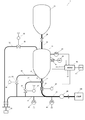
- FIG. 1 is a diagram showing a powder supply apparatus according to an embodiment of the present invention.
- the powder supply apparatus 1 includes a feed tank 11 that supplies a predetermined amount of pulverized coal or other pulverized fuel, and a pressure equalizing tank 12 that stores the pulverized fuel supplied to the feed tank 11.
- An internal pressure gas supply pipe 32 that is connected to the feed tank 11 and conveys the internal pressure gas supplied into the feed tank 11, and an internal pressure adjustment that is provided in the internal pressure gas supply pipe 32 and adjusts the pressure in the feed tank 11.
- a valve 22 a powder transport pipe 31 that is connected to the feed tank 11 and conveys the pulverized fuel supplied from the feed tank 11, and a powder fuel that is connected to the powder transport pipe 31 and is supplied from the feed tank 11
- a powder valve 21 that adjusts the amount of gas, a carrier gas main pipe 33 that is connected to the powder transport pipe 31 and introduces a carrier gas into the powder transport pipe 31, and a powder transport pipe 3
- a powder flowmeter 40 for detecting the flow rate of the pulverized fuel to be conveyed, as the main components.
- the feed tank 11 and the pressure equalizing tank 12 are metal tanks.
- the feed tank 11 is disposed below the pressure equalizing tank 12 and a powder supply pipe 35 connected to the lower part of the pressure equalizing tank 12 is fed to the feed tank 11. It is connected to the upper part of the tank 11. Powdered fuel is supplied from the pressure equalizing tank 12 to the feed tank 11 via the powder supply pipe 35. Further, a powder supply valve 25 is provided in the middle of the powder supply pipe 35, and whether or not powder fuel is supplied from the pressure equalizing tank 12 to the feed tank 11 by opening and closing the powder supply valve 25. Is controlled.
- a load cell 45 is connected to the feed tank 11, and the weight applied from the feed tank 11 to the load cell 45 is continuously detected by the load cell 45.
- a weight indicating controller 46 is connected to the load cell 45, and the weight of the pulverized fuel in the feed tank 11 is continuously measured based on the detection signal output from the load cell. A signal containing information based on weight is output.
- a pressure indicator 48 is connected to the feed tank 11, and the pressure in the feed tank 11 is detected, and a signal including information based on the pressure in the feed tank 11 is output.
- a powder transport pipe 31 is connected to the lower part of the feed tank 11, and the pulverized fuel supplied from the feed tank 11 is introduced into the powder transport pipe 31 from the feed tank 11, as described above. Then, it is conveyed by the powder transport pipe 31.
- the powder valve 21 is connected in the middle of the powder transport pipe 31 below the feed tank 11. Therefore, the pulverized fuel supplied from the feed tank 11 is conveyed by the powder transport pipe 31 through the powder valve 21.
- the powder valve 21 is a rotary type in which a ball valve in which a through-hole having a predetermined inner diameter is formed in a sphere and a set of cylindrical bodies in which cutouts are provided on the side surfaces are arranged so that the side surfaces are in contact with each other. It consists of a control valve.
- the opening of the powder valve 21 By adjusting the opening of the powder valve 21, the amount of pulverized fuel supplied from the feed tank 11 can be controlled to a certain width.
- the powder valve 21 is a valve through which the powder passes, the flow rate of the powder can be directly controlled. For this reason, the powder flow rate can be reduced by adjusting the opening of the powder valve. It is possible to vary greatly with time.
- a powder valve indicator 41 is connected to the powder valve 21, and the powder valve indicator 41 is configured to be able to adjust the opening degree of the powder valve 21. Yes.
- the feed tank 11 is connected to the internal pressure gas supply pipe 32 for supplying the internal pressure gas for adjusting the pressure in the feed tank 11.
- a valve 22 is provided. The supply amount of the internal pressure gas supplied to the feed tank 11 is adjusted by adjusting the opening of the internal pressure adjustment valve 22.
- An internal pressure adjustment valve indicator 42 is connected to the internal pressure adjustment valve 22, and the internal pressure adjustment valve indicator 42 is configured to adjust the opening degree of the internal pressure adjustment valve 22.
- the internal pressure adjusting valve 22 preferably has a function as a discharge valve for releasing the gas in the feed tank 11 to the outside.
- the feed tank 11 is provided with a discharge pipe (not shown), and the discharge pipe is provided with a discharge valve as a second internal pressure adjusting valve, so that unnecessary gas in the feed tank 11 can be discharged to the outside. It may be configured as follows.
- a gas generator 30 is connected to the side opposite to the feed tank 11 side of the internal pressure gas supply pipe 32. Part of the gas output from the gas generator 30 is introduced into the internal pressure gas supply pipe 32 to be used as the internal pressure gas.
- a carrier gas main pipe 33 is connected to the gas generator 30.
- the carrier gas main pipe 33 is a pipe for introducing a carrier gas for carrying the pulverized fuel into the powder transport pipe 31. Therefore, the side opposite to the gas generator 30 side of the carrier gas main pipe 33 is connected to the side opposite to the feed tank 11 side with respect to the powder valve 21 in the powder transport pipe 31 described above.
- the carrier gas introduced from the carrier gas main pipe 33 to the powder transport pipe 31 carries the pulverized fuel introduced from the feed tank 11 through the powder valve 21 to the powder transport pipe 31.
- a pressure indicator 43 is connected to the carrier gas main pipe 33, and the pressure in the carrier gas main pipe 33 is detected, and a signal based on the pressure in the carrier gas main pipe 33 is output.
- the internal pressure gas and the carrier gas are the same gas type.
- the fluidizing gas pipe 34 is branched from the middle of the carrier gas main pipe 33, and the side of the fluidizing gas pipe 34 opposite to the branch side of the carrier gas main pipe 33 is connected to the lower side of the feed tank 11. ing.
- the part where the fluidizing gas pipe 34 is connected to the feed tank 11 is the powder fluidizing part 54.
- a part of the carrier gas flowing in the carrier gas main pipe 33 is introduced into the fluidizing gas pipe 34 as the fluidizing gas, and the fluidizing gas is lowered into the feed tank 11 via the powder fluidizing part 54. It is introduced from the side.
- the fluidized gas and the carrier gas are the same gas type.
- a fluidizing gas valve 24 is provided in the middle of the fluidizing gas pipe 34, and the fluidization gas introduced into the feed tank 11 by adjusting the opening of the fluidizing gas valve 24. The amount of gas is adjusted. Further, a fluidizing gas valve indicator 44 is connected to the fluidizing gas valve 24, and the fluidizing gas valve indicator 44 can adjust the opening degree of the fluidizing gas valve 24. It is configured as follows.
- the refluidizing gas pipe 37 is branched from the middle of the carrier gas main pipe 33 where the fluidizing gas pipe 34 is branched, and the carrier gas main pipe of the refluidizing gas pipe 37 is branched.
- the side opposite to the branch side with respect to 33 is connected between the powder valve 21 and the powder fluidizing portion 54 in the powder transport pipe 31.
- a portion where the refluidizing gas pipe 37 is connected between the powder valve 21 and the powder fluidizing portion 54 is a powder refluidizing portion 57, A refluidizing gas is introduced from the body refluidizing portion 57 into the powder transport pipe 31.
- the powder reflow portion 57 and the powder valve 21 are connected by the powder transport pipe 31, but the powder reflow portion 57 is connected to the powder valve 21. It is preferable that it is directly connected to.
- a part of the carrier gas flowing through the carrier gas main pipe 33 is introduced into the refluidization gas pipe 37 as the refluidization gas, and the refluidization gas passes through the powder refluidization part 57. It is introduced from between the powder valve 21 and the powder fluidizing portion 54.
- the refluidizing gas pipe 37 is branched from the middle of the carrier gas main pipe 33, and in this embodiment, the refluidizing gas and the carrier gas are the same gas type.
- a refluidizing gas valve 27 is provided in the middle of the refluidizing gas pipe 37, and the refluidizing gas introduced by adjusting the opening of the refluidizing gas valve 27. The amount of is adjusted. Further, a reflow gas valve indicator 47 is connected to the reflow gas valve 27, and the reflow gas valve indicator 47 adjusts the opening of the reflow gas valve 27. Configured to be able to.
- a pressure indicator 49 is provided on the downstream side of the part where the pulverized fuel in the powder transport pipe 31 is transported by the carrier gas, that is, the position where the carrier gas main pipe 33 is connected in the powder transport pipe 31. Connected, the pressure in the powder transport pipe 31 is detected, and a signal including information based on the pressure in the powder transport pipe 31 is output.
- a powder flow meter 40 is further provided in the part where the powder fuel in the powder transport pipe 31 is conveyed by the carrier gas, and the flow rate of the powder flowing through the powder transport pipe 31 is detected, and the detected information. Is configured to output a signal including.
- the pressure in the feed tank 11 is made higher than the pressure in the carrier gas main pipe 33, and the pressure in the carrier gas main pipe 33 is higher than the pressure in the powder transport pipe 31. Is also raised.
- the powder supply apparatus 1 is configured to be able to transport pulverized fuel using a differential pressure between these pressures. These pressures are not particularly limited, but are, for example, 2 MPa or more and 4 MPa or less.
- the powder supply apparatus 1 uses the differential pressure to convey the pulverized fuel, the flow rate of the pulverized fuel supplied from the feed tank 11 is opened to the above-described powder valve 21. In addition to the degree, it can also be adjusted by these differential pressures.
- the pressure difference in the feed tank 11 can be adjusted by adjusting the pressure in the feed tank 11 according to the opening of the internal pressure regulating valve 22, and the flow rate of the pulverized fuel supplied from the feed tank 11 can be adjusted. Can be adjusted.
- the powder flow rate can be finely adjusted when adjusting the flow rate of the pulverized fuel.
- the powder supply apparatus 1 includes a control unit 60 connected to the memory 61.
- the control unit 60 is connected to the powder flow meter 40, the pressure indicators 43, 48, 49, and the weight instruction controller 46, and the control unit 60 has the powder output from the powder flow meter 40.
- a signal including information, a signal including information regarding the pressure in the powder transport pipe 31 output from the pressure indicator 49, and a pulverized fuel in the feed tank 11 output from the weight indicating controller 46 A signal or the like including information on the weight of the is input.
- control part 60 uses the signal from the pressure indicator 43,48,49, and the signal output from the weight instruction
- the control unit 60 is connected to a powder valve indicator 41, an internal pressure control valve indicator 42, a fluidizing gas valve indicator 44, and a refluidizing gas valve indicator 47.
- the control unit 60 generates the control for the powder valve indicator 41, the internal pressure control valve indicator 42, the fluidizing gas valve indicator 44, and the refluidizing gas valve indicator 47. It is configured to input a signal.
- the powder valve indicator 41 is configured to adjust the opening of the powder valve 21 based on a control signal from the control unit 60. That is, when the control unit 60 outputs a control signal based on the signal from the powder flow meter 40, the powder valve indicator 41 uses the powder valve based on the information from the powder flow meter 40. Adjust the opening of 21. Therefore, in this case, the powder valve 21 adjusts the powder flow rate by the control signal from the control unit 60 based on the information from the powder flow meter 40. On the other hand, when the control unit 60 outputs a control signal based on the information in the memory 61, the powder valve indicator 41 adjusts the opening degree of the powder valve 21 based on the information in the memory 61. Therefore, in this case, the powder valve 21 adjusts the powder flow rate based on the control signal from the control unit 60 based on the information from the memory 61.
- the internal pressure control valve indicator 42 is configured to be able to adjust the opening degree of the internal pressure control valve 22 based on a signal from the control unit 60.
- the internal pressure control valve indicator 42 indicates that the internal pressure control valve 22 is based on information from the powder flow meter 40. Adjust the opening. Therefore, in this case, the internal pressure adjusting valve 22 adjusts the powder flow rate by the control signal from the control unit 60 based on the information from the powder flow meter 40.
- the internal pressure control valve indicator 42 adjusts the opening degree of the internal pressure control valve 22 based on the information in the memory 61. Therefore, in this case, the internal pressure adjustment valve 22 adjusts the powder flow rate by the control signal from the control unit 60 based on the information from the memory 61.
- the controller 60 uses signals from the pressure indicators 43 and 48 as necessary when generating a signal for adjusting the opening degree of the internal pressure regulating valve 22.
- the fluidizing gas valve indicator 44 is configured to be able to adjust the opening degree of the fluidizing gas valve 24 based on a control signal from the control unit 60. That is, for example, when the control unit 60 outputs a control signal based on a signal from the powder flow meter 40, the fluidizing gas valve indicator 44 is based on information from the powder flow meter 40. The opening degree of the fluidizing gas valve 24 is adjusted. Therefore, in this case, the fluidizing gas valve 24 adjusts the introduction amount of the fluidizing gas by the control signal from the control unit 60 based on the information from the powder flow meter 40.
- the fluidizing gas valve indicator 44 determines the opening degree of the fluidizing gas valve 24 based on the information in the memory 61. Adjust. Therefore, in this case, the fluidizing gas valve 24 adjusts the introduction amount of the fluidizing gas by the control signal from the control unit 60 based on the information from the memory 61.
- the reflow gas valve indicator 47 is configured to be able to adjust the opening degree of the reflow gas valve 27 based on a control signal from the control unit 60. That is, for example, when the control unit 60 outputs a control signal based on the opening degree of the powder valve 21, the reflow gas valve indicator 47 is based on the opening degree of the powder valve 21. Then, the opening degree of the refluidizing gas valve 27 is adjusted. Therefore, in this case, the refluidizing gas valve 27 adjusts the introduction amount of the refluidizing gas by the control signal from the control unit 60 based on the opening degree of the powder valve 21.
- the control signal based on the opening degree of the powder valve 21 output by the control unit 60 is related to the control signal output from the control unit 60 to the powder valve indicator 41 by the control unit 60. Generated.
- the control unit 60 outputs a control signal based on the information in the memory 61
- the reflow gas valve indicator 47 opens the reflow gas valve 27 based on the information in the memory 61. Adjust the degree. Therefore, in this case, the reflow gas valve 27 adjusts the amount of reflow gas introduced by the control signal from the control unit 60 based on the information from the memory 61.
- FIG. 2 is a diagram schematically showing a part of the information in the memory 61.
- the powder flow rate, the opening of the powder valve 21, the pressure in the feed tank 11 and the carrier gas main pipe 33 are shown. It is a figure which shows typically the table which shows the relationship between the differential pressure
- the powder flow rate [kg / h] is specified, the relationship between the opening [%] of the powder valve 21 with respect to the powder flow rate and the differential pressure [MPa] is specified.
- the powder flow rate is 500 [kg / h]
- the opening degree of the powder valve 21 is set to 60 [%]
- the differential pressure is set to 0.03 [MPa].
- a control signal for adjusting the opening degree of the powder valve 21 is generated by the control unit 60, and the powder valve 21 is stored in the memory.
- this control signal is input to the powder valve indicator 41.
- the control unit is based on the information from the pressure indicators 43 and 48 and the information in the memory 61 indicating the pressure difference.
- a control signal for adjusting the opening of the internal pressure adjusting valve 22 is generated.
- the control signal Input to the valve indicator 42.
- the table in the memory 61 is obtained in advance by experiments or the like and recorded in the memory 61.
- the powder transport pipe 31 is directly or indirectly connected to the combustion furnace 100 that burns pulverized fuel and extracts energy.
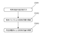
- FIG. 3 is a flowchart showing a method of adjusting the powder flow rate by the powder supply apparatus 1.
- the method for adjusting the powder flow rate by the powder supply apparatus 1 is based on STEP 1 for inputting information on a desired powder flow rate, and a valve for powder based on the inputted powder flow rate information.
- the powder supply valve 25 is opened, and the pulverized fuel is supplied from the pressure equalizing tank 12 to the feed tank 11 through the powder supply pipe 35.
- the fluidizing gas is supplied to the fluidizing gas pipe so that the powdered fuel is supplied from the feed tank 11 to the powder transport pipe 31 through the powder valve 21 by opening the fluidizing gas valve 24.
- 34 is introduced into the feed tank 11 through the powder fluidizing section 54, and the pulverized fuel in the feed tank 11 is fluidized.
- the operator inputs information related to the powder flow rate setting value SV from the input means. In FIG. 1, the input means is omitted.
- the input information is input to the control unit 60, and the control unit 60 refers to the memory 61 and the opening degree of the powder valve 21 corresponding to the information related to the input set value SV of the powder flow rate. And the pressure difference between the pressure in the feed tank 11 and the pressure in the carrier gas main pipe 33 is read out.
- control unit 60 generates a control signal related to the opening degree of the powder valve 21 based on the information in the memory 61, and sends this control signal to the powder valve indicator 41.
- the powder valve indicator 41 adjusts the opening of the powder valve 21 based on a control signal from the control unit 60.
- the initial opening of the powder valve 21 is adjusted based on the information in the memory 61.
- the opening degree of the powder valve 21 is increased and the control from the control unit 60 is performed.
- the opening degree of the refluidizing gas valve 27 is reduced by the signal, and the amount of refluidizing gas introduced is reduced. That is, in this embodiment, the amount of refluidized gas introduced is controlled to be inversely proportional to the opening of the powder valve 21. This is due to the following reason. That is, when the opening of the powder valve 21 is small, clogging with the pulverized fuel is likely to occur, and when the opening of the powder valve 21 is large, the clogging with the pulverized fuel is less likely to occur.
- the introduction amount of the refluidizing gas is determined based on the opening degree of the powder valve, so that an excessive amount of the refluidizing gas can be prevented from being introduced.
- the powder refluidization unit 57 is provided between the powder fluidization unit 54 and the powder valve 21 in the powder transport pipe 31. Even when the pulverized fuel is fluidized by the fluidizing gas, when the powder fuel enters the powder transport pipe 31 from the feed tank 11, the fluidity is lowered and the powder valve 21 is likely to be clogged. However, when the powder is reflowed in the powder transport pipe 31, the powder valve 21 can be prevented from being blocked. Further, as described above, when the powder reflow unit 57 is connected to the powder valve 21, the pulverized fuel is reflowed immediately above the powder valve 21, and the powder reflow unit 57 is used. It is possible to further prevent the valve 21 from being blocked.
- control unit 60 generates a control signal related to the opening degree of the internal pressure control valve 22 based on the information in the memory 61 and the information from the pressure indicators 43 and 48, and uses this control signal as the internal pressure control valve indicator 42. Send to.
- the internal pressure control valve indicator 42 adjusts the initial opening of the internal pressure control valve 22 based on a control signal from the control unit 60. When the opening degree of the internal pressure adjustment valve 22 is adjusted, the differential pressure between the pressure in the feed tank 11 and the pressure in the carrier gas main pipe 33 at an initial stage is set to a predetermined range.
- the control unit 60 Based on the signal from the pressure indicator 48 and the signal from the pressure indicator 43, the differential pressure on the table of the memory 61 and the actual pressure depending on the environment in which the powder supply device 1 is used, the state of the pulverized fuel, etc.
- the control unit 60 again determines the inside of the feed tank 11 based on the information from the pressure indicators 43 and 48.
- a control signal related to the opening of the internal pressure control valve 22 is generated again so that the differential pressure between the pressure and the pressure in the carrier gas main pipe 33 becomes constant, and this control signal is sent to the internal pressure control valve indicator 42. To do.
- the opening degree of the internal pressure adjusting valve 22 is adjusted again, and the differential pressure is adjusted to be constant.
- the differential pressure on the table in the memory 61 is different from the actual differential pressure
- feedback is applied to the internal pressure control valve 22 based on information from the pressure indicators 43 and 48, and the differential pressure is constant.
- the opening degree of the internal pressure control valve 22 is adjusted again. By adjusting in this way, the differential pressure is more accurately adjusted.
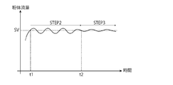
- FIG. 4 is a diagram showing a temporal change in the flow rate of the powder conveyed through the powder transport pipe 31.
- the initial opening of the powder valve 21 is adjusted so that the pressure difference between the pressure in the feed tank 11 and the pressure in the carrier gas main pipe 33 is made constant by the internal pressure control valve 22. Is adjusted to, at t1, the flow rate of the powder conveyed through the powder transport pipe 31 approaches the set value SV.
- the powder valve 21 is adjusted based on the information from the powder flow meter 40 so that the powder flow rate is constant. Specifically, even if the opening degree of the powder valve 21 or the pressure difference between the pressure in the feed tank 11 and the pressure in the carrier gas main pipe 33 is adjusted based on the information in the memory 61, The flow rate of the powder conveyed through the body transport pipe 31 always varies depending on the influence from the combustion furnace 100, the state of the pulverized fuel, and the like. Therefore, the opening degree of the powder valve 21 is adjusted so as to cancel this fluctuation based on the information from the powder flow meter 40, and the powder flow rate is set within a predetermined range.
- the deviation value of the powder flow rate at this time is, for example, 3 to 6%.
- the powder flow rate is adjusted by the powder valve 21 so that the powder flow rate becomes constant. Therefore, even when the powder flow rate changes greatly, the powder flow rate can be controlled in a short time.
- the introduction amount of the refluidizing gas is determined based on the opening degree of the powder valve 21
- the introduction amount of the refluidizing gas is the same as that of the powder valve 21. It is preferably controlled so as to be inversely proportional to the opening.
- the opening degree of the powder valve 21 is made constant. Then, the differential pressure between the pressure in the feed tank 11 and the pressure in the carrier gas main pipe 33 is adjusted. Specifically, based on the information from the powder flow meter 40, the control unit 60 opens the opening of the internal pressure adjustment valve 22 so that the variation in the powder flow rate is canceled and the differential pressure is adjusted. And a control signal is sent to the internal pressure control valve indicator 42.
- the opening of the internal pressure adjusting valve 22 is adjusted by the internal pressure adjusting valve indicator 42 based on the information from the powder flow meter, thereby adjusting the pressure in the feed tank 11, and as a result, The differential pressure between the pressure in the feed tank 11 and the pressure in the carrier gas main pipe 33 is adjusted.
- the internal pressure control valve 22 is set so that the differential pressure between the pressure in the feed tank 11 and the pressure in the carrier gas main pipe 33 becomes large.
- the internal pressure adjustment valve 22 has a differential pressure between the pressure in the feed tank 11 and the pressure in the carrier gas main pipe 33.
- the pressure in the feed tank 11 is adjusted so as to decrease.
- the flow rate of the powder conveyed through the powder transport pipe 31 is adjusted by this differential pressure so as to approach the set value SV.
- the powder flow rate by adjusting the differential pressure can be finely adjusted as described above. Therefore, after t2, the fluctuation range from the set value of the powder flow rate is reduced by adjusting the differential pressure.
- the fluctuation of the powder flow rate at this time varies depending on the type and average particle diameter of the pulverized fuel, and is not particularly limited. However, for example, it is preferably within a range of ⁇ 25%.
- the fluctuation of the powder flow rate is preferably within a range of ⁇ 20%, and more preferably within a range of ⁇ 10%.
- powder having a small fluctuation range is supplied to the combustion furnace 100.
- the internal pressure adjustment valve 22 adjusts the differential pressure between the pressure in the feed tank 11 and the pressure in the carrier gas main pipe 33 to be constant.
- the powder flow rate is adjusted by the powder valve 21, so that the powder flow rate can be reduced in a short time even when the powder flow rate changes greatly as at the start of the operation of the powder supply device 1. Can be controlled.
- the differential pressure between the pressure in the feed tank 11 and the pressure in the carrier gas main pipe 33 is adjusted by the internal pressure adjustment valve 22.
- the powder supply device 1 adjusts the pressure difference between the pressure in the feed tank 11 and the pressure in the carrier gas main pipe 33 based on the information from the powder flow meter 40, thereby adjusting the powder flow rate.
- the powder flow rate can be finely adjusted following a slight change. Therefore, the fluctuation width of the supplied powder flow rate can be reduced, and the powder flow rate can be controlled more accurately.
- the initial opening of the internal pressure control valve 22 and the powder valve 21 is determined based on the information in the memory 61, so that the pressure in the feed tank 11 and the carrier gas main pipe are determined.
- the initial opening degree of the internal pressure adjusting valve 22 and the powder valve 21 can be adjusted in a short time so that the differential pressure from the pressure in the pressure 33 becomes constant.
- the powder valve 21 adjusts the powder flow rate closer to the desired powder flow rate in order to adjust the powder flow rate based on the information from the powder flow meter 40.
- the adjustment of the powder valve in STEP 2 and the adjustment of the differential pressure in STEP 3 were performed based on information from the powder flow meter 40.
- the present invention is not limited to this, and the powder valve may be adjusted in STEP 2 and the differential pressure may be adjusted in STEP 3 based on information from the weight indicating controller 46.
- a signal including information based on the weight of the pulverized fuel output from the weight indicating controller 46 is input to the control unit 60, and the control signal based on the information based on the weight of the pulverized fuel is input to the control unit 60.
- the control signal may be output to the powder valve indicator 41 and the internal pressure control valve indicator 42.
- the opening degree of the powder valve 21 was adjusted based on the information in the memory 61 in the initial stage, and then adjusted based on the information from the weight indicating controller 46.
- the present invention is not limited to this, and the opening degree of the powder valve 21 may be adjusted based on only the information in the memory 61 in STEP2.
- the opening degree of the powder valve 21 may be adjusted only based on information from the weight indicating controller 46. In this case, the opening degree of the powder valve 21 can be accurately adjusted.
- the initial opening degree of the internal pressure control valve 22 is adjusted, and the initial differential pressure between the pressure in the feed tank 11 and the pressure in the carrier gas main pipe 33 is set within a predetermined range. Thereafter, the opening degree of the internal pressure control valve 22 may be constant until STEP 3 is started. Even if comprised in this way, the differential pressure
- the opening degree of the internal pressure adjusting valve 22 is adjusted so that the pressure difference becomes constant from the viewpoint that the differential pressure can be adjusted more accurately.
- the powder valve 21 and the refluidizing section 57 are provided in the middle of the powder transport pipe 31.
- the present invention is not limited to this.
- the powder valve 21 and the reflow unit 57 are directly connected, the powder valve 21 is connected to the end of the powder transport pipe 31, and the reflow unit 57 is located below the feed tank 11. May be connected.
- the powder transport pipe 31 is indirectly connected to the feed tank 11.
- the powder supply apparatus which supplies the powder which is powder fuels, such as pulverized coal, was demonstrated, this invention is not limited to this, The other powder which is not a powder fuel is supplied.
- the present invention can also be applied to a powder supply apparatus.
- the pulverized fuel in the feed tank is fluidized by the fluidizing gas, and the pulverized fuel is re-fluidized in the powder transport pipe 31.
- refluidization is not essential.
- a powder supply apparatus and a powder supply method capable of accurately controlling the amount of powder to be supplied in a short time are provided, and blast furnace equipment and thermal power generation are provided.
- the present invention can be applied to a powder supply device for supplying pulverized fuel to a combustion furnace used in a plant or the like, and other powder supply devices.
Landscapes
- Engineering & Computer Science (AREA)
- Mechanical Engineering (AREA)
- Air Transport Of Granular Materials (AREA)
Abstract
L'invention concerne un dispositif d'apport (1) de matière pulvérulente, qui comporte: une vanne (21) pour matière pulvérulente, ladite vanne étant reliée à une canalisation de transport (31) de matière pulvérulente; une vanne de réglage de pression intérieure (22), reliée à une cuve d'alimentation (11) et qui règle la pression dans la cuve d'alimentation (11); et un tube principal de gaz porteur (33), qui est relié à une canalisation de transport (31) de matière pulvérulente et introduit un gaz porteur en vue du transfert de la matière pulvérulente. La différence de pression entre la pression de la cuve d'alimentation (11) et la pression dans le tube principal de gaz porteur (33) est réglée à une valeur constante, au moyen de la vanne de réglage de pression intérieure (22), ladite vanne (21) réglant à une valeur constante la quantité d'écoulement de matière pulvérulente dans la canalisation de transport (31) de matière pulvérulente; et le degré d'ouverture de la vanne (21) est réglé à une valeur constante après le réglage, au moyen de la vanne (21), de la quantité d'écoulement de matière pulvérulente, la vanne de réglage de pression intérieure (22) réglant la différence de pression afin que la quantité d'écoulement de matière pulvérulente soit constante. Par conséquent, l'invention permet de commander précisément et rapidement la quantité de matière pulvérulente à fournir. L'invention concerne un procédé d'apport de matière pulvérulente qui comporte des caractéristiques identiques.
Applications Claiming Priority (2)
| Application Number | Priority Date | Filing Date | Title |
|---|---|---|---|
| JP2011-035246 | 2011-02-21 | ||
| JP2011035246A JP2012171739A (ja) | 2011-02-21 | 2011-02-21 | 粉体供給装置、及び、粉体供給方法 |
Publications (1)
| Publication Number | Publication Date |
|---|---|
| WO2012115061A1 true WO2012115061A1 (fr) | 2012-08-30 |
Family
ID=46720838
Family Applications (1)
| Application Number | Title | Priority Date | Filing Date |
|---|---|---|---|
| PCT/JP2012/054023 Ceased WO2012115061A1 (fr) | 2011-02-21 | 2012-02-20 | Dispositif et procédé d'apport de matière pulvérulente |
Country Status (2)
| Country | Link |
|---|---|
| JP (1) | JP2012171739A (fr) |
| WO (1) | WO2012115061A1 (fr) |
Cited By (2)
| Publication number | Priority date | Publication date | Assignee | Title |
|---|---|---|---|---|
| CN103043446A (zh) * | 2012-12-27 | 2013-04-17 | 中冶长天国际工程有限责任公司 | 气力输送系统的输气间隔确定方法及系统 |
| CN115121391A (zh) * | 2022-07-12 | 2022-09-30 | 航天科工哈尔滨风华有限公司 | 一种用于电弧增材制造的喷粉装置及方法 |
Families Citing this family (5)
| Publication number | Priority date | Publication date | Assignee | Title |
|---|---|---|---|---|
| KR101371292B1 (ko) * | 2012-10-30 | 2014-03-12 | 고등기술연구원연구조합 | 분체원료 유량 제어장치 |
| JP6107070B2 (ja) * | 2012-11-15 | 2017-04-05 | 新日鐵住金株式会社 | 粉体搬送方法および粉体搬送装置 |
| KR101500457B1 (ko) * | 2013-11-05 | 2015-03-09 | 주식회사 포스코건설 | 전로용 분말원료 투입장치 |
| CN104495389B (zh) * | 2014-12-03 | 2017-09-08 | 福建龙净环保股份有限公司 | 一种物料输送方法 |
| JP6157039B1 (ja) * | 2016-12-09 | 2017-07-05 | ダイヤモンドエンジニアリング株式会社 | 粉体供給装置 |
Citations (4)
| Publication number | Priority date | Publication date | Assignee | Title |
|---|---|---|---|---|
| JPS6283928A (ja) * | 1985-09-19 | 1987-04-17 | Kobe Steel Ltd | 粉体供給制御装置 |
| JPH05147735A (ja) * | 1991-02-18 | 1993-06-15 | Daiyamondo Eng Kk | 粉体流量制御システム |
| JPH06115690A (ja) * | 1991-07-16 | 1994-04-26 | Daiyamondo Eng Kk | 微粉炭排出量制御装置 |
| JP2008038175A (ja) * | 2006-08-03 | 2008-02-21 | Sumitomo Metal Ind Ltd | 粉体吹込み方法 |
-
2011
- 2011-02-21 JP JP2011035246A patent/JP2012171739A/ja not_active Withdrawn
-
2012
- 2012-02-20 WO PCT/JP2012/054023 patent/WO2012115061A1/fr not_active Ceased
Patent Citations (4)
| Publication number | Priority date | Publication date | Assignee | Title |
|---|---|---|---|---|
| JPS6283928A (ja) * | 1985-09-19 | 1987-04-17 | Kobe Steel Ltd | 粉体供給制御装置 |
| JPH05147735A (ja) * | 1991-02-18 | 1993-06-15 | Daiyamondo Eng Kk | 粉体流量制御システム |
| JPH06115690A (ja) * | 1991-07-16 | 1994-04-26 | Daiyamondo Eng Kk | 微粉炭排出量制御装置 |
| JP2008038175A (ja) * | 2006-08-03 | 2008-02-21 | Sumitomo Metal Ind Ltd | 粉体吹込み方法 |
Cited By (3)
| Publication number | Priority date | Publication date | Assignee | Title |
|---|---|---|---|---|
| CN103043446A (zh) * | 2012-12-27 | 2013-04-17 | 中冶长天国际工程有限责任公司 | 气力输送系统的输气间隔确定方法及系统 |
| CN115121391A (zh) * | 2022-07-12 | 2022-09-30 | 航天科工哈尔滨风华有限公司 | 一种用于电弧增材制造的喷粉装置及方法 |
| CN115121391B (zh) * | 2022-07-12 | 2024-01-26 | 航天科工哈尔滨风华有限公司 | 一种用于电弧增材制造的喷粉装置及方法 |
Also Published As
| Publication number | Publication date |
|---|---|
| JP2012171739A (ja) | 2012-09-10 |
Similar Documents
| Publication | Publication Date | Title |
|---|---|---|
| JP5520244B2 (ja) | 粉体供給装置、及び、粉体供給方法 | |
| JP5324729B1 (ja) | 粉体供給装置、及び、粉体供給方法 | |
| JP2012171739A (ja) | 粉体供給装置、及び、粉体供給方法 | |
| RU2461777C2 (ru) | Система вдувания для твердых частиц | |
| JP5255734B1 (ja) | 粉体供給装置、及び、粉体供給方法 | |
| JP5982391B2 (ja) | 粉体供給装置、及び、粉体供給方法 | |
| CN106350119B (zh) | 一种煤气化装置的煤氧输送控制方法及装置 | |
| JP2742001B2 (ja) | 微粉炭吹込み制御方法 | |
| CN105621105B (zh) | 气力输送装置及气力输送装置的辅助管道控制系统 | |
| CN111690442A (zh) | 一种粉煤流量控制方法 | |
| JP6139763B1 (ja) | 粉体並列吹込システム及び粉体並列吹込方法 | |
| JP5738046B2 (ja) | 石炭ガス化石炭移送システム | |
| JP5087879B2 (ja) | 粉体吹込み方法 | |
| JP2014088219A (ja) | 粉体供給装置、及び、粉体供給方法 | |
| JP6906868B2 (ja) | 粉体吹込システム | |
| WO2012115060A1 (fr) | Dispositif et procédé d'apport de matière pulvérulente | |
| US20120257934A1 (en) | Metering system, dense phase conveying system and method for supplying bulk material in powder form | |
| CN102837970B (zh) | 通过粉尘输送管中固定的节流位置均匀地输入粉尘 | |
| JP2014088220A (ja) | 粉体供給装置、及び、粉体供給方法 | |
| EP0116764B1 (fr) | Dispositif pour l'insufflation d'agents d'affinage pulvérulents dans un récipient d'affinage | |
| KR100582164B1 (ko) | 분체 기류 수송량 제어장치 | |
| KR20040011190A (ko) | 미분탄 취입을 위한 피드호퍼의 압력 및 유량 제어장치 | |
| KR101587660B1 (ko) | 미분탄 취입량 제어장치 | |
| JPS586827A (ja) | 高圧粉粒体輸送装置の定流量制御装置 | |
| JP2742000B2 (ja) | 微粉炭吹込み制御方法 |
Legal Events
| Date | Code | Title | Description |
|---|---|---|---|
| 121 | Ep: the epo has been informed by wipo that ep was designated in this application |
Ref document number: 12749537 Country of ref document: EP Kind code of ref document: A1 |
|
| NENP | Non-entry into the national phase |
Ref country code: DE |
|
| 122 | Ep: pct application non-entry in european phase |
Ref document number: 12749537 Country of ref document: EP Kind code of ref document: A1 |