WO2012115111A1 - Stratifié - Google Patents
Stratifié Download PDFInfo
- Publication number
- WO2012115111A1 WO2012115111A1 PCT/JP2012/054151 JP2012054151W WO2012115111A1 WO 2012115111 A1 WO2012115111 A1 WO 2012115111A1 JP 2012054151 W JP2012054151 W JP 2012054151W WO 2012115111 A1 WO2012115111 A1 WO 2012115111A1
- Authority
- WO
- WIPO (PCT)
- Prior art keywords
- layer
- layers
- transparent dielectric
- thickness
- laminate
- Prior art date
- Legal status (The legal status is an assumption and is not a legal conclusion. Google has not performed a legal analysis and makes no representation as to the accuracy of the status listed.)
- Ceased
Links
Images

Classifications
-
- C—CHEMISTRY; METALLURGY
- C03—GLASS; MINERAL OR SLAG WOOL
- C03C—CHEMICAL COMPOSITION OF GLASSES, GLAZES OR VITREOUS ENAMELS; SURFACE TREATMENT OF GLASS; SURFACE TREATMENT OF FIBRES OR FILAMENTS MADE FROM GLASS, MINERALS OR SLAGS; JOINING GLASS TO GLASS OR OTHER MATERIALS
- C03C17/00—Surface treatment of glass, not in the form of fibres or filaments, by coating
- C03C17/34—Surface treatment of glass, not in the form of fibres or filaments, by coating with at least two coatings having different compositions
- C03C17/36—Surface treatment of glass, not in the form of fibres or filaments, by coating with at least two coatings having different compositions at least one coating being a metal
- C03C17/3602—Surface treatment of glass, not in the form of fibres or filaments, by coating with at least two coatings having different compositions at least one coating being a metal the metal being present as a layer
- C03C17/3618—Coatings of type glass/inorganic compound/other inorganic layers, at least one layer being metallic
-
- C—CHEMISTRY; METALLURGY
- C03—GLASS; MINERAL OR SLAG WOOL
- C03C—CHEMICAL COMPOSITION OF GLASSES, GLAZES OR VITREOUS ENAMELS; SURFACE TREATMENT OF GLASS; SURFACE TREATMENT OF FIBRES OR FILAMENTS MADE FROM GLASS, MINERALS OR SLAGS; JOINING GLASS TO GLASS OR OTHER MATERIALS
- C03C17/00—Surface treatment of glass, not in the form of fibres or filaments, by coating
- C03C17/34—Surface treatment of glass, not in the form of fibres or filaments, by coating with at least two coatings having different compositions
- C03C17/36—Surface treatment of glass, not in the form of fibres or filaments, by coating with at least two coatings having different compositions at least one coating being a metal
- C03C17/3602—Surface treatment of glass, not in the form of fibres or filaments, by coating with at least two coatings having different compositions at least one coating being a metal the metal being present as a layer
- C03C17/3639—Multilayers containing at least two functional metal layers
-
- C—CHEMISTRY; METALLURGY
- C03—GLASS; MINERAL OR SLAG WOOL
- C03C—CHEMICAL COMPOSITION OF GLASSES, GLAZES OR VITREOUS ENAMELS; SURFACE TREATMENT OF GLASS; SURFACE TREATMENT OF FIBRES OR FILAMENTS MADE FROM GLASS, MINERALS OR SLAGS; JOINING GLASS TO GLASS OR OTHER MATERIALS
- C03C17/00—Surface treatment of glass, not in the form of fibres or filaments, by coating
- C03C17/34—Surface treatment of glass, not in the form of fibres or filaments, by coating with at least two coatings having different compositions
- C03C17/36—Surface treatment of glass, not in the form of fibres or filaments, by coating with at least two coatings having different compositions at least one coating being a metal
- C03C17/3602—Surface treatment of glass, not in the form of fibres or filaments, by coating with at least two coatings having different compositions at least one coating being a metal the metal being present as a layer
- C03C17/3657—Surface treatment of glass, not in the form of fibres or filaments, by coating with at least two coatings having different compositions at least one coating being a metal the metal being present as a layer the multilayer coating having optical properties
-
- C—CHEMISTRY; METALLURGY
- C03—GLASS; MINERAL OR SLAG WOOL
- C03C—CHEMICAL COMPOSITION OF GLASSES, GLAZES OR VITREOUS ENAMELS; SURFACE TREATMENT OF GLASS; SURFACE TREATMENT OF FIBRES OR FILAMENTS MADE FROM GLASS, MINERALS OR SLAGS; JOINING GLASS TO GLASS OR OTHER MATERIALS
- C03C17/00—Surface treatment of glass, not in the form of fibres or filaments, by coating
- C03C17/34—Surface treatment of glass, not in the form of fibres or filaments, by coating with at least two coatings having different compositions
- C03C17/36—Surface treatment of glass, not in the form of fibres or filaments, by coating with at least two coatings having different compositions at least one coating being a metal
- C03C17/3602—Surface treatment of glass, not in the form of fibres or filaments, by coating with at least two coatings having different compositions at least one coating being a metal the metal being present as a layer
- C03C17/3681—Surface treatment of glass, not in the form of fibres or filaments, by coating with at least two coatings having different compositions at least one coating being a metal the metal being present as a layer the multilayer coating being used in glazing, e.g. windows or windscreens
-
- C—CHEMISTRY; METALLURGY
- C22—METALLURGY; FERROUS OR NON-FERROUS ALLOYS; TREATMENT OF ALLOYS OR NON-FERROUS METALS
- C22C—ALLOYS
- C22C5/00—Alloys based on noble metals
- C22C5/06—Alloys based on silver
Definitions
- the present invention relates to a laminate, and more particularly, to a laminate that is suitably used for multi-layer glass and has an appearance that is neutral or blue when viewed obliquely.
- the Ag thin film has a transparent color, a neutral color (neutral color) and a low resistivity in the visible range.
- An Ag thin film having a thickness of about 10 nm has little absorption in the visible range, and its reflectance is several tens of percent. The reflectance increases as the wavelength becomes longer, and shows a high reflectance in the infrared region.
- the Ag-based multilayer film which has an Ag thin film sandwiched between dielectric thin films and has a low reflectance in the visible region and a high reflectance in the infrared region, shows the same appearance as general glass, and has a low emissivity and a high heat ray reflectance.
- Tempered glass may be used as Low-E glass, for example, window glass for buildings. Further, bent glass is used in the window glass for automobiles. Both tempered glass and bent glass are produced by heat treating a glass plate at a temperature of 550 ° C. to 750 ° C. There are two methods for producing tempered glass or bent glass having an Ag-based multilayer film. One is a method of forming a film on tempered glass or bent glass. The other is a method of forming a film on flat glass, then cutting it into a predetermined size, and performing a heat treatment for strengthening or bending.
- the production cost is lower if the film is formed first, then cut to a predetermined size, and heat treatment for strengthening or bending is performed. It is difficult to stably produce a high-performance Ag-based multilayer film without deterioration after heat treatment, and various know-how is required.
- the development of film materials and film structures has progressed, and Ag-based multilayer films with few defects after heat treatment have been commercialized.
- Low-E glass having two Ag layers is a total film of Ag layers compared to Low-E glass having one Ag layer (Ag1 layer Low-E glass) Thickness can be increased and heat insulation performance is excellent.
- the physical film thickness of an Ag layer (first Ag layer) close to a transparent substrate such as a glass plate and an Ag layer (second Ag layer) far from the transparent substrate is Almost equal.
- the physical thickness of the 1st Ag layer and the 2nd Ag layer intentionally different is also known.
- the physical thickness of the first Ag layer is 50 to 80% of the physical thickness of the second Ag layer (see, for example, Patent Document 1).
- the physical thickness of the first Ag layer is 60 to 70% of the physical thickness of the second Ag layer (see, for example, Patent Document 2).
- the ratio of the physical thickness of the first Ag layer to the physical thickness of the second Ag layer is 1 .05 or more is known.
- the above-mentioned patent document 1 describes the transmittance, the increase in solar factor, and the neutral reflection color, the reflection color when viewed from the vertical and the oblique direction. There are few changes.
- Patent Document 2 the transmittance, the increase of the solar factor, and the neutral reflection color, the change of the reflection color when viewed from the vertical and the angle when viewed from the oblique direction is mentioned.
- Patent Document 3 mentions the coexistence of a neutral reflected color when viewed obliquely, a small solar factor, and a large selectivity.
- the color tone is important from the viewpoint of the design of the design.
- the window glass provided with the Ag-based multilayer film has a low reflectance in the visible range, a neutral reflection color and a transmission color, and an appearance equivalent to that of the base plate glass can be obtained while maintaining high heat shielding properties.
- the appearance when viewed from below that is, viewed from an oblique direction, is important.
- a window glass having an appearance, that is, a reflection color of red, particularly purple is not preferred, and a neutral or blue color similar to the base glass is preferred.
- the window glass for automobiles is attached with an inclination, the appearance when viewed from the front, that is, when viewed from an oblique direction, is important.
- low visible light transmittance is required for the purpose of anti-glare. That is, a low transmittance in the visible region, for example, a visible light transmittance of 50% or less is required in addition to the heat shielding property in the infrared region.
- the primer layer or barrier layer adjacent to the Ag layer is an oxide film of NiCr or Ta.
- the transmittance is 60 to 70%
- the solar factor is 0.32 to 0.42.
- the solar factor is limited to 27.5 or less
- the selectivity is limited to 1.75 or more. Further, the above patent document does not mention visible light transmittance.
- the film thickness ratio of the Ag thin film is described when the glass surface reflection color is kept neutral when viewed obliquely.
- the visible light transmittance is relatively low, for example, when the visible light transmittance is 50% or less, no consideration is given.
- the present invention is a laminate having a two-layered Ag thin film that has a relatively low visible light transmittance, and is preferably a laminate in which the appearance when viewed obliquely is not red or purple but is neutral or blue. The purpose is to provide a body.
- the laminate of the present invention is a laminate in which three transparent dielectric layers and two Ag layers are alternately laminated on a transparent substrate so that the Ag layers are interposed between the transparent dielectric layers.
- the Ag layer is the first Ag layer and the second Ag layer in this order from the transparent substrate side
- the ratio of the physical film thickness of the second Ag layer to the first Ag layer is 1.05 or more
- permeability of a laminated body is 50% or less, It is characterized by the above-mentioned.
- the laminated body of this invention does not ask
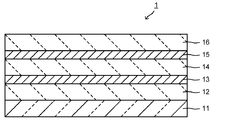
- FIG. 1 is a schematic cross-sectional view showing an embodiment of a laminate according to the present invention.
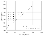
- the schematic sectional drawing which shows the modification of the laminated body of this invention. It is a figure which shows the calculation result of the physical film thickness of the 1st Ag layer and 2nd Ag layer when a * in the CIE-Lab colorimetric method is 1 or less. It is a schematic sectional drawing which shows an example of the multilayer glass using the laminated body of this invention.
- Drawing 1 is a sectional view showing an example of a layered product of an embodiment.
- the laminated body 1 includes a first transparent dielectric layer 12, a first Ag layer 13, a second transparent dielectric layer 14, a second Ag layer 15, and a third transparent dielectric layer on a transparent substrate 11. 16 are laminated in this order, and three transparent dielectric layers 12, 14, 16 and two Ag layers 13, 15 are interposed between the transparent dielectric layers 12, 14, 16, respectively. The Ag layers 13 and 15 are alternately laminated so that each of them is interposed.
- This laminate 1 has a visible light transmittance of 50% or less, and a ratio of the physical thickness of the second Ag layer 15 to the first Ag layer 13 (the physical thickness of the second Ag layer 15). / Physical film thickness of the first Ag layer 13 (hereinafter also simply referred to as a film thickness ratio) is 1.05 or more.
- the appearance (that is, the reflected color) when viewed from an oblique direction with a visible light transmittance of 50% or less is red. It can be neutral or blue rather than purple.
- daytime solar radiation is strong in regions from low latitudes to mid-latitudes, and window glass used in such regions is required to have low visible light transmittance for the purpose of anti-glare.
- the appearance when looked up from below that is, the appearance when looked from diagonally, is important.
- the window glass of an automobile is attached with an inclination, the appearance when viewed from the front, that is, from an oblique direction is important.
- the visible light transmittance is the following 50% neutral color appearance when viewed from an oblique or blue, the a * Specifically in CIE-Lab colorimetric method 1 or less.
- the lower limit of a * is preferably ⁇ 35 or more. Thereby, it can be set as the thing suitable for the window glass of a high-rise building, an outer wall, and the window glass of a motor vehicle.
- the visible light transmittance is not necessarily limited as long as it is 50% or less, but is usually preferably 30% or more, and more preferably 40% or more.
- the transparent substrate 11 is made of, for example, a glass plate such as soda lime glass or non-alkali glass, or a resin film such as polyethylene terephthalate (PET) or polytetrafluoroethylene (PTFE).
- the thickness of the transparent substrate 11 is not particularly limited, but in the case of a glass plate, for example, 1 to 20 mm is preferable, and 2 to 15 mm is more preferable. In the case of a resin film, the thickness is preferably 5 to 500 ⁇ m.
- the term “to” indicating the above numerical range is used in the sense that the numerical values described before and after it are used as the lower limit value and the upper limit value, and unless otherwise specified, “to” is the same in the following specification. Used with meaning.
- a multilayer film having a basic structure of five layers of three transparent dielectric layers and two Ag layers, and further having a light absorber layer and / or a barrier layer in the basic structure of the five layers.
- the transparent substrate itself preferably has a visible light transmittance of 20 to 50%, more preferably 40 to 50%.
- the visible light transmittance is preferably 89 to 92%, and the dominant wavelength is 0.4 to 0.7 ⁇ m. Preferably there is.
- the first to third transparent dielectric layers 12, 14, and 16 are provided to adjust the reflectance and transmittance in the visible range.
- the material used for the transparent dielectric layer include metals such as ZnO, Al-doped ZnO (Al-doped ZnO; the same applies hereinafter), Sn-doped ZnO, SnO 2 , In-doped SnO 2 , TiO 2 , and NbOx. It is made of an oxide or a metal nitride such as Si 3 N 4 or AlN.
- the first to third transparent dielectric layers 12, 14, and 16 may be made of the same material or different materials. Further, each of the first to third transparent dielectric layers 12, 14, 16 may be a single layer or a plurality of layers.
- the refractive indexes of the first to third transparent dielectric layers 12, 14, and 16 are preferably 1.7 to 2.5, more preferably 1.8 to 2.2, and further preferably 1.9 to 2.1. preferable. By using such a refractive index, the interference effect between the first, second, and third transparent dielectric layers 12, 14, and 16 and the first and second Ag layers 13 and 15 can be reduced. It becomes easy to make visible light transmittance 50% or less.
- the refractive index means the refractive index at a wavelength of 550 nm.
- the thickness of the first transparent dielectric layer 12 is preferably 25 to 50 nm, more preferably 30 to 45 nm, and further preferably 35 to 45 nm.
- the thickness of the second transparent dielectric layer 13 is preferably 60 to 100 nm, more preferably 70 to 95 nm, and still more preferably 85 to 95 nm.
- the thickness of the third transparent dielectric layer 16 is preferably 10 to 40 nm, more preferably 10 to 30 nm, and even more preferably 10 to 20 nm.
- the first and second Ag layers 13 and 15 may be made of only Ag, or made of an Ag alloy to which Pd or the like is added.
- the content of metal elements other than Ag is preferably 0.2 to 10% by mass, and more preferably 0.2 to 5% by mass in the entire Ag alloy.
- the film thickness ratio of the two Ag layers of the present invention (that is, the physical film thickness of the second Ag layer 15 / the physical film thickness of the first Ag layer 13) is 1.05 or more.
- the film thickness ratio is preferably 1.09 or more.
- the appearance of the stacked body 1 when viewed from an oblique direction can be made neutral or blue.
- the upper limit of film thickness ratio is not necessarily limited, 1.70 or less are preferable, 1.60 or less are more preferable, and 1.50 or less are more preferable.
- the thickness of the first Ag layer 13 is preferably 5 to 15 nm, more preferably 5 to 13 nm, and even more preferably 5 to 10 nm.
- the thickness of the second Ag layer 15 is preferably 5 to 16 nm, more preferably 5 to 14 nm, and further preferably 5 to 12 nm.
- FIG. 2 is a cross-sectional view showing a modification of the laminate 1.
- the stacked body 1 may include light absorption layers 17 and 18, barrier layers 19 and 21, and a protective layer 22.
- the light absorption layers 17 and 18 are provided in order to assist absorption of visible light and make the visible light transmittance more easily 50% or less.
- the position of the light absorption layers 17 and 18 is not necessarily limited, For example, the surface of the 1st Ag layer 13 or the 2nd Ag layer 15 is mentioned.
- Examples of the light absorption layers 17 and 18 include a layer made of at least one selected from the group consisting of a metal layer, a metal oxide layer, and a metal nitride layer having light absorption in the visible region.
- a metal such as Ti, Nb, NiCr, or the like from a stoichiometry of SiN x or AlN x
- a metal nitride that is light-absorbing in the visible region or from a metal oxide such as CrO x Can be used.
- the thickness thereof is preferably 0.5 to 10 nm, and more preferably 1 to 8 nm.
- the thickness is preferably 1 to 20 nm, and more preferably 2 to 18 nm.
- the barrier layers 19 and 21 are provided to suppress oxidation of the first Ag layer 13, the second Ag layer 15, or the light absorption layers 17 and 18.
- the second transparent dielectric layer 14 and the third transparent dielectric layer 16 are made of a metal oxide such as ZnO, the lower layer is formed at the time of film formation (particularly, in the case of film formation in an oxygen atmosphere).
- the first Ag layer 13, the second Ag layer 15, or the light absorption layers 17 and 18 located in the region may be oxidized.
- the barrier layers 19 and 21 are made of a metal layer, and specifically include those made of Ti, Zn, AlZn, TiZn, NiCr, or the like.
- the thicknesses of the barrier layers 19 and 21 are each preferably in the range of 1 to 10 nm. If it is thinner than 1 nm, it will not function sufficiently as a barrier layer, and if it is thicker than 10 nm, the visible light transmittance of the laminate 1 may be excessively reduced.
- the barrier layers 19 and 21 are formed as metal layers.
- the metal layer formed as a barrier layer may be oxidized to be changed into a metal oxide layer.
- the barrier layers 19 and 21 do not necessarily need to be metal films when the laminate 1 is formed.
- the protective layer 22 is provided to improve the scratch resistance of the surface, and is provided on the outermost surface of the multilayer body 1, generally on the surface of the third transparent dielectric layer 16.
- the protective layer 22 is formed by laminating one or more selected from, for example, a metal nitride layer mainly composed of TiN x , SiN x and the like, and a metal oxide layer mainly composed of TiO 2 or the like. .
- the total thickness of the protective layer 22 is preferably 1 to 20 nm, and more preferably 2 to 10 nm. By setting the thickness of the protective layer 22 to 1 nm or more, the scratch resistance can be effectively improved.
- the visible light transmittance of 30% or more and 50% or less in the laminate of the present invention is a multilayer film having a basic structure of five layers of three transparent dielectric layers and two Ag layers, which is a feature of the present invention. Alternatively, it can be obtained by adjusting the added light absorbing layer or by appropriately selecting the optical characteristics of the transparent substrate to be used.
- the basic film configuration is as follows: transparent substrate 11 (soda lime glass plate, plate thickness 3 mm, visible light transmittance 89%) / first transparent dielectric layer 12 (5AZO, thickness 35 nm) , Refractive index 2.0) / first Ag layer 13 (Ag, thickness 13 nm) / light absorption layer 17 (Ti, thickness 5 nm) / barrier layer 19 (TiO 2 , thickness 3.4 nm, refractive index 2 .5) / second transparent dielectric layer 14 (5AZO, thickness 75 nm, refractive index 2.0) / second Ag layer 15 (Ag, thickness 12 nm) / light absorption layer 18 (Ti, thickness 3 nm) ) / Barrier layer 21 (TiO 2 , thickness 3.4 nm, refractive index 2.5) / third transparent dielectric layer 16 (5AZO
- the film thickness of each layer is sequentially changed within the range of the maximum value (times) and minimum value (times) shown in the table, with the step size shown in the table.
- the film thicknesses of the barrier layers 19 and 21 and the protective layer 22 were fixed, and the film thicknesses were changed only for the other layers.
- the film thickness ranges of the first to third transparent dielectric layers 12, 14, and 16 are 25 to 50 nm, 60 to 90 nm, and 10 to 40 nm, respectively.
- the film thickness ranges of the first and second Ag layers 13 and 15 are 10.4 nm to 15.6 nm and 9.6 nm to 15.6 nm, respectively.
- the film thickness ranges of the first and second light absorption layers 17 and 18 are 1 to 10 nm and 0.6 to 6 nm, respectively.
- the calculation shows that the transparent substrate 11 has a visible light transmittance of 40 to 50% and when viewed obliquely (when the angle from the normal direction (incident angle) is 75 °).
- the definition that a * is 1 or less in the CIE-Lab colorimetric method is generally adopted as a range in which a red reflected color is not confirmed.
- Rf represents the reflection characteristic on the main surface on the multilayer film side, that is, the side opposite to the transparent substrate 11
- Rg represents the reflection characteristic on the main surface on the transparent substrate 11
- T represents the visible light transmission characteristic.
- Y represents reflectance in Rf and Rg, transmittance in T
- a represents a * in the CIE-Lab colorimetric method
- b represents b * in the CIE-Lab colorimetric method.
- diamond-shaped points indicate the physical film thicknesses of the first Ag layer 13 and the second Ag layer 15 from which a solution satisfying the optical characteristics is obtained. Note that each point does not necessarily have only one solution. Usually, the first to third transparent dielectric layers 12, 14, 16 and the light absorption layers 17, 18 have different physical film thicknesses. There exists a solution of A dotted line extending from the lower left to the upper right indicates a position where the film thickness ratio (physical film thickness of the second Ag layer / physical film thickness of the first Ag layer) is 1.05.
- the visible light transmittance is 40 to 50%
- the a * in the CIE-Lab colorimetric method when viewed obliquely is 1
- a limit of visible light transmittance of 40 to 50% is set, but it is not necessarily limited to such a range.
- a * in the CIE-Lab colorimetric method when viewed obliquely can be 1 or less.
- Tables 3 and 4 show examples when the film thickness ratio is less than 1.05 within the above film thickness range.
- This film configuration has a film thickness ratio of 0.81, as shown in Table 4.
- a * exceeds 1 in the CIE-Lab colorimetric method when viewed obliquely, indicating that the appearance is not preferable.
- the laminated body 1 of this invention can be used suitably as one glass plate which comprises a multilayer glass.
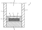
- FIG. 4 shows an example of a multilayer glass 2 using the laminate 1 of the present invention.
- the multilayer glass 2 is, for example, arranged such that the laminated body 1 and the glass plate 3 are arranged at a predetermined interval via the spacer 4.
- a primary sealant 5 seals between the laminate 1 and the spacer 4 and between the glass plate 3 and the spacer 4. Further, the peripheral edge between the laminate 1 and the glass plate 3 is sealed with a secondary sealing material 6.
- the spacer 4 is filled with a desiccant 9 for suppressing condensation in the hollow layer 8 through the through hole 7.
- the hollow layer 8 is filled with argon gas or the like.
- the laminate 1 is disposed on the outdoor side with respect to the glass plate 3 so that the transparent substrate 11 side is on the outdoor side.
- a double-glazed glass 2 since it has the laminated body 1 whose visible light transmittance is 50% or less and the appearance when viewed obliquely is a neutral color or blue, it is a high-rise building, particularly a low latitude. It can be suitably used for window glass and outer walls of high-rise buildings in the area from mid to latitude.
- a laminate having the film configuration shown in Table 5 was manufactured by the sputtering method.
- an Al-added Zn (Al content ratio relative to Zn: 5.0 atomic%) target, 48 mass% Sn, 52 mass% Zn Sn / Zn target, Ti target, and Ag target are contained in the sputtering chamber.
- a cleaned 3 mm thick soda lime glass plate was introduced into an in-line type sputtering apparatus, and evacuated in a load lock chamber until the degree of vacuum was 2 ⁇ 10 ⁇ 6 Torr or less. Subsequently, a glass plate was introduced into the sputtering chamber, and an Al-doped ZnO film (refractive index 2.0) or / and a SnZnOx film (refractive index 2) were sequentially formed as a transparent dielectric layer so as to have the film configuration shown in Table 5.
- 0.0 a pure Ag film as an Ag layer, a Ti film as a barrier layer, a TiNx film as a protective layer, and a TiO 2 film (refractive index of 2.5).
- SnZnOx film, using 48 wt% Sn, 52 wt% Zn targets, the gas flow ratio Ar / O 2 10/9 , was deposited power density of 8.8 W / cm 2.
- the Ag film was formed by using an Ag target, setting the introduced gas to Ar 100%, and the power density to 4.0 W / cm 2 .
- the Ti film was formed using a Ti target with an introduced gas of Ar 100% and a power density of 4.2 W / cm 2 .
- the pressure during film formation was 3 to 5 mTorr.
- the laminate was heat-treated in air at 730 ° C. for 4 minutes. Note that the Ti film serving as the barrier layer does not become all TiO 2 after the Al-doped ZnO film or SnZnOx film serving as the transparent dielectric layer is formed thereon or after the heat treatment, and the lower part remains as Ti metal. It was.
- the a * in the color method was determined.
- the visible light transmittance was measured at a wavelength of 300 to 2500 nm using a Hitachi U-4100 spectrophotometer.
- the reflection color of the obliquely incident transparent substrate side surface (a * in the CIE-Lab colorimetric method) is an oblique incident spectral transmittance using a JASCO Corporation ART-25GT, and the transparent substrate (glass plate) side surface. The reflectance and the film-side surface reflectance were measured and calculated from these measured values.
- the laminate of the present invention has a visible light transmittance as low as 50% or less, and the reflection color when viewed obliquely is neutral or blue, particularly as a Low-E glass plate for buildings, and an automobile. It can be suitably used as a Low-E glass plate for windows and Low-E glass for multilayer glass. It should be noted that the entire content of the specification, claims, drawings and abstract of Japanese Patent Application No. 2011-034195 filed on February 21, 2011 is cited here as the disclosure of the specification of the present invention. Incorporated.
- SYMBOLS 1 Laminated body, 11 ... Transparent base
Landscapes
- Chemical & Material Sciences (AREA)
- Materials Engineering (AREA)
- Engineering & Computer Science (AREA)
- Organic Chemistry (AREA)
- Chemical Kinetics & Catalysis (AREA)
- Geochemistry & Mineralogy (AREA)
- General Chemical & Material Sciences (AREA)
- Life Sciences & Earth Sciences (AREA)
- Mechanical Engineering (AREA)
- Metallurgy (AREA)
- Laminated Bodies (AREA)
- Surface Treatment Of Glass (AREA)
- Physical Vapour Deposition (AREA)
Abstract
La présente invention se rapporte à un stratifié ayant une transmissivité de lumière visible relativement faible et a une couleur neutre ou bleu à la place d'une couleur rouge ou violet lorsque l'on observe l'extérieur du stratifié depuis un angle. L'invention concerne un stratifié (1) formé par la stratification en alternance de trois couches d'une couche diélectrique transparente (12, 14, 16) et de deux couches d'une couche d'Ag (13, 15) sur un substrat transparent de sorte que chaque couche d'Ag (13, 15) soit intercalée entre les couches diélectriques transparentes (12, 14, 16). Lorsque les couches d'Ag (13, 15) sont stratifiées depuis le côté de la base transparente dans l'ordre de couche d'Ag (13) (première couche d'Ag) et de couche d'Ag (15) (seconde couche d'Ag), le rapport de l'épaisseur physique de la seconde couche d'Ag (15) par rapport à la première couche d'Ag (13) est de 1,05 ou plus, et la transmissivité de lumière visible du stratifié (1) est de 50 % ou moins.
Applications Claiming Priority (2)
| Application Number | Priority Date | Filing Date | Title |
|---|---|---|---|
| JP2011-034195 | 2011-02-21 | ||
| JP2011034195A JP2014094448A (ja) | 2011-02-21 | 2011-02-21 | 積層体 |
Publications (1)
| Publication Number | Publication Date |
|---|---|
| WO2012115111A1 true WO2012115111A1 (fr) | 2012-08-30 |
Family
ID=46720888
Family Applications (1)
| Application Number | Title | Priority Date | Filing Date |
|---|---|---|---|
| PCT/JP2012/054151 Ceased WO2012115111A1 (fr) | 2011-02-21 | 2012-02-21 | Stratifié |
Country Status (2)
| Country | Link |
|---|---|
| JP (1) | JP2014094448A (fr) |
| WO (1) | WO2012115111A1 (fr) |
Cited By (6)
| Publication number | Priority date | Publication date | Assignee | Title |
|---|---|---|---|---|
| WO2014109369A1 (fr) * | 2013-01-11 | 2014-07-17 | 旭硝子株式会社 | Corps stratifié et verre multicouche |
| JP2018002564A (ja) * | 2016-07-06 | 2018-01-11 | セントラル硝子株式会社 | グレー色調低放射ガラス |
| CN111517669A (zh) * | 2020-06-09 | 2020-08-11 | 吴江南玻华东工程玻璃有限公司 | 一种高透低反可钢三银低辐射玻璃及其制备方法 |
| CN112499987A (zh) * | 2020-12-10 | 2021-03-16 | 四川南玻节能玻璃有限公司 | 一种红外反射组合膜层及镀膜玻璃 |
| WO2023131766A1 (fr) * | 2022-01-10 | 2023-07-13 | Saint-Gobain Glass France | Vitrage contrôle solaire |
| WO2023131765A1 (fr) * | 2022-01-10 | 2023-07-13 | Saint-Gobain Glass France | Vitrage contrôle solaire |
Families Citing this family (4)
| Publication number | Priority date | Publication date | Assignee | Title |
|---|---|---|---|---|
| KR102118361B1 (ko) * | 2017-04-24 | 2020-06-04 | 주식회사 엘지화학 | 전기변색필름 및 이를 포함하는 전기변색소자 |
| JP2020121889A (ja) * | 2017-05-30 | 2020-08-13 | Agc株式会社 | 波長選択透過性ガラス物品 |
| US11709297B2 (en) | 2018-09-24 | 2023-07-25 | Vitro Flat Glass Llc | Articles coated with coatings containing light absorption materials |
| KR102477303B1 (ko) * | 2020-09-29 | 2022-12-13 | 한국유리공업 주식회사 | 다층 박막 코팅이 구비된 투명 기재 및 그 제조 방법 |
Citations (5)
| Publication number | Priority date | Publication date | Assignee | Title |
|---|---|---|---|---|
| JP2004058592A (ja) * | 2002-07-31 | 2004-02-26 | Asahi Glass Co Ltd | 積層体および構造体 |
| JP2007527353A (ja) * | 2003-07-11 | 2007-09-27 | ピルキントン グループ リミテッド | 太陽調節グレイジング |
| JP2008540320A (ja) * | 2005-05-12 | 2008-11-20 | エージーシー フラット グラス ノース アメリカ,インコーポレイテッド | 低太陽熱利得係数、優れた化学及び機械的特性を有する低放射率コーティング及びその製造方法 |
| JP2009241581A (ja) * | 2008-03-12 | 2009-10-22 | Tokai Rubber Ind Ltd | 透明積層フィルム |
| JP2010195638A (ja) * | 2009-02-26 | 2010-09-09 | Central Glass Co Ltd | 窓用ガラス積層体 |
-
2011
- 2011-02-21 JP JP2011034195A patent/JP2014094448A/ja not_active Withdrawn
-
2012
- 2012-02-21 WO PCT/JP2012/054151 patent/WO2012115111A1/fr not_active Ceased
Patent Citations (5)
| Publication number | Priority date | Publication date | Assignee | Title |
|---|---|---|---|---|
| JP2004058592A (ja) * | 2002-07-31 | 2004-02-26 | Asahi Glass Co Ltd | 積層体および構造体 |
| JP2007527353A (ja) * | 2003-07-11 | 2007-09-27 | ピルキントン グループ リミテッド | 太陽調節グレイジング |
| JP2008540320A (ja) * | 2005-05-12 | 2008-11-20 | エージーシー フラット グラス ノース アメリカ,インコーポレイテッド | 低太陽熱利得係数、優れた化学及び機械的特性を有する低放射率コーティング及びその製造方法 |
| JP2009241581A (ja) * | 2008-03-12 | 2009-10-22 | Tokai Rubber Ind Ltd | 透明積層フィルム |
| JP2010195638A (ja) * | 2009-02-26 | 2010-09-09 | Central Glass Co Ltd | 窓用ガラス積層体 |
Cited By (9)
| Publication number | Priority date | Publication date | Assignee | Title |
|---|---|---|---|---|
| WO2014109369A1 (fr) * | 2013-01-11 | 2014-07-17 | 旭硝子株式会社 | Corps stratifié et verre multicouche |
| JP2018002564A (ja) * | 2016-07-06 | 2018-01-11 | セントラル硝子株式会社 | グレー色調低放射ガラス |
| CN111517669A (zh) * | 2020-06-09 | 2020-08-11 | 吴江南玻华东工程玻璃有限公司 | 一种高透低反可钢三银低辐射玻璃及其制备方法 |
| CN112499987A (zh) * | 2020-12-10 | 2021-03-16 | 四川南玻节能玻璃有限公司 | 一种红外反射组合膜层及镀膜玻璃 |
| CN112499987B (zh) * | 2020-12-10 | 2023-09-26 | 四川南玻节能玻璃有限公司 | 一种红外反射组合膜层及镀膜玻璃 |
| WO2023131766A1 (fr) * | 2022-01-10 | 2023-07-13 | Saint-Gobain Glass France | Vitrage contrôle solaire |
| WO2023131765A1 (fr) * | 2022-01-10 | 2023-07-13 | Saint-Gobain Glass France | Vitrage contrôle solaire |
| FR3131741A1 (fr) * | 2022-01-10 | 2023-07-14 | Saint-Gobain Glass France | Vitrage contrôle solaire |
| FR3131742A1 (fr) * | 2022-01-10 | 2023-07-14 | Saint-Gobain Glass France | Vitrage contrôle solaire |
Also Published As
| Publication number | Publication date |
|---|---|
| JP2014094448A (ja) | 2014-05-22 |
Similar Documents
| Publication | Publication Date | Title |
|---|---|---|
| WO2012115111A1 (fr) | Stratifié | |
| JP6090322B2 (ja) | 積層体 | |
| JP5846203B2 (ja) | 低放射率積層体、および複層ガラス | |
| JP5336739B2 (ja) | 反射防止特性および断熱特性を有する窓ガラス | |
| CN102421720B (zh) | 提供有包括高折射指数层的具有热性质的叠层的基材 | |
| JP5076897B2 (ja) | 赤外線反射ガラス板および車両窓用合わせガラス | |
| CN104619668B (zh) | 提供有吸收层和具有热性质的堆叠体的基材 | |
| RU2747376C2 (ru) | Подложка, снабженная набором, обладающим тепловыми свойствами, ее применение и ее изготовление | |
| KR102346543B1 (ko) | 부분 금속 필름을 포함하는 다층이 구비된 기판, 글레이징 유닛, 용도 및 방법 | |
| JPH07149545A (ja) | 日光及び/又は赤外線に作用する薄い皮膜の積層を備えた透明な基材 | |
| KR20110097939A (ko) | 열 특성을 갖는 다층 스택 및 흡수 층을 구비한 기재 | |
| KR101768257B1 (ko) | 저방사 코팅 및 이를 포함하는 창호용 건축 자재 | |
| KR101914449B1 (ko) | 창호용 기능성 건축 자재 | |
| US11402558B2 (en) | Transparent substrate provided with multi-layered coating and insulation glazing unit including the same | |
| US20240253330A1 (en) | Glazing for preventing bird collisions | |
| WO2014109368A1 (fr) | Film optique multicouche, corps stratifié et verre à double vitrage | |
| KR20170010393A (ko) | 부분 금속 필름을 포함하는 다층이 구비된 기판, 글레이징 유닛, 용도 및 방법 | |
| JP4114429B2 (ja) | 積層体および構造体 | |
| JP7237957B2 (ja) | 熱的特性を有する積層体を備えた基材 | |
| JPH07315889A (ja) | 熱線遮蔽ガラスおよび熱線遮蔽ガラス複合体 | |
| JP2008037667A (ja) | 窓用合わせガラス | |
| JP2006117482A (ja) | 熱線遮蔽ガラス及び熱線遮蔽複層ガラス | |
| KR20170010809A (ko) | 부분 금속 필름을 포함하는 다층이 구비된 기판, 글레이징 유닛, 용도 및 방법 | |
| JP6601419B2 (ja) | 積層膜付きガラス板および複層ガラス | |
| JP2007070146A (ja) | 低放射複層ガラス |
Legal Events
| Date | Code | Title | Description |
|---|---|---|---|
| 121 | Ep: the epo has been informed by wipo that ep was designated in this application |
Ref document number: 12750094 Country of ref document: EP Kind code of ref document: A1 |
|
| NENP | Non-entry into the national phase |
Ref country code: DE |
|
| WWE | Wipo information: entry into national phase |
Ref document number: 1301004604 Country of ref document: TH |
|
| 122 | Ep: pct application non-entry in european phase |
Ref document number: 12750094 Country of ref document: EP Kind code of ref document: A1 |
|
| NENP | Non-entry into the national phase |
Ref country code: JP |