WO2012115123A1 - Structure de couvre-culasse de moteur à combustion interne - Google Patents
Structure de couvre-culasse de moteur à combustion interne Download PDFInfo
- Publication number
- WO2012115123A1 WO2012115123A1 PCT/JP2012/054185 JP2012054185W WO2012115123A1 WO 2012115123 A1 WO2012115123 A1 WO 2012115123A1 JP 2012054185 W JP2012054185 W JP 2012054185W WO 2012115123 A1 WO2012115123 A1 WO 2012115123A1
- Authority
- WO
- WIPO (PCT)
- Prior art keywords
- upper bearing
- outer peripheral
- internal combustion
- combustion engine
- head cover
- Prior art date
- Legal status (The legal status is an assumption and is not a legal conclusion. Google has not performed a legal analysis and makes no representation as to the accuracy of the status listed.)
- Ceased
Links
Images


Classifications
-
- F—MECHANICAL ENGINEERING; LIGHTING; HEATING; WEAPONS; BLASTING
- F02—COMBUSTION ENGINES; HOT-GAS OR COMBUSTION-PRODUCT ENGINE PLANTS
- F02F—CYLINDERS, PISTONS OR CASINGS, FOR COMBUSTION ENGINES; ARRANGEMENTS OF SEALINGS IN COMBUSTION ENGINES
- F02F7/00—Casings, e.g. crankcases
- F02F7/006—Camshaft or pushrod housings
-
- F—MECHANICAL ENGINEERING; LIGHTING; HEATING; WEAPONS; BLASTING
- F01—MACHINES OR ENGINES IN GENERAL; ENGINE PLANTS IN GENERAL; STEAM ENGINES
- F01L—CYCLICALLY OPERATING VALVES FOR MACHINES OR ENGINES
- F01L1/00—Valve-gear or valve arrangements, e.g. lift-valve gear
- F01L1/02—Valve drive
- F01L1/04—Valve drive by means of cams, camshafts, cam discs, eccentrics or the like
- F01L1/047—Camshafts
- F01L2001/0476—Camshaft bearings
Definitions
- the present invention relates to a head cover structure for an internal combustion engine.
- a valve operating mechanism for driving an intake valve and an exhaust valve for opening and closing an intake port and an exhaust port respectively communicating with a combustion chamber is provided on an upper portion of a cylinder head of an internal combustion engine.
- a head cover that covers the valve mechanism is attached to the upper part of the cylinder head.
- an upper member arranged on the upper side of the cam shaft among a plurality of bearing members that are pivotally supported with the cam shaft interposed therebetween is formed integrally with the head cover.
- the upper members are arranged at equal intervals in the axial direction of the cam shaft, and the covering portion that covers between the adjacent upper members is formed in a substantially flat plate shape.
- auxiliary devices such as a cam angle sensor (TDC sensor) for detecting the rotation angle of the cam shaft and a common rail for supplying high-pressure fuel to the fuel injection device are attached to the head cover.
- TDC sensor cam angle sensor
- the detection accuracy of the cam angle sensor may be lowered due to vibration of the head cover.
- an auxiliary device such as a common rail that has been conventionally attached to the cylinder head is attached to a head cover that is relatively less rigid than the cylinder head, vibration and noise may increase. Therefore, further enhancement of the rigidity of the head cover has been desired.
- since there is a demand for a lighter and more compact internal combustion engine there is a limit to improving rigidity by increasing the thickness and size of the head cover.
- the present invention has been made in view of these problems, and it is an object of the present invention to provide a head cover structure for an internal combustion engine that can improve the rigidity of the head cover while suppressing the increase in thickness and size of the head cover.
- a head cover structure for an internal combustion engine according to the present invention is provided along the outer periphery of the covering portion that covers a valve operating mechanism including a cam shaft disposed on the cylinder head from above, and is fastened to the cylinder head.
- a plurality of outer peripheral edge portions integrally provided with the covering portion and the outer peripheral edge portion, and rotatably supporting the camshaft in cooperation with a plurality of lower bearing portions provided on the cylinder head.
- An upper bearing portion, wherein the upper bearing portion is fastened and fixed to the lower bearing portion, and the covering portion is substantially hemispherical between the adjacent upper bearing portions. It has the bulging part which bulges in a shape.
- the rigidity of the covering portion is enhanced by the substantially hemispherical bulging portion.
- the rigidity of a head cover is improved by this bulging part, and it becomes possible to suppress a vibration and a noise.
- the rigidity of the head cover is enhanced by the shape of the bulging portion, it is possible to suppress an increase in thickness and size of the head cover.
- the upper bearing portion has a bearing-side fastening and fixing portion that is fastened and fixed to the lower bearing portion, and the outer peripheral edge portion is provided in the middle of the adjacent upper bearing portion in the cylinder head.
- An outer peripheral side fastening and fixing portion to be fastened and fixed, a first reinforcing rib is provided between the bearing side fastening and fixing portion and the outer peripheral side fastening and fixing portion, and the adjacent upper bearing portion and the first reinforcing rib It is preferable that the bulging portion is provided in a portion surrounded by.
- the first reinforcing rib is provided between the bearing side fastening and fixing portion and the outer periphery side fastening and fixing portion, and the bulging portion is located at a portion surrounded by the adjacent upper bearing portion and the first reinforcing rib. Since it is provided, the rigidity of the head cover can be further increased, and vibration and noise can be further suppressed.
- the lower surface of the bulging part has a configuration in which second reinforcing ribs are extended from the apex of the bulging part toward the bearing side fastening and fixing part and the outer peripheral side fastening and fixing part. .
- the rigidity of the bulging portion can be further increased, the rigidity of the head cover can be further increased, and vibration and noise can be further suppressed.
- the cam shaft includes an intake side cam shaft and an exhaust side cam shaft, and a plurality of the upper bearing portions are arranged along each of the intake side cam shaft and the exhaust side cam shaft, and the intake side cam shaft It is preferable that the bulging portion is provided between at least one of the upper bearing portions of the shaft and between the upper bearing portions of the exhaust cam shaft.
- the rigidity of the head cover can be increased, and vibration and noise can be suppressed.
- a head cover structure for an internal combustion engine that can improve the rigidity of the head cover.
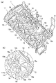
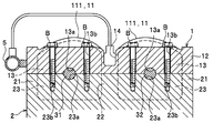
- FIG. 1 It is a perspective view of the head cover structure of the internal combustion engine which concerns on this embodiment. It is a perspective view which shows the state which looked up at the head cover from the bottom, (a) is a general view, (b) is an enlarged view of the A section shown in (a). It is the II sectional view taken on the line shown in FIG. It is the II-II sectional view taken on the line shown in FIG.
- Embodiments of the present invention will be described in detail with reference to FIGS.
- a case where the present invention is applied to a head cover of an automobile engine will be described as an example.
- the same elements are assigned the same numbers, and duplicate descriptions are omitted.
- the direction will be described based on front (F) rear (B) left (L) right (R) shown in FIG.
- the internal combustion engine E is an in-line four-cylinder DOHC (Double Overhead Camshaft) type engine.
- DOHC Double Overhead Camshaft
- a basic structure such as a cylinder block for storing oil and an oil pan for storing oil is provided.
- the internal combustion engine E is placed horizontally so that the cylinder row direction is the left-right direction with respect to the vehicle, and is configured to intake from the rear and exhaust from the front.
- the cylinder head 2 is a member constituting a combustion chamber, an intake port, and an exhaust port (not shown).
- the cylinder head 2 has an intake valve and an exhaust valve (not shown) that open and close the intake port and the exhaust port, respectively, and a valve operating mechanism that drives the intake valve and the exhaust valve above the cylinder head 2. 3 is installed. Further, a transmission mechanism 4 for transmitting the rotation of the crank to the valve operating mechanism 3 is provided at the side of the cylinder head 2 (more specifically, the internal combustion engine E).
- the cylinder head 2 has an outer peripheral wall 21 that rises in a frame shape along the outer peripheral edge of the upper surface 2a, and a central wall 22 that rises from the center in the front-rear direction of the upper surface 2a.
- the cylinder head 2 includes a plurality of lower bearing portions 23 for supporting cam shafts 31 and 32 of the valve operating mechanism 3 between the outer peripheral wall 21 and the central wall 22.
- the lower bearing portion 23 is a wall-like portion extending in the front-rear direction, and has a semicircular recess 23 a at the center of the upper surface thereof.
- the lower bearing portion 23 is provided at a position corresponding to the upper bearing portion 13 provided in the head cover 1 described later.
- the valve operating mechanism 3 includes a pair of cam shafts 31 and 32 arranged in parallel to each other along the cylinder row direction, and a plurality of cams 33 (see FIG. 4) fixed to the cam shaft 31 and the cam shaft 32, respectively. ,have.
- the cam shaft 31 is an intake side cam shaft for opening and closing the intake valve
- the cam shaft 32 is an exhaust side cam shaft for opening and closing the exhaust valve.
- the head cover 1 is an aluminum alloy member that is attached to the upper part of the cylinder head 2 and covers the valve mechanism 3.
- the head cover 1 includes a covering portion 11 that covers the valve operating mechanism 3, an outer peripheral edge portion 12 that forms the outer peripheral edge of the head cover 1, an upper bearing portion 13 that supports the cam shafts 31 and 32 of the valve operating mechanism 3, It has mainly.
- a concave groove portion 14 for installing a fuel injection device extends in the left-right direction at the center portion of the head cover 1 in the front-rear direction.
- the outer peripheral edge portion 12 is a frame-shaped portion provided on the outer peripheral edge of the covering portion 11.
- the outer peripheral edge 12 is installed on an outer peripheral wall 21 provided on the upper surface of the cylinder head 2.
- the outer peripheral edge portion 12 has a plurality of bolt insertion holes 12a for inserting bolts B as fastening members, and some of them are provided between the adjacent upper bearing portions 13.
- the bolt insertion hole 12a corresponds to an “outer periphery side fastening portion” in the claims.
- a bolt fastening hole 21a for fastening the bolt B is formed in the outer peripheral wall 21 of the cylinder head 2 at a position corresponding to the bolt insertion hole 12a (see FIG. 4).
- the upper bearing portion 13 is a portion that rotatably holds the cam shafts 31 and 32 of the valve operating mechanism 3 in cooperation with a plurality of lower bearing portions 23 provided in the cylinder head 2.
- the upper bearing portion 13 is a wall-like portion extending in the front-rear direction, and is provided apart from each other in the left-right direction between the outer peripheral edge portion 12 and the recessed groove portion 14.
- the upper bearing portion 13 is disposed on both the left and right sides of each cylinder.
- the upper bearing portion 13c disposed on the left side of the leftmost cylinder also serves as the left end portion 12b (see FIG. 2A) of the outer peripheral edge portion 12.
- a semicircular recess 13 a is provided at the center of the lower surface of the upper bearing portion 13 in the front-rear direction.
- the concave portion 13a provided in the upper bearing portion 13 and the concave portion 23a provided in the lower bearing portion 23 constitute a bearing portion that rotatably supports the cam shafts 31 and 32, respectively.
- Bolt insertion holes 13b for inserting bolts B as fastening members are provided on both front and rear sides of the recess 13a.
- the bolt insertion hole 13b corresponds to a “bearing side fastening and fixing portion” in the claims.
- a bolt fastening hole 23b for fastening the bolt B is formed in the lower bearing portion 23 of the cylinder head 2 at a position corresponding to the bolt insertion hole 13b.
- coated part 11 is a thin-plate-shaped site
- the covering portion 11 has a bulging portion 111 that bulges substantially hemispherically toward the upper side between the adjacent upper bearing portions 13. Further, as shown in FIG. 1, the covering portion 11 has a first reinforcing rib 15 for reinforcing the bulging portion 111.
- the first reinforcing rib 15 extends so as to rise between the bolt insertion hole 12a of the outer peripheral edge portion 12 provided between the adjacent upper bearing portions 13 and the bolt insertion hole 13b of the upper bearing portion 13. Yes.
- substantially hemispherical includes a hemispherical shape and a shape that can be regarded as equivalent to a hemispherical shape (so-called dome shape or the like).
- the lower surface of the bulging portion 111 is provided between the bolt insertion hole 13 b of the upper bearing portion 13 and the adjacent upper bearing portions 13 from the apex 111 a of the bulging portion 111.
- the second reinforcing ribs 16 extend radially toward the bolt insertion holes 12a of the outer peripheral edge portion 12 and the concave groove portion 14.
- the second reinforcing ribs 16 are arranged substantially symmetrically with the vertex 111a as the center. Thereby, since the bulging part 111 is reinforced uniformly, a vibration and a noise can be reduced. Further, the second reinforcing rib 16 is curved so as to be convex upward along the lower surface of the bulging portion 111 in order to avoid interference with the cam 33 (see FIG. 4).
- a common rail 5 for supplying high-pressure fuel to a fuel injection device (not shown) is attached to the rear end portion of the head cover 1.
- a cam angle sensor 6 that detects the rotation angle of the cam shaft 32 is attached to the upper surface of the head cover 1.
- a negative pressure pump 7 that supplies hydraulic pressure to a variable valve timing mechanism (not shown) of the valve operating mechanism 3 is attached to the left end of the head cover 1.
- An engine hanger 8 for holding the internal combustion engine E on a body frame (not shown) is attached to the left side of the front end portion of the head cover 1.
- an opening 9 for discharging blow-by gas to a gas-liquid separation chamber (not shown) provided separately from the head cover 1 is provided on the upper surface of the right end portion of the head cover 1.
- the head cover structure of the internal combustion engine according to the present embodiment is basically configured as described above. Next, the function and effect will be described.
- the upper bearing portion 13 that pivotally supports the cam shafts 31 and 32 is provided integrally with the head cover 1, and is substantially between adjacent upper bearing portions 13. Since the bulging portion 111 bulging in a hemispherical shape is formed, the rigidity of the covering portion 11 is enhanced by the substantially hemispherical bulging portion 111. Therefore, the rigidity of the head cover 1 can be improved as a whole while suppressing the increase in thickness and size of the head cover 1, and vibration and noise can be suppressed.
- the first reinforcing rib 15 is provided between the bolt insertion hole 12 a of the outer peripheral edge portion 12 provided between the adjacent upper bearing portions 13 and the bolt insertion hole 13 b of the upper bearing portion 13.
- the bulging portion 111 is provided at a portion surrounded by the adjacent upper bearing portion 13 and the first reinforcing rib 15, the rigidity of the head cover 1 can be further enhanced, and vibration and noise can be suppressed. become.
- the bolt of the outer peripheral edge portion 12 provided between the bolt insertion hole 13 b of the upper bearing portion 13 and the adjacent upper bearing portions 13 from the apex 111 a of the bulging portion 111. Since the second reinforcing ribs 16 extend radially toward the insertion hole 12a and the recessed groove portion 14, the rigidity of the bulging portion 111 can be further increased, and vibration and noise can be further suppressed. Can do.
- the bulging portion 111 can be uniformly reinforced, and vibration and noise can be reduced.
- the rigidity of the head cover 1 is enhanced as a whole by the bulging portion 111, auxiliary devices such as the common rail 5, the cam angle sensor 6, the negative pressure pump 7, and the engine hanger 8 can be attached to the head cover 1. it can. Therefore, the degree of freedom in the layout of the internal combustion engine E can be improved.
- the present invention is applied to a so-called DOHC type internal combustion engine E.
- DOHC Double Overhead Camshaft
- the present invention is not limited to this, and may be applied to an SOHC (Single Overhead Camshaft) type internal combustion engine, for example.
- the gas-liquid separation chamber is provided separately from the head cover 1, but the gas-liquid separation chamber may be provided inside the head cover 1.
- the head cover 1 can be reduced in weight and size by providing, for example, a resin-made gas-liquid separation chamber that communicates with the opening 9 separately from the head cover 1.
- the bulging part 111 was formed between all the adjacent upper bearing parts 13, this invention is not limited to this, A plurality of adjacent upper bearing parts 13 The bulging part 111 should just be formed in the location where reinforcement is required among them.
Landscapes
- Engineering & Computer Science (AREA)
- Chemical & Material Sciences (AREA)
- Combustion & Propulsion (AREA)
- Mechanical Engineering (AREA)
- General Engineering & Computer Science (AREA)
- Cylinder Crankcases Of Internal Combustion Engines (AREA)
- Valve-Gear Or Valve Arrangements (AREA)
Abstract
La présente invention porte sur les moteurs à combustion interne. Le but de la présente invention consiste à créer une structure de couvre-culasse de moteur à combustion interne apte à supprimer l'accroissement de l'épaisseur de paroi et la dimension d'un couvre-culasse et de renforcer la rigidité du couvre-culasse. Une structure de couvre-culasse de moteur à combustion interne (E) comporte les éléments suivants : une partie de recouvrement (11) qui est disposée sur une culasse (2) et qui recouvre, par le dessus, une commande (3) des soupapes qui comprend elle-même des arbres à cames (31, 32) ; une partie de bord périphérique extérieur (12) qui est disposée le long du bord périphérique extérieur de la partie de recouvrement (11) et est fixée à la culasse (2) ; et une pluralité de parties de portée supérieures (13) qui sont disposées en une seule pièce avec la partie de recouvrement (11) et avec la partie de bord périphérique extérieur (12), et qui tiennent les arbres à cames (31, 32) de façon rotative en coopération avec une pluralité de parties de palier inférieures (23) situées sur la culasse (2). La structure de couvre-culasse de moteur à combustion interne (E) est caractérisée par les éléments suivants : les parties de palier supérieures (13) sont immobilisées et fixées aux parties de palier inférieures (23) ; et la partie de recouvrement (11) possède une partie de prolongement (111) qui s'étend dans une forme sensiblement hémisphérique entre les parties de palier supérieures adjacentes (13).
Priority Applications (3)
| Application Number | Priority Date | Filing Date | Title |
|---|---|---|---|
| CN201280010029.7A CN103403332B (zh) | 2011-02-22 | 2012-02-22 | 内燃机的气缸盖罩结构 |
| EP12749912.7A EP2679792B1 (fr) | 2011-02-22 | 2012-02-22 | Structure de couvre-culasse de moteur à combustion interne |
| JP2013501082A JP5581438B2 (ja) | 2011-02-22 | 2012-02-22 | 内燃機関のヘッドカバー構造 |
Applications Claiming Priority (2)
| Application Number | Priority Date | Filing Date | Title |
|---|---|---|---|
| JP2011-035549 | 2011-02-22 | ||
| JP2011035549 | 2011-02-22 |
Publications (1)
| Publication Number | Publication Date |
|---|---|
| WO2012115123A1 true WO2012115123A1 (fr) | 2012-08-30 |
Family
ID=46720899
Family Applications (1)
| Application Number | Title | Priority Date | Filing Date |
|---|---|---|---|
| PCT/JP2012/054185 Ceased WO2012115123A1 (fr) | 2011-02-22 | 2012-02-22 | Structure de couvre-culasse de moteur à combustion interne |
Country Status (4)
| Country | Link |
|---|---|
| EP (1) | EP2679792B1 (fr) |
| JP (1) | JP5581438B2 (fr) |
| CN (1) | CN103403332B (fr) |
| WO (1) | WO2012115123A1 (fr) |
Cited By (4)
| Publication number | Priority date | Publication date | Assignee | Title |
|---|---|---|---|---|
| JP2015124730A (ja) * | 2013-12-27 | 2015-07-06 | 株式会社マーレ フィルターシステムズ | カバー部材 |
| US20220275770A1 (en) * | 2021-02-26 | 2022-09-01 | Mahle International Gmbh | Cylinder head cover |
| JP2023066037A (ja) * | 2021-10-28 | 2023-05-15 | マツダ株式会社 | エンジンの上部構造 |
| US20240360776A1 (en) * | 2023-04-28 | 2024-10-31 | Cummins Inc. | Camshaft carrier for supporting a camshaft, an engine system, and a method of assembly |
Families Citing this family (2)
| Publication number | Priority date | Publication date | Assignee | Title |
|---|---|---|---|---|
| FR3026789B1 (fr) * | 2014-10-02 | 2016-11-04 | Renault Sa | Couvre-culasse de moteur a combustion interne |
| JP6631176B2 (ja) * | 2015-11-09 | 2020-01-15 | いすゞ自動車株式会社 | 内燃機関のシリンダヘッド構造及び内燃機関 |
Citations (4)
| Publication number | Priority date | Publication date | Assignee | Title |
|---|---|---|---|---|
| JPH0560014A (ja) * | 1991-09-03 | 1993-03-09 | Yamaha Motor Co Ltd | 内燃機関のシリンダヘツドカバー構造 |
| JP2007192104A (ja) * | 2006-01-19 | 2007-08-02 | Toyota Motor Corp | 内燃機関のカムシャフト支持構造 |
| JP2008057406A (ja) * | 2006-08-30 | 2008-03-13 | Toyota Motor Corp | 内燃機関のカムシャフト支持構造 |
| CN201206478Y (zh) | 2008-04-22 | 2009-03-11 | 奇瑞汽车股份有限公司 | 发动机凸轮轴框架 |
Family Cites Families (6)
| Publication number | Priority date | Publication date | Assignee | Title |
|---|---|---|---|---|
| DE4323073A1 (de) * | 1993-07-10 | 1995-01-12 | Audi Ag | Hubkolben-Brennkraftmaschine |
| DE20120912U1 (de) * | 2001-12-24 | 2002-06-06 | Volkswagen Ag, 38440 Wolfsburg | Zylinderkopfhaube für eine Brennkraftmaschine |
| FR2867520B1 (fr) * | 2004-03-09 | 2006-05-05 | Renault Sas | Moteur a combustion interne comportant une enceinte pour le confinement de fuites de carburant |
| US7654237B2 (en) * | 2007-01-23 | 2010-02-02 | Lanxess Corporation | Cam cover |
| DE202008013310U1 (de) * | 2008-10-07 | 2009-02-12 | Reinz-Dichtungs-Gmbh | Zylinderkopfhaube mit metallischer Beschichtung von Sitzen für Ölsteuerventile |
| US8065993B2 (en) * | 2008-12-16 | 2011-11-29 | Ford Global Technologies, Llc | Structural oil baffle for engine covers |
-
2012
- 2012-02-22 EP EP12749912.7A patent/EP2679792B1/fr not_active Not-in-force
- 2012-02-22 CN CN201280010029.7A patent/CN103403332B/zh active Active
- 2012-02-22 WO PCT/JP2012/054185 patent/WO2012115123A1/fr not_active Ceased
- 2012-02-22 JP JP2013501082A patent/JP5581438B2/ja not_active Expired - Fee Related
Patent Citations (4)
| Publication number | Priority date | Publication date | Assignee | Title |
|---|---|---|---|---|
| JPH0560014A (ja) * | 1991-09-03 | 1993-03-09 | Yamaha Motor Co Ltd | 内燃機関のシリンダヘツドカバー構造 |
| JP2007192104A (ja) * | 2006-01-19 | 2007-08-02 | Toyota Motor Corp | 内燃機関のカムシャフト支持構造 |
| JP2008057406A (ja) * | 2006-08-30 | 2008-03-13 | Toyota Motor Corp | 内燃機関のカムシャフト支持構造 |
| CN201206478Y (zh) | 2008-04-22 | 2009-03-11 | 奇瑞汽车股份有限公司 | 发动机凸轮轴框架 |
Non-Patent Citations (1)
| Title |
|---|
| See also references of EP2679792A4 * |
Cited By (6)
| Publication number | Priority date | Publication date | Assignee | Title |
|---|---|---|---|---|
| JP2015124730A (ja) * | 2013-12-27 | 2015-07-06 | 株式会社マーレ フィルターシステムズ | カバー部材 |
| US20220275770A1 (en) * | 2021-02-26 | 2022-09-01 | Mahle International Gmbh | Cylinder head cover |
| JP2023066037A (ja) * | 2021-10-28 | 2023-05-15 | マツダ株式会社 | エンジンの上部構造 |
| JP7700630B2 (ja) | 2021-10-28 | 2025-07-01 | マツダ株式会社 | エンジンの上部構造 |
| US20240360776A1 (en) * | 2023-04-28 | 2024-10-31 | Cummins Inc. | Camshaft carrier for supporting a camshaft, an engine system, and a method of assembly |
| US12352187B2 (en) * | 2023-04-28 | 2025-07-08 | Cummins Inc. | Camshaft carrier for supporting a camshaft, an engine system, and a method of assembly |
Also Published As
| Publication number | Publication date |
|---|---|
| JPWO2012115123A1 (ja) | 2014-07-07 |
| JP5581438B2 (ja) | 2014-08-27 |
| EP2679792A1 (fr) | 2014-01-01 |
| EP2679792A4 (fr) | 2014-11-19 |
| CN103403332B (zh) | 2015-11-25 |
| CN103403332A (zh) | 2013-11-20 |
| EP2679792B1 (fr) | 2016-01-20 |
Similar Documents
| Publication | Publication Date | Title |
|---|---|---|
| JP5581438B2 (ja) | 内燃機関のヘッドカバー構造 | |
| EP1974128B1 (fr) | Structure de support d'arbres à cames pour moteur à combustion interne | |
| JP5447852B2 (ja) | エンジンのチェーンケース構造 | |
| EP1748168B1 (fr) | Dispositif de montage pour un capteur de position angulaire d'arbre à cames | |
| JP2003227321A (ja) | 内燃機関 | |
| US8857402B2 (en) | Engine with variable valve timing mechanism | |
| US20100126459A1 (en) | Fixation structure for valve system rotation shaft of internal combustion engine | |
| JP2010151118A5 (fr) | ||
| US7581524B2 (en) | Engine front structure | |
| JP6237175B2 (ja) | エンジン | |
| JP5779222B2 (ja) | オイルコントロールバルブの保持構造 | |
| JP2014095329A5 (fr) | ||
| JP2009293574A (ja) | エンジンの上部構造 | |
| JP5806583B2 (ja) | オーバヘッドカムエンジン | |
| JP2013047472A (ja) | 車両用カムシャフトの軸受構造 | |
| JP4210279B2 (ja) | ベアリングキャップ構造 | |
| JP4723453B2 (ja) | エンジンおよび自動二輪車 | |
| JP4552203B2 (ja) | エンジンの上部構造 | |
| JP7395945B2 (ja) | エンジンのカバー構造 | |
| JP7322514B2 (ja) | シリンダヘッド | |
| JP6686417B2 (ja) | エンジン | |
| JP6686416B2 (ja) | エンジン |
Legal Events
| Date | Code | Title | Description |
|---|---|---|---|
| 121 | Ep: the epo has been informed by wipo that ep was designated in this application |
Ref document number: 12749912 Country of ref document: EP Kind code of ref document: A1 |
|
| ENP | Entry into the national phase |
Ref document number: 2013501082 Country of ref document: JP Kind code of ref document: A |
|
| NENP | Non-entry into the national phase |
Ref country code: DE |
|
| WWE | Wipo information: entry into national phase |
Ref document number: 2012749912 Country of ref document: EP |