WO2012115131A1 - Batterie secondaire et batterie au lithium-ion - Google Patents
Batterie secondaire et batterie au lithium-ion Download PDFInfo
- Publication number
- WO2012115131A1 WO2012115131A1 PCT/JP2012/054216 JP2012054216W WO2012115131A1 WO 2012115131 A1 WO2012115131 A1 WO 2012115131A1 JP 2012054216 W JP2012054216 W JP 2012054216W WO 2012115131 A1 WO2012115131 A1 WO 2012115131A1
- Authority
- WO
- WIPO (PCT)
- Prior art keywords
- battery container
- shaft core
- electrode group
- battery
- valve
- Prior art date
- Legal status (The legal status is an assumption and is not a legal conclusion. Google has not performed a legal analysis and makes no representation as to the accuracy of the status listed.)
- Ceased
Links
Images

Classifications
-
- H—ELECTRICITY
- H01—ELECTRIC ELEMENTS
- H01M—PROCESSES OR MEANS, e.g. BATTERIES, FOR THE DIRECT CONVERSION OF CHEMICAL ENERGY INTO ELECTRICAL ENERGY
- H01M10/00—Secondary cells; Manufacture thereof
- H01M10/05—Accumulators with non-aqueous electrolyte
- H01M10/058—Construction or manufacture
- H01M10/0587—Construction or manufacture of accumulators having only wound construction elements, i.e. wound positive electrodes, wound negative electrodes and wound separators
-
- H—ELECTRICITY
- H01—ELECTRIC ELEMENTS
- H01M—PROCESSES OR MEANS, e.g. BATTERIES, FOR THE DIRECT CONVERSION OF CHEMICAL ENERGY INTO ELECTRICAL ENERGY
- H01M50/00—Constructional details or processes of manufacture of the non-active parts of electrochemical cells other than fuel cells, e.g. hybrid cells
- H01M50/30—Arrangements for facilitating escape of gases
- H01M50/35—Gas exhaust passages comprising elongated, tortuous or labyrinth-shaped exhaust passages
- H01M50/367—Internal gas exhaust passages forming part of the battery cover or case; Double cover vent systems
-
- H—ELECTRICITY
- H01—ELECTRIC ELEMENTS
- H01M—PROCESSES OR MEANS, e.g. BATTERIES, FOR THE DIRECT CONVERSION OF CHEMICAL ENERGY INTO ELECTRICAL ENERGY
- H01M10/00—Secondary cells; Manufacture thereof
- H01M10/05—Accumulators with non-aqueous electrolyte
- H01M10/052—Li-accumulators
- H01M10/0525—Rocking-chair batteries, i.e. batteries with lithium insertion or intercalation in both electrodes; Lithium-ion batteries
-
- H—ELECTRICITY
- H01—ELECTRIC ELEMENTS
- H01M—PROCESSES OR MEANS, e.g. BATTERIES, FOR THE DIRECT CONVERSION OF CHEMICAL ENERGY INTO ELECTRICAL ENERGY
- H01M10/00—Secondary cells; Manufacture thereof
- H01M10/60—Heating or cooling; Temperature control
- H01M10/61—Types of temperature control
- H01M10/613—Cooling or keeping cold
-
- H—ELECTRICITY
- H01—ELECTRIC ELEMENTS
- H01M—PROCESSES OR MEANS, e.g. BATTERIES, FOR THE DIRECT CONVERSION OF CHEMICAL ENERGY INTO ELECTRICAL ENERGY
- H01M10/00—Secondary cells; Manufacture thereof
- H01M10/60—Heating or cooling; Temperature control
- H01M10/64—Heating or cooling; Temperature control characterised by the shape of the cells
- H01M10/643—Cylindrical cells
-
- H—ELECTRICITY
- H01—ELECTRIC ELEMENTS
- H01M—PROCESSES OR MEANS, e.g. BATTERIES, FOR THE DIRECT CONVERSION OF CHEMICAL ENERGY INTO ELECTRICAL ENERGY
- H01M50/00—Constructional details or processes of manufacture of the non-active parts of electrochemical cells other than fuel cells, e.g. hybrid cells
- H01M50/30—Arrangements for facilitating escape of gases
- H01M50/342—Non-re-sealable arrangements
- H01M50/3425—Non-re-sealable arrangements in the form of rupturable membranes or weakened parts, e.g. pierced with the aid of a sharp member
-
- Y—GENERAL TAGGING OF NEW TECHNOLOGICAL DEVELOPMENTS; GENERAL TAGGING OF CROSS-SECTIONAL TECHNOLOGIES SPANNING OVER SEVERAL SECTIONS OF THE IPC; TECHNICAL SUBJECTS COVERED BY FORMER USPC CROSS-REFERENCE ART COLLECTIONS [XRACs] AND DIGESTS
- Y02—TECHNOLOGIES OR APPLICATIONS FOR MITIGATION OR ADAPTATION AGAINST CLIMATE CHANGE
- Y02E—REDUCTION OF GREENHOUSE GAS [GHG] EMISSIONS, RELATED TO ENERGY GENERATION, TRANSMISSION OR DISTRIBUTION
- Y02E60/00—Enabling technologies; Technologies with a potential or indirect contribution to GHG emissions mitigation
- Y02E60/10—Energy storage using batteries
-
- Y—GENERAL TAGGING OF NEW TECHNOLOGICAL DEVELOPMENTS; GENERAL TAGGING OF CROSS-SECTIONAL TECHNOLOGIES SPANNING OVER SEVERAL SECTIONS OF THE IPC; TECHNICAL SUBJECTS COVERED BY FORMER USPC CROSS-REFERENCE ART COLLECTIONS [XRACs] AND DIGESTS
- Y02—TECHNOLOGIES OR APPLICATIONS FOR MITIGATION OR ADAPTATION AGAINST CLIMATE CHANGE
- Y02P—CLIMATE CHANGE MITIGATION TECHNOLOGIES IN THE PRODUCTION OR PROCESSING OF GOODS
- Y02P70/00—Climate change mitigation technologies in the production process for final industrial or consumer products
- Y02P70/50—Manufacturing or production processes characterised by the final manufactured product
Definitions
- the present invention relates to a secondary battery, and more particularly to a lithium ion battery.
- Non-aqueous electrolyte secondary batteries such as lithium ion batteries become overcharged when exposed to an abnormally high temperature environment or due to a failure of the charging device, and the temperature inside the battery rises. Gases may be generated due to decomposition or vaporization of the water electrolyte, resulting in a situation where the battery internal pressure rises and the battery container is damaged. Therefore, in this type of secondary battery container, as shown in, for example, Japanese Patent No. 3700212 (Patent Document 1), in order to prevent an increase in pressure inside the battery, when the internal pressure is increased by the generated gas, A gas outlet having a safety valve for discharging the generated gas is provided in the lid. In addition, as shown in Japanese Patent No. 3700212 (Patent Document 1), some conventional secondary batteries use a hollow shaft core in order to reduce the weight of the battery.
- the present invention is intended to improve a secondary battery in which an electrode group formed by winding a belt-like positive electrode plate, a belt-like separator and a belt-like negative electrode plate around an axis is housed in a battery container.
- the shaft core has a hollow portion having an opening at at least one end in the longitudinal direction.
- an electrode group is arrange
- the shaft core is provided with at least one valve that is opened when the internal pressure in the battery container becomes greater than a predetermined pressure, and that connects the internal space of the battery container and the hollow portion of the shaft core.
- the shaft core preferably has, for example, an extended portion that extends from the electrode group, passes through the battery container, is exposed to the outside of the battery container, and has an opening. At least one valve is provided on the extension located in the battery container. If it does in this way, a valve can be certainly arranged in a position where gas in a battery container accumulates.
- the shaft core has a pair of extended portions extending from the electrode group at both ends, passing through the battery container, exposed to the outside of the battery container, and having an opening, the shaft core is positioned in the battery container.
- At least one valve can be provided in each of the pair of extension portions.
- the hollow part provided in the shaft core may have an opening at one end in the longitudinal direction of the shaft core or may have an opening at both ends in the longitudinal direction of the shaft core.
- reinforcing partition walls may be provided inside the hollow portion.
- the cross-sectional shape of the hollow portion is not limited to a circle, but may be any shape such as a polygon or a star.
- a plurality of irregularities for increasing the heat radiation area may be formed on the wall surface surrounding the hollow portion.
- a positive electrode current collector that is electrically connected to the positive electrode plate facing one end of the electrode group, and a negative electrode current collector that is electrically connected to the negative electrode plate facing the other end of the electrode group Is provided with at least one valve in an extended portion located between one end of the electrode group and the positive electrode current collector, and located between the other end of the electrode group and the negative electrode current collector. What is necessary is just to provide at least 1 valve in an extension part. In this way, even if the positive electrode current collector and the negative electrode current collector exist, a valve can be provided at a position where gas can be smoothly discharged.
- the structure of the valve is arbitrary, but the valve may be formed by making the thickness of a part of the wall portion of the shaft core thinner than the thickness of the shaft core portion. In this way, the valve can be formed easily and reliably.
- the present invention can be applied to any secondary battery as long as the temperature rises inside and a gas is generated by the temperature rise.
- it greatly contributes to enhancing the safety of the secondary battery.
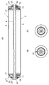
- FIG. (A) is sectional drawing which cut
- (B) and (C) are the left and right side views of a cylindrical lithium ion battery.
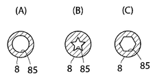
- It is an enlarged view of the principal part of FIG. (A)-(C) are figures which show the example of the cross-sectional shape of a hollow part. It is sectional drawing which shows the modification of an axial center.
- FIG. 1A is a cross-sectional view of a cylindrical lithium ion battery 1 according to an embodiment of the present invention cut along the longitudinal direction.
- FIGS. 1B and 1C are cylindrical lithium ion batteries.
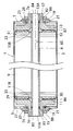
- FIG. FIG. 2 is an enlarged view of a main part of FIG. In FIG. 1 (A) and FIG. 2, illustration of the cross section of the electrode group 9 is abbreviate
- the cylindrical lithium ion battery 1 of the present embodiment includes a battery container body 3, a positive electrode side battery cover 5, a negative electrode side battery cover 7, a shaft core 8, an electrode group 9 infiltrated with an electrolyte, a positive electrode A current collector 11 and a negative electrode current collector 13 are provided.
- the battery container 2 is configured by the battery container body 3, the positive battery cover 5, and the negative battery cover 7.
- the battery container body 3 has a cylindrical shape with both ends opened by a nickel-plated steel material. Openings at both ends of the battery container body 3 are respectively closed by the positive battery cover 5 and the negative battery cover 7. As shown in FIG. 2, terminal through holes 5a and 7a are formed in the central portions of the positive electrode side battery cover 5 and the negative electrode side battery cover 7.
- An output terminal portion 15 of the positive electrode current collector 11 and an output terminal portion 17 of the negative electrode current collector 13 are inserted into the terminal through holes 5 a and 7 a through an insulating ring 19 and an insulating packing 21. Threaded portions are formed on the outer peripheral portions of the output terminal portions 15 and 17, and nut members 25 are screwed into the threaded portions. A washer 23 is disposed between the nut member 25 and the insulating ring 19.
- the positive electrode side battery cover 5 is provided with an electrolyte injection port 27 for containing an electrolyte.
- the electrolyte injection port 27 is sealed with a screw or the like (not shown).
- the electrode group 9 is configured by winding a belt-like positive electrode plate 29 and a belt-like negative electrode plate 31 around the shaft core 8 via a belt-like separator 33.
- the cross section cut in a direction perpendicular to the axis of the electrode group 9 is spiral.
- the positive electrode plate 29 of the present embodiment has a configuration in which a positive electrode mixture containing lithium manganate, which is a lithium transition metal double oxide, is applied almost uniformly on both surfaces of an aluminum foil as a positive electrode current collector plate.
- an uncoated portion 30 On one side in the longitudinal direction of the aluminum foil, an uncoated portion 30 that is not coated with the positive electrode mixture is formed.
- a plurality of tabs are integrally formed on the uncoated portion 30, and these tabs are welded to the positive electrode current collector 11.
- the negative electrode plate 31 has a configuration in which a negative electrode mixture containing carbon powder capable of occluding and releasing lithium ions as a negative electrode active material is applied almost uniformly on both surfaces of a rolled copper foil as a negative electrode current collector plate. On one side in the longitudinal direction of the copper foil, an uncoated portion 32 that is not coated with a negative electrode mixture is formed. A plurality of tabs are integrally formed on the uncoated portion 32, and these tabs are welded to the negative electrode current collector 13.
- the shaft core 8 is made of an insulating resin material and has a tubular shape.
- the shaft core 8 has a pair of extending portions 81 and 82 extending from the electrode group 9 at both ends.
- the pair of extending portions 81 and 82 pass through the inside of the battery container 2 and pass through the through holes 11A and 13A formed in the central portions of the positive electrode current collector 11 and the negative electrode current collector 13, respectively. Exposed outside.
- the shaft core 8 has a hollow portion 85 having openings 83 and 84 at both ends in the longitudinal direction.
- the pair of extending portions 81 and 82 located in the battery case 2 are respectively formed with annular groove portions 86 and 87 extending continuously in the circumferential direction of the shaft core 8.
- the grooves 86 and 87 constitute a valve.
- the grooves 86 and 87 constituting the valve are broken and opened when the internal pressure in the battery container 2 exceeds a predetermined pressure, and the internal space of the battery container 2 and the hollow part 85 of the shaft core 8 are in communication with each other. .
- the diameter of the through holes 11A and 13A formed in the central portions of the positive electrode current collector 11 and the negative electrode current collector 13 on the electrode group 9 side increases toward the electrode group 9, respectively.
- the taper portions 11B and 13B are formed. The taper portions 11B and 13B are opposed to the groove portions 86 and 87 constituting the valve in the radial direction. Therefore, the grooves 86 and 87 are not blocked.
- Two annular grooves are formed between the groove portions 86 and 87 and the openings 83 and 84 on the outer peripheral portions of the pair of extension portions 81 and 82, and in the two grooves, a seal is formed. O-rings 88 and 89 are fitted. O-rings 88 and 89 prevent the electrolyte from leaking to the outside.
- the openings are provided at both ends in the longitudinal direction with respect to the hollow portion 85 inside the shaft core 8, but the openings may be provided only at one end in the longitudinal direction of the shaft core 8. Good. In that case, the other end in the longitudinal direction of the shaft core 8 may be housed inside the battery container, and the negative electrode current collector is welded to the bottom wall of the battery container 2 so that the battery container serves as the negative electrode. That's fine.
- the shape of the grooves 86 and 87 constituting the valve is not limited to the present embodiment, and the cross-sectional shape may be V-shaped. In the present embodiment, it is needless to say that the valve may be configured by an independent recess instead of the annular groove.
- the hollow portion 85 is formed by a through-hole, but a reinforcing partition wall portion may be provided inside the hollow portion 85.
- a reinforcing partition wall portion may be provided inside the hollow portion 85.
- various shapes such as a circular shape, a star shape, and a polygonal shape can be adopted as the cross-sectional shape of the hollow portion 85.
- a plurality of recesses 85A and protrusions 85B for increasing the heat dissipation area may be formed on the wall surface surrounding the hollow portion 85.
- the present invention in addition to heat radiation from the battery case, if heat is actively radiated from the center of the electrode group, the temperature rise of the battery can be significantly suppressed.
- the valve since the valve is provided on the shaft core, the gas is released only through the opening of the shaft core, and the direction of gas discharge can be defined, thereby minimizing the influence of the gas on the surrounding parts. The advantage of being able to design for this is obtained.
Landscapes
- Chemical & Material Sciences (AREA)
- Chemical Kinetics & Catalysis (AREA)
- Electrochemistry (AREA)
- General Chemical & Material Sciences (AREA)
- Engineering & Computer Science (AREA)
- Manufacturing & Machinery (AREA)
- Secondary Cells (AREA)
- Materials Engineering (AREA)
- Gas Exhaust Devices For Batteries (AREA)
- Connection Of Batteries Or Terminals (AREA)
Abstract
La présente invention se rapporte à une batterie secondaire qui permet d'empêcher des augmentations de la température de la batterie et permet la régulation de la direction dans laquelle est évacué un gaz produit. La batterie secondaire comprend une paire d'extensions (81, 82) qui s'étendent depuis un groupe d'électrodes (9) sur un noyau axial (8). Le noyau axial (8) présente une partie creuse (85) pourvue d'une paire d'ouvertures (83, 84), une ouverture étant agencée sur l'extrémité de chaque paire d'extensions (81, 82) dans la direction longitudinale de cette dernière. Le groupe d'électrodes (9) est disposé dans un contenant de batterie (2) dans un état tel que les ouvertures (83, 84) au niveau des deux extrémités du noyau axial (8) communiquent chacune avec l'extérieur du contenant de batterie (2). Des rainures (86, 87), chaque rainure constituant des soupapes, sont agencées sur la paire d'extensions (81, 82) positionnées dans le contenant de batterie (2).
Priority Applications (1)
| Application Number | Priority Date | Filing Date | Title |
|---|---|---|---|
| JP2013501084A JP6127967B2 (ja) | 2011-02-24 | 2012-02-22 | 二次電池及びリチウムイオン電池 |
Applications Claiming Priority (2)
| Application Number | Priority Date | Filing Date | Title |
|---|---|---|---|
| JP2011-038554 | 2011-02-24 | ||
| JP2011038554 | 2011-02-24 |
Publications (1)
| Publication Number | Publication Date |
|---|---|
| WO2012115131A1 true WO2012115131A1 (fr) | 2012-08-30 |
Family
ID=46720907
Family Applications (1)
| Application Number | Title | Priority Date | Filing Date |
|---|---|---|---|
| PCT/JP2012/054216 Ceased WO2012115131A1 (fr) | 2011-02-24 | 2012-02-22 | Batterie secondaire et batterie au lithium-ion |
Country Status (2)
| Country | Link |
|---|---|
| JP (1) | JP6127967B2 (fr) |
| WO (1) | WO2012115131A1 (fr) |
Cited By (6)
| Publication number | Priority date | Publication date | Assignee | Title |
|---|---|---|---|---|
| FR3004292A1 (fr) * | 2013-04-09 | 2014-10-10 | Commissariat Energie Atomique | Accumulateur electrochimique au lithium avec boitier a dissipation thermique amelioree, pack-batterie et procedes de realisation associes. |
| EP3018732A4 (fr) * | 2014-07-31 | 2017-04-19 | Orange Power Ltd. | Batterie secondaire du type creuse et connecteur pour batterie secondaire du type creuse |
| EP3499603A1 (fr) * | 2017-12-14 | 2019-06-19 | Commissariat à l'Energie Atomique et aux Energies Alternatives | Traversee formant borne pour accumulateur electrochimique metal-ion, accumulateur associe |
| EP3499602A1 (fr) * | 2017-12-14 | 2019-06-19 | Commissariat à l'Energie Atomique et aux Energies Alternatives | Systeme de suivi des gaz au sein d'un pack-batterie, accumulateur electrochimique metal-ion associe comprenant une traversee formant borne pour integrant un event de securite pour le systeme de suivi |
| CN112510293A (zh) * | 2020-12-22 | 2021-03-16 | 成都市银隆新能源有限公司 | 电池及电池制造方法 |
| JP2023501017A (ja) * | 2020-09-28 | 2023-01-18 | 中山市小万能源科技有限公司 | 単電池及び電池パック |
Citations (4)
| Publication number | Priority date | Publication date | Assignee | Title |
|---|---|---|---|---|
| JPH09115551A (ja) * | 1995-10-23 | 1997-05-02 | Sony Corp | 円筒形二次電池の電極渦巻体の巻回方法及び巻回装置 |
| JP2002222666A (ja) * | 2001-01-25 | 2002-08-09 | Ngk Insulators Ltd | リチウム二次電池 |
| WO2011077775A1 (fr) * | 2009-12-25 | 2011-06-30 | トヨタ自動車株式会社 | Batterie |
| JP2011238569A (ja) * | 2010-05-13 | 2011-11-24 | Toyota Motor Corp | 電池、車両及び電池搭載機器 |
Family Cites Families (1)
| Publication number | Priority date | Publication date | Assignee | Title |
|---|---|---|---|---|
| JP2010111481A (ja) * | 2008-11-06 | 2010-05-20 | Panasonic Corp | キャリアテープ固定用のエンドテープ |
-
2012
- 2012-02-22 WO PCT/JP2012/054216 patent/WO2012115131A1/fr not_active Ceased
- 2012-02-22 JP JP2013501084A patent/JP6127967B2/ja active Active
Patent Citations (4)
| Publication number | Priority date | Publication date | Assignee | Title |
|---|---|---|---|---|
| JPH09115551A (ja) * | 1995-10-23 | 1997-05-02 | Sony Corp | 円筒形二次電池の電極渦巻体の巻回方法及び巻回装置 |
| JP2002222666A (ja) * | 2001-01-25 | 2002-08-09 | Ngk Insulators Ltd | リチウム二次電池 |
| WO2011077775A1 (fr) * | 2009-12-25 | 2011-06-30 | トヨタ自動車株式会社 | Batterie |
| JP2011238569A (ja) * | 2010-05-13 | 2011-11-24 | Toyota Motor Corp | 電池、車両及び電池搭載機器 |
Cited By (12)
| Publication number | Priority date | Publication date | Assignee | Title |
|---|---|---|---|---|
| FR3004292A1 (fr) * | 2013-04-09 | 2014-10-10 | Commissariat Energie Atomique | Accumulateur electrochimique au lithium avec boitier a dissipation thermique amelioree, pack-batterie et procedes de realisation associes. |
| WO2014167504A1 (fr) * | 2013-04-09 | 2014-10-16 | Commissariat A L'energie Atomique Et Aux Energies Alternatives | Accumulateur électrochimique au lithium avec boîtier a dissipation thermique améliorée, pack-batterie et procédés de réalisation associés |
| US9742045B2 (en) | 2013-04-09 | 2017-08-22 | Commissariat à l'Energie Atomique et aux Energies Alternatives | Lithium electrochemical storage battery having a casing providing improved thermal dissipation, associated battery pack and production processes |
| EP3018732A4 (fr) * | 2014-07-31 | 2017-04-19 | Orange Power Ltd. | Batterie secondaire du type creuse et connecteur pour batterie secondaire du type creuse |
| EP3499603A1 (fr) * | 2017-12-14 | 2019-06-19 | Commissariat à l'Energie Atomique et aux Energies Alternatives | Traversee formant borne pour accumulateur electrochimique metal-ion, accumulateur associe |
| EP3499602A1 (fr) * | 2017-12-14 | 2019-06-19 | Commissariat à l'Energie Atomique et aux Energies Alternatives | Systeme de suivi des gaz au sein d'un pack-batterie, accumulateur electrochimique metal-ion associe comprenant une traversee formant borne pour integrant un event de securite pour le systeme de suivi |
| FR3075477A1 (fr) * | 2017-12-14 | 2019-06-21 | Commissariat A L'energie Atomique Et Aux Energies Alternatives | Traversee formant borne pour accumulateur electrochimique metal-ion, accumulateur associe |
| FR3075475A1 (fr) * | 2017-12-14 | 2019-06-21 | Commissariat A L'energie Atomique Et Aux Energies Alternatives | Systeme de suivi des gaz au sein d'un pack-batterie, accumulateur electrochimique metal-ion associe comprenant une traversee formant borne pour integrant un event de securite pour le systeme de suivi |
| JP2019110122A (ja) * | 2017-12-14 | 2019-07-04 | コミッサリア ア レネルジー アトミーク エ オ ゼネルジ ザルタナテイヴ | 金属イオン電気化学蓄電池用の端子を形成するブッシング、および関連する蓄電池 |
| JP2023501017A (ja) * | 2020-09-28 | 2023-01-18 | 中山市小万能源科技有限公司 | 単電池及び電池パック |
| JP7374194B2 (ja) | 2020-09-28 | 2023-11-06 | 中山市小万能源科技有限公司 | 単電池及び電池パック |
| CN112510293A (zh) * | 2020-12-22 | 2021-03-16 | 成都市银隆新能源有限公司 | 电池及电池制造方法 |
Also Published As
| Publication number | Publication date |
|---|---|
| JP6127967B2 (ja) | 2017-05-17 |
| JPWO2012115131A1 (ja) | 2014-07-07 |
Similar Documents
| Publication | Publication Date | Title |
|---|---|---|
| JP6127967B2 (ja) | 二次電池及びリチウムイオン電池 | |
| US11916249B2 (en) | Cover assembly of secondary battery and secondary battery | |
| US11171384B2 (en) | Secondary battery | |
| EP2963703B1 (fr) | Batterie secondaire | |
| US10333120B2 (en) | Cylindrical secondary battery with reduced circumferential surface rupture | |
| US11749866B2 (en) | Secondary battery | |
| CN110021727B (zh) | 单向透气阀、二次电池的顶盖组件及二次电池 | |
| JP2011077020A (ja) | 二次電池及びその製造方法 | |
| WO2013122005A1 (fr) | Appareil de prévention des incendies à batterie | |
| JP2013161790A (ja) | 2次電池 | |
| KR100322100B1 (ko) | 밀폐전지 | |
| KR102201278B1 (ko) | 이차 전지 | |
| JP5279388B2 (ja) | 二次電池用センターピン、および二次電池 | |
| CN115398722B (zh) | 圆筒形电池 | |
| KR102161027B1 (ko) | 이차전지용 캡 조립체 | |
| KR101123407B1 (ko) | 극판과, 이를 구비하는 원통형 전지 | |
| WO2018097285A1 (fr) | Structure de borne et rondelle | |
| KR102245120B1 (ko) | 이차전지 및 그 이차전지의 제조 방법 | |
| JP2014041799A (ja) | 非水電解液二次電池 | |
| JP2015141821A (ja) | 非水電解液二次電池 | |
| JP2012204087A (ja) | 非水電解液二次電池及びリチウムイオン電池 | |
| KR20250042099A (ko) | 축전 셀 | |
| KR101777451B1 (ko) | 이차전지 전극조립체 | |
| JP2025033311A (ja) | 蓄電セル |
Legal Events
| Date | Code | Title | Description |
|---|---|---|---|
| 121 | Ep: the epo has been informed by wipo that ep was designated in this application |
Ref document number: 12749026 Country of ref document: EP Kind code of ref document: A1 |
|
| ENP | Entry into the national phase |
Ref document number: 2013501084 Country of ref document: JP Kind code of ref document: A |
|
| NENP | Non-entry into the national phase |
Ref country code: DE |
|
| 122 | Ep: pct application non-entry in european phase |
Ref document number: 12749026 Country of ref document: EP Kind code of ref document: A1 |