WO2012117461A1 - Dispositif et procédé de traitement de vidéo tridimensionnelle et dispositif d'affichage de vidéo tridimensionnelle - Google Patents
Dispositif et procédé de traitement de vidéo tridimensionnelle et dispositif d'affichage de vidéo tridimensionnelle Download PDFInfo
- Publication number
- WO2012117461A1 WO2012117461A1 PCT/JP2011/004932 JP2011004932W WO2012117461A1 WO 2012117461 A1 WO2012117461 A1 WO 2012117461A1 JP 2011004932 W JP2011004932 W JP 2011004932W WO 2012117461 A1 WO2012117461 A1 WO 2012117461A1
- Authority
- WO
- WIPO (PCT)
- Prior art keywords
- frame
- output
- video signal
- frames
- stereoscopic
- Prior art date
- Legal status (The legal status is an assumption and is not a legal conclusion. Google has not performed a legal analysis and makes no representation as to the accuracy of the status listed.)
- Ceased
Links
Images


Classifications
-
- H—ELECTRICITY
- H04—ELECTRIC COMMUNICATION TECHNIQUE
- H04N—PICTORIAL COMMUNICATION, e.g. TELEVISION
- H04N5/00—Details of television systems
- H04N5/14—Picture signal circuitry for video frequency region
- H04N5/144—Movement detection
-
- H—ELECTRICITY
- H04—ELECTRIC COMMUNICATION TECHNIQUE
- H04N—PICTORIAL COMMUNICATION, e.g. TELEVISION
- H04N13/00—Stereoscopic video systems; Multi-view video systems; Details thereof
- H04N13/10—Processing, recording or transmission of stereoscopic or multi-view image signals
- H04N13/106—Processing image signals
- H04N13/111—Transformation of image signals corresponding to virtual viewpoints, e.g. spatial image interpolation
-
- H—ELECTRICITY
- H04—ELECTRIC COMMUNICATION TECHNIQUE
- H04N—PICTORIAL COMMUNICATION, e.g. TELEVISION
- H04N19/00—Methods or arrangements for coding, decoding, compressing or decompressing digital video signals
- H04N19/50—Methods or arrangements for coding, decoding, compressing or decompressing digital video signals using predictive coding
- H04N19/587—Methods or arrangements for coding, decoding, compressing or decompressing digital video signals using predictive coding involving temporal sub-sampling or interpolation, e.g. decimation or subsequent interpolation of pictures in a video sequence
-
- H—ELECTRICITY
- H04—ELECTRIC COMMUNICATION TECHNIQUE
- H04N—PICTORIAL COMMUNICATION, e.g. TELEVISION
- H04N19/00—Methods or arrangements for coding, decoding, compressing or decompressing digital video signals
- H04N19/50—Methods or arrangements for coding, decoding, compressing or decompressing digital video signals using predictive coding
- H04N19/597—Methods or arrangements for coding, decoding, compressing or decompressing digital video signals using predictive coding specially adapted for multi-view video sequence encoding
-
- H—ELECTRICITY
- H04—ELECTRIC COMMUNICATION TECHNIQUE
- H04N—PICTORIAL COMMUNICATION, e.g. TELEVISION
- H04N7/00—Television systems
- H04N7/01—Conversion of standards, e.g. involving analogue television standards or digital television standards processed at pixel level
- H04N7/0127—Conversion of standards, e.g. involving analogue television standards or digital television standards processed at pixel level by changing the field or frame frequency of the incoming video signal, e.g. frame rate converter
- H04N7/0132—Conversion of standards, e.g. involving analogue television standards or digital television standards processed at pixel level by changing the field or frame frequency of the incoming video signal, e.g. frame rate converter the field or frame frequency of the incoming video signal being multiplied by a positive integer, e.g. for flicker reduction
-
- H—ELECTRICITY
- H04—ELECTRIC COMMUNICATION TECHNIQUE
- H04N—PICTORIAL COMMUNICATION, e.g. TELEVISION
- H04N13/00—Stereoscopic video systems; Multi-view video systems; Details thereof
- H04N2013/0074—Stereoscopic image analysis
- H04N2013/0085—Motion estimation from stereoscopic image signals
Definitions
- the present invention detects a motion vector between left and right images of a stereoscopic video signal and generates an interpolation frame using the detected motion vector, particularly a stereoscopic image captured at a frame frequency of 24 Hz.
- the present invention relates to a stereoscopic image processing apparatus that converts a movie material into a stereoscopic image of 60 Hz and performs frame sequential display at 120 Hz.
- the left and right images are displayed alternately on the display (frame sequential display), and the viewer enters the left or right eye in synchronization with the display.
- Wear LCD shutter glasses to block the image. Thereby, only the left image is recognized by the viewer's left eye and only the right image is recognized by the right eye, so that the viewer can perceive a stereoscopic effect by the parallax between the left and right images.
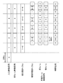
- FIG. 7 shows an example in which a scene where a ball crosses the screen is photographed at 24 Hz and displayed at 60 Hz by 3: 2 pull-down.
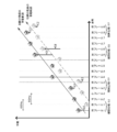
- FIG. 8 is a graph showing the relationship between the display position of the ball and the time in the video example of FIG.
- the line of sight follows the displayed ball and moves like the movement locus of the line of sight indicated by the arrow in the figure.
- the position of the ball coincides with the movement locus of the line of sight, but is shifted in other frames.
- the frames 1, 4 and 6 appear to be behind the position of the ball whose line of sight is chasing, and the frames 3, 5, and 8 appear to be on the front side, respectively.
- the moving ball appears to shake back and forth. Such a state is called film judder.
- FIG. 9 is a graph showing the relationship between the ball display position and time when a 24 Hz stereoscopic image is converted into a 60 Hz image by 3: 2 pull-down on each of the left and right sides and frame sequential display is performed at 120 Hz.
- FIG. 10 is a graph showing the deviation between the center of line of sight of the left and right eyes and the display position of the ball in this case, and the left and right parallax caused thereby. As can be seen from FIG.
- a motion vector is detected from a 24 Hz two-dimensional image, and an interpolation frame is generated and displayed in accordance with a display timing of 60 Hz using the motion vector, thereby displaying smooth motion without unnaturalness.
- Such frame frequency conversion is called a film dejadder.
- FIG. 11 is a graph showing the relationship between the ball display position and time when the scene of FIG.
- the film de-judger generates and displays an interpolated frame whose phase is shifted by +0.4 and +0.8 frames from the original frame of 24 Hz for frame 3 and frame 4, respectively.
- Interpolated frames whose phases are shifted by +0.2 and +0.6 frames from the frames are generated and displayed.
- the original frame of 24 Hz is displayed as it is.
- the display position of the moving ball coincides with the movement locus of the line of sight, and can be viewed as a smooth movement without film judder.
- the binocular parallax amount becomes constant and the viewer can easily obtain a stereoscopic effect.
- the motion vector used in frame frequency conversion is detected by comparing consecutive frames, so it can be detected correctly with respect to object movement, but it cannot detect motion such as rotation or enlargement / reduction correctly. There is.
- a correct motion vector cannot be detected for a region that is hidden in the background of a moving object, a region that appears from the background, or a region that is included in only one of the continuous frames.
- the normal motion vector is often detected by searching a predetermined range with reference to the detection target block, and a correct motion vector cannot be detected even when there is a motion exceeding the search range. Sometimes.
- an object of the present invention is to provide a stereoscopic video processing apparatus that performs frame frequency conversion suitable for stereoscopic video.
- a stereoscopic video processing apparatus for generating left and right output video signals having a frame frequency of 60 Hz from left and right input video signals having a frame frequency of 24 Hz is a block in a frame of the input video signal.
- a vector detection unit for detecting a motion vector of the input video signal, generating an interpolation frame based on the frame of the input video signal and the motion vector, and arranging the frame of the input video signal and the interpolation frame in a time axis direction to generate the output video signal
- An output image generation unit for generating the output image, and the output image generation so that the output video signal alternately outputs the interpolated frame every other frame and every other frame, and outputs the frame of the input video signal otherwise
- an output control unit for controlling the unit.
- the output image generation unit may generate the interpolated frame at a phase that divides the two frames of the input video signal into 1: 4. By generating the interpolation frame in a phase relatively close to the frame of the input video signal in this way, interpolation errors can be reduced.
- the stereoscopic video processing apparatus may include a frame frequency conversion unit including the vector detection unit, the output image generation unit, and the output control unit for each of the left and right signal systems of the stereoscopic video signal. Time sharing may be shared between the left and right signal systems of the video signal.
- Diagram explaining motion vector detection Diagram showing the timing relationship between input video and interpolation frame generation Diagram explaining generation of interpolation frame
- Diagram showing 3: 2 pull-down Diagram showing how the 3: 2 pull-down video looks A diagram showing how a 3: 2 pull-down 3D image looks The figure which shows the amount of parallax in 3: 2 pull-down stereoscopic video Figure showing how the film dejudged image looks
- FIG. 1 is a block diagram showing a main configuration of a stereoscopic video display apparatus 100 according to an embodiment of the present invention.
- the stereoscopic video display device 100 includes an input image selection unit 1, a stereoscopic video processing device 2, and a display unit 3.
- the stereoscopic video processing apparatus 2 includes two frame frequency conversion units 20 including a video memory 202, a vector detection unit 203, an output control unit 204, a vector memory 205, and an output image generation unit 206.
- the input image selection unit 1 divides the input stereoscopic video signal 101 into left and right input video signals 102 and outputs them to the stereoscopic video processing device 2.
- the stereoscopic video signal 101 is a stereoscopic video signal in which left and right images having a frame frequency of 24 Hz are alternately included.
- the stereoscopic video processing device 2 detects a motion vector between frames of the input left and right input video signals 102, generates an interpolation frame using the motion vectors, and generates left and right output video signals 103. To do. Specifically, the two frame frequency conversion units 20 process the left and right input video signals 102, respectively.
- the left and right video signals 103 output from the stereoscopic video processing device 2 are video signals having a frame frequency of 60 Hz.
- the display unit 3 alternately displays the left and right output video signals 103 output from the stereoscopic video processing device 2 at 120 Hz in a frame sequential manner.
- the display unit 3 is not particularly limited as long as it can display a stereoscopic video signal such as an LCD display or a PDP display.
- the stereoscopic video display device 100 performs stereoscopic display at 120 Hz by performing frame frequency conversion of the input stereoscopic video signal 101 of 24 Hz.
- the frame frequency conversion unit 20 performs frame frequency conversion (film dejudder) from the 24 Hz input video signal 102 to the 60 Hz output video signal 103.
- the input video signal 102 input to the frame frequency conversion unit 20 is input to the vector detection unit 203 and the video memory 202.
- the video memory 202 is a memory that can store an input video signal for at least three frames and can read any stored frame.
- the video memory 202 stores the input video signal and reads the input video signal of the previous frame and outputs it to the vector detection unit 203.
- the vector detection unit 203 divides the input video signal 102 into blocks of 8 pixels ⁇ 8 pixels, for example, and determines the position of the highest correlation from the previous frame video signal 104 input from the video memory 202 for each block.
- a motion vector is detected by searching. For example, as shown in FIG. 2, when detecting the motion vector of the target block in the frame (1), the position having the largest correlation with the target block is searched in the previous frame (0), and this position Is detected as a motion vector.
- the search range at this time is, for example, a range of horizontal ⁇ 64 pixels and vertical ⁇ 32 lines on the basis of a block for detecting a motion vector, and a position having the largest correlation is obtained in this range. Also, as the correlation value, the absolute value of the difference between the value of each pixel included in the block and the value of the pixel at the position to be compared is summed up for the entire block (SAD: Sum of AbsoluteifDifference, sum of absolute differences) ) Can be used.
- SAD Sum of AbsoluteifDifference, sum of absolute differences
- the block size is not limited to this, and it may be smaller or larger than this.
- the vector detection unit 203 outputs the detected motion vector 110 detected from the input video signal 102 and the previous frame video signal 104 to the vector memory 205.
- a vector memory 205 is a memory for storing a motion vector detected by the vector detection unit 203, and is for absorbing a time difference between writing from the vector detection unit 203 and reading from an output image generation unit 206 described later. .
- the vector memory 205 only needs to have a capacity corresponding to this time difference, but it is assumed here that a vector corresponding to two frames of the input video can be stored.
- the output control unit 204 reads out which one of the motion vectors corresponding to two frames stored in the vector memory 205, or before or after the interpolated frame generated from the video signals of a plurality of frames stored in the video memory 202. Which two frames are to be read out as frames and which phase between the two frames is to be generated is determined, and a control signal is output. Details of the output control unit 204 will be described later.
- the video memory 202 receives a frame selection signal 108 for determining two frames to be used for interpolation from the output control unit 204, and uses the two frames designated by the frame selection signal 108 as the previous and next frame video signals 105, as an output image generation unit 206. Output to.
- the vector memory 205 receives the vector selection signal 109 for selecting a vector to be used for interpolation from the output control unit 204, and outputs the motion vector designated by the vector selection signal 109 to the output image generation unit 206 as the interpolation motion vector 106. .
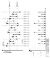
- the output control unit 204 outputs a frame selection signal 108, a vector selection signal 109, and an interpolation phase control signal 107 at a cycle of 5 frames as follows.
- the frame selection signal 108 for outputting the frame (0) is output as the previous frame, and 0 is output as the interpolation phase control signal 107. At this time, since no interpolation frame needs to be generated, an interpolation motion vector is unnecessary.
- the frame selection signal 108 for outputting the frame (0) and the frame (1) is output to the preceding and following frame video signal 105, and detected between the frame (1) and the frame (0) as the interpolation motion vector 106
- a signal for selecting a motion vector is output as the vector selection signal 109, and 0.2 is output as the interpolation phase control signal 107.
- the frame selection signal 108 for outputting the frame (1) is output as the previous frame, and 0 is output as the interpolation phase control signal 107. At this time, since no interpolation frame needs to be generated, the interpolation motion vector 106 is unnecessary.
- the frame selection signal 108 for outputting the frame (1) is output as the previous frame, and 0 is output as the interpolation phase control signal 107. At this time, since no interpolation frame needs to be generated, the interpolation motion vector 106 is unnecessary.
- the frame selection signal 108 for outputting the frame (1) and the frame (2) is output to the preceding and following frame video signal 105, and detected as the interpolation motion vector 106 between the frame (2) and the frame (1).
- a signal for selecting a motion vector is output as the vector selection signal 109 and 0.8 is output as the interpolation phase control signal 107.
- the output video signal 103 Is frame (0), frame (0.2), frame (1), frame (1), frame (1.8), frame (2), frame (2.2), frame (3), frame (3 ), Frame (3.8), and frame (4).
- the output control unit 204 appropriately selects an input frame and a motion vector necessary for generating an interpolation frame as described above, and outputs a control signal for inputting them to the output image generation unit 206. In accordance with this, the output control unit 204 outputs the interpolation phase control signal 107.
- the output image generation unit 206 uses the two frames input as the preceding and following frame video signal 105 and the interpolation motion vector 106 corresponding to the motion between the two frames, and uses the interpolation phase control signal 107 to specify the interpolation phase. And an output video signal 103 is output.
- the generation of the interpolation frame can be performed by moving at least one pixel or pixel block of the frame before and after the generated interpolation frame along the interpolation motion vector 106.
- the position on the time axis for generating the interpolation frame that is, the interpolation phase
- the interpolation phase can be arbitrarily selected between the frame (F-1) and the frame (F).
- a fixed percentage of pixels moved from both frames, or the interpolation phase It is also possible to generate by mixing at a ratio corresponding to FIG. 4 shows an example in which an interpolation frame is generated with an interpolation phase of 1/5 from the frame (F-1).
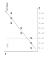
- FIG. 5 is a graph showing the relationship between the display position of the ball and the time when a stereoscopic image obtained by stereoscopically shooting the scene of FIG. 7 at 24 Hz is displayed on the stereoscopic image display device 100.
- FIG. 6 is a graph showing the deviation between the center of line of sight of the left and right eyes and the display position of the ball in this case, and the left and right parallax caused thereby.
- the binocular parallax amount of the output image is N ⁇ 1 / 5V between many frames.
- N + 2 / 5V it can be seen that the variation in the amount of parallax is suppressed in the stereoscopic video displayed on the stereoscopic video display device 100 according to the present embodiment. As a result, high-quality stereoscopic display is possible.
- the frame frequency conversion method disclosed in this specification uses a small interpolation frame ratio and uses only the interpolation phase close to the input frame, so that image quality degradation is small when an incorrect motion vector is detected.
- an interpolation frame is generated and output for a part of the frames having a large influence on the parallax.
- the parallax between the left and right images of the input image is detected, and the parallax and the motion vector are detected.
- the amount of parallax between the left and right images when 3: 2 pull-down display is performed based on the size may be calculated, and when the amount of parallax is outside a predetermined range, an interpolation frame may be generated.
- the generation of the interpolated image is determined for each frame.
- the generation of the interpolated image may be determined for each image area in the frame.
- the size of the image area may be the same as the block in motion vector detection, or may be a different size. For example, when an object crosses a screen without motion, an interpolation image is generated only for an image region including the moving object. As a result, high-quality stereoscopic display is possible by generating an interpolated image for an image area that includes a moving object.
- the ratio of the interpolated image in the output image is small, image quality deterioration due to an interpolation error is suppressed. it can.
- the description is based on the assumption that a 24 Hz stereoscopic video signal 101 is input.
- the stereoscopic video signal 101 is a 60 Hz stereoscopic video signal that is 3: 2 pulled down. It doesn't matter. If a 24 Hz stereoscopic video signal before being 3: 2 pulled down can be appropriately selected from a 3: 2 pulled down 60 Hz stereoscopic video signal, the same processing can be performed.
- each signal shown in FIG. 3 is an example, and depending on the capacity of the video memory 202 and the vector memory 205, it is possible to perform processing at a different timing.
- the interpolation phase of the generated interpolation frame is not limited to 0.2 and 0.8. These neighborhood values, for example, 0.19 and 0.81 may be used.
- the interpolation phase of the interpolation frame may gradually approach 0.2 or 0.8.
- the interpolation phase may be gradually brought closer to 0 instead of suddenly becoming 0.
- the output control unit 204 gradually changes the value of the interpolation phase control signal 107.
- the video memory 202 and the vector memory 205 do not need to be provided in the stereoscopic video processing device 2, and an external memory may be used.
- the stereoscopic video processing device 2 includes the two frame frequency conversion units 20.
- one frame frequency conversion unit 20 is time-divided in the left and right signal systems of the stereoscopic video signal. You may make it share.
- the present invention can be used for an apparatus that detects a motion vector from a stereoscopic video signal, converts the frame frequency using the detected motion vector, and displays the same.
Landscapes
- Engineering & Computer Science (AREA)
- Multimedia (AREA)
- Signal Processing (AREA)
- Testing, Inspecting, Measuring Of Stereoscopic Televisions And Televisions (AREA)
- Television Systems (AREA)
Abstract
L'invention porte sur un dispositif de traitement de vidéo tridimensionnelle qui, à partir d'un signal vidéo d'entrée gauche et droit ayant une fréquence de trame de 24 Hz, génère respectivement un signal vidéo de sortie gauche et droit ayant une fréquence de trame de 60 Hz, lequel dispositif de traitement de vidéo tridimensionnelle comprend : une unité de détection de vecteur (203) qui détecte des vecteurs de mouvement de blocs dans les trames du signal vidéo d'entrée ; une unité de génération d'image de sortie (206) qui génère des trames interpolées sur la base des vecteurs de mouvement et des trames du signal vidéo d'entrée, et génère un signal vidéo de sortie par agencement des trames du signal vidéo d'entrée et des trames interpolées dans la direction de l'axe temporel ; et une unité de commande de sortie (204) qui commande l'unité de génération d'image de sortie d'une manière telle que des trames interpolées sont émises de manière alternée après chaque trame et après toutes les deux trames en tant que signal vidéo de sortie, en dehors desquelles les trames du signal vidéo d'entrée sont émises.
Priority Applications (2)
| Application Number | Priority Date | Filing Date | Title |
|---|---|---|---|
| JP2012526782A JP5325341B2 (ja) | 2011-03-03 | 2011-09-02 | 立体映像処理装置および方法ならびに立体映像表示装置 |
| US13/543,406 US9210301B2 (en) | 2011-03-03 | 2012-07-06 | Generation interpolation frames |
Applications Claiming Priority (2)
| Application Number | Priority Date | Filing Date | Title |
|---|---|---|---|
| JP2011-046677 | 2011-03-03 | ||
| JP2011046677 | 2011-03-03 |
Related Child Applications (1)
| Application Number | Title | Priority Date | Filing Date |
|---|---|---|---|
| US13/543,406 Continuation US9210301B2 (en) | 2011-03-03 | 2012-07-06 | Generation interpolation frames |
Publications (1)
| Publication Number | Publication Date |
|---|---|
| WO2012117461A1 true WO2012117461A1 (fr) | 2012-09-07 |
Family
ID=46757431
Family Applications (1)
| Application Number | Title | Priority Date | Filing Date |
|---|---|---|---|
| PCT/JP2011/004932 Ceased WO2012117461A1 (fr) | 2011-03-03 | 2011-09-02 | Dispositif et procédé de traitement de vidéo tridimensionnelle et dispositif d'affichage de vidéo tridimensionnelle |
Country Status (3)
| Country | Link |
|---|---|
| US (1) | US9210301B2 (fr) |
| JP (1) | JP5325341B2 (fr) |
| WO (1) | WO2012117461A1 (fr) |
Cited By (1)
| Publication number | Priority date | Publication date | Assignee | Title |
|---|---|---|---|---|
| WO2020039956A1 (fr) * | 2018-08-22 | 2020-02-27 | ソニー株式会社 | Dispositif d'affichage, dispositif de traitement de signaux et procédé de traitement de signaux |
Families Citing this family (4)
| Publication number | Priority date | Publication date | Assignee | Title |
|---|---|---|---|---|
| WO2012117461A1 (fr) * | 2011-03-03 | 2012-09-07 | パナソニック株式会社 | Dispositif et procédé de traitement de vidéo tridimensionnelle et dispositif d'affichage de vidéo tridimensionnelle |
| US9805472B2 (en) * | 2015-02-18 | 2017-10-31 | Sony Corporation | System and method for smoke detection during anatomical surgery |
| US10398976B2 (en) | 2016-05-27 | 2019-09-03 | Samsung Electronics Co., Ltd. | Display controller, electronic device, and virtual reality device |
| US20190108400A1 (en) * | 2017-10-05 | 2019-04-11 | Qualcomm Incorporated | Actor-deformation-invariant action proposals |
Citations (4)
| Publication number | Priority date | Publication date | Assignee | Title |
|---|---|---|---|---|
| JP2005260810A (ja) * | 2004-03-15 | 2005-09-22 | Matsushita Electric Ind Co Ltd | カメラレコーダ |
| JP2010226243A (ja) * | 2009-03-19 | 2010-10-07 | Sony Corp | 映像信号処理装置、立体映像表示装置、立体映像伝送表示システムおよび映像信号処理方法 |
| JP2010268037A (ja) * | 2009-05-12 | 2010-11-25 | Panasonic Corp | 映像変換方法および映像変換装置 |
| WO2011099267A1 (fr) * | 2010-02-15 | 2011-08-18 | パナソニック株式会社 | Dispositif de traitement vidéo et procédé de traitement vidéo |
Family Cites Families (10)
| Publication number | Priority date | Publication date | Assignee | Title |
|---|---|---|---|---|
| JP3108287B2 (ja) | 1994-09-22 | 2000-11-13 | 三洋電機株式会社 | 2次元映像を3次元映像に変換する方法 |
| DE69528946T2 (de) | 1994-09-22 | 2003-10-02 | Sanyo Electric Co., Ltd. | Verfahren zum Umsetzen von zweidimensionalen Bildern in dreidimensionale Bilder |
| JP2846836B2 (ja) | 1994-09-22 | 1999-01-13 | 三洋電機株式会社 | 2次元映像を3次元映像に変換する方法 |
| JP3495485B2 (ja) * | 1995-12-19 | 2004-02-09 | 日本放送協会 | 画像変換装置 |
| JP2008187222A (ja) * | 2007-01-26 | 2008-08-14 | Hitachi Ltd | 動きベクトル検出装置、動きベクトル検出方法、映像表示装置 |
| JP4513819B2 (ja) * | 2007-03-19 | 2010-07-28 | 株式会社日立製作所 | 映像変換装置、映像表示装置、映像変換方法 |
| JP4626779B2 (ja) * | 2008-08-26 | 2011-02-09 | ソニー株式会社 | 映像信号処理装置、画像表示装置および映像信号処理方法 |
| JP4620163B2 (ja) * | 2009-06-30 | 2011-01-26 | 株式会社東芝 | 静止字幕検出装置、静止字幕を含む画像を表示する映像機器、および静止字幕を含んだ画像の処理方法 |
| JP5532232B2 (ja) * | 2010-05-18 | 2014-06-25 | ソニー株式会社 | 映像信号処理装置、映像表示装置および映像表示システム |
| WO2012117461A1 (fr) * | 2011-03-03 | 2012-09-07 | パナソニック株式会社 | Dispositif et procédé de traitement de vidéo tridimensionnelle et dispositif d'affichage de vidéo tridimensionnelle |
-
2011
- 2011-09-02 WO PCT/JP2011/004932 patent/WO2012117461A1/fr not_active Ceased
- 2011-09-02 JP JP2012526782A patent/JP5325341B2/ja not_active Expired - Fee Related
-
2012
- 2012-07-06 US US13/543,406 patent/US9210301B2/en not_active Expired - Fee Related
Patent Citations (4)
| Publication number | Priority date | Publication date | Assignee | Title |
|---|---|---|---|---|
| JP2005260810A (ja) * | 2004-03-15 | 2005-09-22 | Matsushita Electric Ind Co Ltd | カメラレコーダ |
| JP2010226243A (ja) * | 2009-03-19 | 2010-10-07 | Sony Corp | 映像信号処理装置、立体映像表示装置、立体映像伝送表示システムおよび映像信号処理方法 |
| JP2010268037A (ja) * | 2009-05-12 | 2010-11-25 | Panasonic Corp | 映像変換方法および映像変換装置 |
| WO2011099267A1 (fr) * | 2010-02-15 | 2011-08-18 | パナソニック株式会社 | Dispositif de traitement vidéo et procédé de traitement vidéo |
Cited By (4)
| Publication number | Priority date | Publication date | Assignee | Title |
|---|---|---|---|---|
| WO2020039956A1 (fr) * | 2018-08-22 | 2020-02-27 | ソニー株式会社 | Dispositif d'affichage, dispositif de traitement de signaux et procédé de traitement de signaux |
| JPWO2020039956A1 (ja) * | 2018-08-22 | 2021-08-10 | ソニーグループ株式会社 | 表示装置、信号処理装置、及び信号処理方法 |
| US11930207B2 (en) | 2018-08-22 | 2024-03-12 | Saturn Licensing Llc | Display device, signal processing device, and signal processing method |
| JP7630993B2 (ja) | 2018-08-22 | 2025-02-18 | サターン ライセンシング エルエルシー | 表示装置、信号処理装置、及び信号処理方法 |
Also Published As
| Publication number | Publication date |
|---|---|
| JPWO2012117461A1 (ja) | 2014-07-07 |
| US9210301B2 (en) | 2015-12-08 |
| JP5325341B2 (ja) | 2013-10-23 |
| US20120281076A1 (en) | 2012-11-08 |
Similar Documents
| Publication | Publication Date | Title |
|---|---|---|
| US9237334B2 (en) | Method and device for controlling subtitle applied to display apparatus | |
| TWI428007B (zh) | 視訊處理裝置及方法 | |
| JP4748251B2 (ja) | 映像変換方法および映像変換装置 | |
| US20120033038A1 (en) | Apparatus and method for generating extrapolated view | |
| JP5325341B2 (ja) | 立体映像処理装置および方法ならびに立体映像表示装置 | |
| CA2783588C (fr) | Procede et appareil pour une reproduction optimale de mouvement dans un cinema numerique stereoscopique | |
| US20120307153A1 (en) | Video processing device and video processing method | |
| US9113140B2 (en) | Stereoscopic image processing device and method for generating interpolated frame with parallax and motion vector | |
| JP5478728B2 (ja) | 立体映像処理装置および方法ならびに立体映像表示装置 | |
| WO2012117464A1 (fr) | Dispositif et procédé de traitement de vidéo tridimensionnelle et dispositif d'affichage de vidéo tridimensionnelle | |
| WO2012117462A1 (fr) | Dispositif et procédé de traitement de vidéo tridimensionnelle et dispositif d'affichage de vidéo tridimensionnelle | |
| US9330487B2 (en) | Apparatus and method for processing 3D images through adjustment of depth and viewing angle | |
| JP2012182691A (ja) | 画像変換装置 | |
| JP2014207492A (ja) | 立体映像表示装置 | |
| JP5700998B2 (ja) | 立体映像表示装置及びその制御方法 | |
| JP5490252B2 (ja) | 立体画像処理装置、立体画像表示装置及び立体画像処理方法 | |
| US8953018B2 (en) | Generation and display of stereoscopic images | |
| US8902286B2 (en) | Method and apparatus for detecting motion vector, and method and apparatus for processing image signal | |
| JP2012015825A (ja) | 映像変換方法および映像変換装置 | |
| JP2012175309A (ja) | 映像表示装置および映像表示方法 | |
| JP2012100186A (ja) | 補間画像生成装置 |
Legal Events
| Date | Code | Title | Description |
|---|---|---|---|
| WWE | Wipo information: entry into national phase |
Ref document number: 2012526782 Country of ref document: JP |
|
| 121 | Ep: the epo has been informed by wipo that ep was designated in this application |
Ref document number: 11859927 Country of ref document: EP Kind code of ref document: A1 |
|
| NENP | Non-entry into the national phase |
Ref country code: DE |
|
| 122 | Ep: pct application non-entry in european phase |
Ref document number: 11859927 Country of ref document: EP Kind code of ref document: A1 |