WO2012117543A1 - Accumulateur électrique - Google Patents
Accumulateur électrique Download PDFInfo
- Publication number
- WO2012117543A1 WO2012117543A1 PCT/JP2011/054798 JP2011054798W WO2012117543A1 WO 2012117543 A1 WO2012117543 A1 WO 2012117543A1 JP 2011054798 W JP2011054798 W JP 2011054798W WO 2012117543 A1 WO2012117543 A1 WO 2012117543A1
- Authority
- WO
- WIPO (PCT)
- Prior art keywords
- charge
- positive electrode
- electrode electrolyte
- negative electrode
- aqueous solution
- Prior art date
- Legal status (The legal status is an assumption and is not a legal conclusion. Google has not performed a legal analysis and makes no representation as to the accuracy of the status listed.)
- Ceased
Links
Images

Classifications
-
- H—ELECTRICITY
- H01—ELECTRIC ELEMENTS
- H01M—PROCESSES OR MEANS, e.g. BATTERIES, FOR THE DIRECT CONVERSION OF CHEMICAL ENERGY INTO ELECTRICAL ENERGY
- H01M8/00—Fuel cells; Manufacture thereof
- H01M8/18—Regenerative fuel cells, e.g. redox flow batteries or secondary fuel cells
- H01M8/184—Regeneration by electrochemical means
- H01M8/188—Regeneration by electrochemical means by recharging of redox couples containing fluids; Redox flow type batteries
-
- Y—GENERAL TAGGING OF NEW TECHNOLOGICAL DEVELOPMENTS; GENERAL TAGGING OF CROSS-SECTIONAL TECHNOLOGIES SPANNING OVER SEVERAL SECTIONS OF THE IPC; TECHNICAL SUBJECTS COVERED BY FORMER USPC CROSS-REFERENCE ART COLLECTIONS [XRACs] AND DIGESTS
- Y02—TECHNOLOGIES OR APPLICATIONS FOR MITIGATION OR ADAPTATION AGAINST CLIMATE CHANGE
- Y02E—REDUCTION OF GREENHOUSE GAS [GHG] EMISSIONS, RELATED TO ENERGY GENERATION, TRANSMISSION OR DISTRIBUTION
- Y02E60/00—Enabling technologies; Technologies with a potential or indirect contribution to GHG emissions mitigation
- Y02E60/30—Hydrogen technology
- Y02E60/50—Fuel cells
Definitions
- the present invention relates to a power storage battery such as a redox flow battery.
- Patent Document 1 and Non-Patent Document 1 describe a configuration (electromotive force) in which hydrochloric acid (solvent is water) is used as the electrolyte, the positive electrode electrolyte is an aqueous hydrochloric acid solution of iron chloride, and the negative electrode electrolyte is an aqueous hydrochloric acid solution of chromium chloride. Is about 1.0V).
- Patent Documents 2 and 3 and Non-Patent Document 2 sulfuric acid (solvent is water) is used as the electrolyte, and the positive and negative electrolytes are vanadium sulfate aqueous solutions (electromotive force is about 1.4 V). )
- the electrolyte in each of these structures is strongly acidic, and there are difficulties in handling and selection of the battery container material. Therefore, a redox flow battery using a weakly acidic, neutral, or weakly alkaline (pH 3 to 8) electrolyte is required.
- Non-Patent Documents 3 to 5 propose a configuration in which the negative electrode electrolyte is an aqueous solution of a Cr-EDTA (ethylenediaminetetraacetic acid) complex.
- the above Cr-EDTA complex can satisfactorily perform a redox reaction under conditions of pH 3-8.
- the positive electrode electrolyte in each of these structures is strongly acidic, and therefore there are still difficulties in handling and selection of battery container materials.
- Non-Patent Document 6 sodium acetate (solvent is water) is used as the electrolyte, the negative electrode electrolyte is a sodium acetate aqueous solution of Cr—EDTA complex, and the positive electrode electrolyte is a sodium acetate aqueous solution of Cr—EDTA complex. And a configuration in which the positive electrode electrolyte is a sodium acetate aqueous solution of Fe-EDTA complex (electromotive force is about 1.2 V) are proposed.
- Non-Patent Document 6 allows the redox reaction of the negative electrode side active material Cr-EDTA complex to be carried out satisfactorily on the negative electrode side under the conditions of pH 3-8.
- Cr compound ions cannot be dissolved in water and self-discharged, so that the charge / discharge cycle characteristics (reversibility) are inferior, and the Coulomb efficiency (50% or less) and It is inferior in energy efficiency and is not suitable as a power storage battery to be used repeatedly.
- the positive electrode electrolyte is an aqueous sodium acetate solution of Fe-EDTA complex, the ions of the Fe compound cannot be dissolved in water and precipitate on the positive electrode side under the conditions of pH 3-8.
- transition metals generally used in redox flow type batteries are used.
- the oxide or hydroxide becomes insoluble in water and precipitates under conditions of pH 3-8.
- the region in which transition metal ions can be dissolved in water is extremely narrow (the ions can be dissolved in water under strongly acidic conditions, but the ions are water under conditions of pH 3-8. Can not be dissolved in).
- the present inventor has intensively studied to find a suitable active material on the positive electrode side. That is, the inventors have eagerly searched for a compound containing a metal that can change its valence in an ionic state without causing the oxide or hydroxide to be insoluble in water under the conditions of pH 3-8.
- Mn is determined from the potential-pH diagram that oxides (MnO 2 and Mn 2 O 3 ) generated by charging and discharging are insoluble in water and precipitate, By doing so, it was found that the valence can be changed in an ionic state without the oxide or hydroxide being insoluble in water under the conditions of pH 3-8.
- the present invention was completed.
- the present invention has been made in view of the above problems, and its main purpose is that the pH of the positive electrode electrolyte and the negative electrode electrolyte is in the range of 3 to 8, which is excellent in handleability and charge / discharge.
- An object of the present invention is to provide a power storage battery excellent in various performances such as cycle characteristics (reversibility), energy efficiency, and Coulomb efficiency.
- the power storage battery according to the present invention has an aminopolycarboxylic acid chelate wherein the pH of the positive electrode electrolyte and the negative electrode electrolyte is in the range of 3 to 8, and the positive electrode electrolyte is Mn. It is characterized by being an aqueous solution containing.
- the aminopolycarboxylic acid chelate of Mn used as the active material on the positive electrode side does not generate oxides or hydroxides within a pH range of 3 to 8, and therefore has good charge / discharge cycle characteristics (reversibility).
- it is excellent in energy efficiency and coulomb efficiency, and can withstand the use of several thousand cycles, so it has excellent performance as a power storage battery that is used repeatedly.
- the positive electrode electrolyte and the negative electrode electrolyte are not strongly acidic, they are excellent in handleability and increase the degree of freedom in selecting the battery container material.
- the positive electrode electrolyte and the negative electrode electrolyte are strongly acidic, there are restrictions on the selection of materials that can be used as battery containers (for example, hydrolyzed plastic cannot be used), Since the positive electrode electrolyte and the negative electrode electrolyte are not strongly acidic, general-purpose plastics and relatively inexpensive metals such as Sn, Al, Ti, Cu, Fe, and Ni can be used. Therefore, according to said structure, while being excellent in handleability, the power storage battery excellent in various performances, such as charging / discharging cycling characteristics (reversibility), energy efficiency, and Coulomb efficiency, can be provided comparatively cheaply. .
- the positive electrode electrolyte is more preferably an aqueous solution containing a Mn-EDTA complex, and the concentration of the Mn-EDTA complex in the aqueous solution is 0.2 mol / L or more, 1.0 More preferably, it is at most mol / L.
- the negative electrode electrolyte is more preferably an aqueous solution containing a Cr—EDTA complex.
- the positive electrode electrolyte and the negative electrode electrolyte are more preferably an aqueous solution containing a Mn-EDTA complex and a Cr-EDTA complex.
- the power storage battery according to the present invention is more preferably a redox flow battery.
- the concentration of the Mn-EDTA complex in the aqueous solution is set to a relatively high concentration (1.0 mol / L or less). Therefore, the energy density of the power storage battery can be increased.
- the positive electrode electrolyte and the negative electrode electrolyte are aqueous solutions containing a Mn-EDTA complex and a Cr-EDTA complex (so-called premix method)
- the capacity of the power storage battery (Various performances) can be kept constant for a longer period of time, so that the maintenance of the power storage battery becomes easier.
- the power storage battery of the present invention it is possible to provide a power storage battery that is excellent in handleability and excellent in various performances such as charge / discharge cycle characteristics (reversibility), energy efficiency, and coulomb efficiency at a relatively low cost. There is an effect that can be.
- the power storage battery according to the present invention is easy to mass-produce (industrialize) at a relatively low cost as compared with the conventional power storage battery.
- the power storage battery according to the present invention has a configuration in which the pH of the positive electrode electrolyte and the negative electrode electrolyte is in the range of 3 to 8, and the positive electrode electrolyte is an aqueous solution containing an aminopolycarboxylic acid chelate of Mn.
- Mn aminopolycarboxylic acid chelate refers to a Mn complex (organometallic complex) using aminopolycarboxylic acid as a chelating agent.
- pH 3 to 8 means that the pH is 3 or more and 8 or less.
- EDTA refers to ethylenediaminetetraacetic acid.
- a redox flow battery is taken as an example of the power storage battery.
- the present invention is not limited to this, and can be implemented in a mode in which various modifications are added within the range described.
- the redox flow battery 1 mainly includes a charge / discharge cell (battery container) 2, a positive electrode electrolyte tank 3, and a negative electrode electrolyte tank 4.
- the inside of the charge / discharge cell 2 is partitioned into a positive electrode side cell 2a and a negative electrode side cell 2b by a diaphragm 11 made of, for example, an ion exchange membrane.
- the charge / discharge cell 2 may be provided with a temperature control device that keeps the temperature constant.
- the positive electrode side cell 2a accommodates a current collector plate 12 such as a glassy carbon plate and a positive electrode 13 made of, for example, carbon felt.
- the negative electrode side cell 2b accommodates a current collector plate 14 such as a glassy carbon plate and a negative electrode 15 made of, for example, carbon felt.
- the positive electrode 13 is impregnated with a positive electrode electrolyte
- the negative electrode 15 is impregnated with a negative electrode electrolyte. Since the positive electrode electrolyte and the negative electrode electrolyte are not strongly acidic and poor in corrosivity, they are excellent in handleability.
- the current collecting plates 12 and 14 are electrically connected to the charging / discharging device 10.
- the positive electrode 13 performs a reduction reaction and receives electrons
- the negative electrode 15 performs an oxidation reaction and emits electrons.
- the current collecting plate 12 receives electrons from the charging / discharging device 10 and supplies them to the positive electrode 13, and the current collecting plate 14 collects electrons emitted from the negative electrode 15 and collects them in the charging / discharging device 10. It comes to supply.
- the positive electrode 13 performs an oxidation reaction and emits electrons
- the negative electrode 15 performs a reduction reaction and receives electrons.
- the current collector 12 collects the electrons emitted from the positive electrode 13 and supplies them to the charging / discharging device 10.
- the current collector 14 receives the electrons from the charging / discharging device 10 and supplies them to the negative electrode 15. It comes to supply.
- the positive electrode electrolyte tank 3 is a tank for storing the positive electrode electrolyte, and is connected to the positive electrode side cell 2a. That is, the positive electrode electrolyte tank 3 supplies the positive electrode electrolyte to the positive electrode 13 in the positive electrode side cell 2a through the supply pipe 3a, and the positive electrode electrolyte that has passed through the positive electrode 13 passes through the recovery pipe 3b. It comes to collect.
- the positive electrode electrolyte is circulated by a pump 5 provided in the supply pipe 3a.
- the supply amount of the positive electrode electrolyte per unit time to the positive electrode side cell 2a at the time of charge / discharge and the capacity of the positive electrode electrolyte tank 3 depend on the size of the charge / discharge cell 2, the capacity required for the redox flow battery 1 and the like. There is no particular limitation.
- the negative electrode electrolyte tank 4 is a tank for storing the negative electrode electrolyte, and is connected to the negative electrode side cell 2b. That is, the negative electrode electrolyte tank 4 supplies the negative electrode electrolyte to the negative electrode 15 in the negative electrode side cell 2b through the supply pipe 4a, and the negative electrode electrolyte that has passed through the negative electrode 15 passes through the recovery pipe 4b. It comes to collect.
- the negative electrode electrolyte is circulated by a pump 6 provided in the supply pipe 4a.
- the supply amount of the negative electrode electrolyte per unit time to the negative electrode side cell 2b during charge / discharge and the capacity of the negative electrode electrolyte tank 4 depend on the size of the charge / discharge cell 2 and the capacity required of the redox flow battery 1 and the like. There is no particular limitation.
- the electrolyte in the charge / discharge cell 2 can be exchanged. Therefore, in the redox flow battery 1 according to the present embodiment, a long-time (so-called large-capacity battery). ) Charging and discharging are possible.
- the charge / discharge cell 2, the positive electrode electrolyte tank 3 and the negative electrode electrolyte tank 4 are supplied with an inert gas such as nitrogen gas from a gas supply device (not shown) through an inert gas supply pipe 7. Thereby, the positive electrode electrolyte and the negative electrode electrolyte are shielded from oxygen in the atmosphere.
- the inert gas supplied from the inert gas supply pipe 7 is exhausted to the outside through the exhaust pipe 8.
- the front end of the exhaust pipe 8 is sealed with a water-sealed pipe 9 to prevent backflow of the atmosphere and keep the air pressure in the charge / discharge cell 2, the positive electrode electrolyte tank 3 and the negative electrode electrolyte tank 4 constant. ing.
- the inert gas supply pipe 7 may supply an inert gas to the gas phase portion of the charge / discharge cell 2 and the positive electrode electrolyte tank 3 and the negative electrode electrolyte tank 4. And you may come to supply by bubbling in a negative electrode electrolyte solution.
- the material of each constituent member constituting the redox flow battery 1 Great freedom of choice. That is, if the positive electrode electrolyte and the negative electrode electrolyte are strongly acidic, there are restrictions on the selection of materials that can be used as battery containers (for example, plastics that are hydrolyzed cannot be used), Since the positive electrode electrolyte and the negative electrode electrolyte are not strongly acidic, specific examples of the material of the charge / discharge cell 2 include, for example, general-purpose plastics and relatively, such as Sn, Al, Ti, Cu, Fe, and Ni. An inexpensive metal can be used.
- the materials exemplified above can also be used as materials for the positive electrode electrolyte tank 3, the pump 5, the supply pipe 3a, the recovery pipe 3b, the negative electrode electrolyte tank 4, the pump 6, the supply pipe 4a, and the recovery pipe 4b. Therefore, the redox flow battery 1 can be manufactured at a relatively low cost. Further, since it is poorly corrosive, the service life of the redox flow battery 1 is longer than that of a conventional redox flow battery (using a strongly acidic electrolyte). Therefore, the redox flow battery 1 is easy to mass-produce (industrialize) at a relatively low cost as compared with the conventional redox flow battery (using a strongly acidic electrolyte).
- each constituent member constituting the redox flow type battery 1 has an appropriate mechanical strength sufficient to maintain the apparatus, and may be made of a material that is not corroded by the positive electrode electrolyte and the negative electrode electrolyte.
- the material is not limited to the above exemplified materials.
- the negative electrode electrolyte has a pH in the range of 3 to 8, more preferably in the range of 4 to 7, and can perform a good redox reaction under the conditions of pH 3 to 8 (charged in the ionic state).
- the aqueous solution may contain an active material on the negative electrode side (which changes in number).
- Specific examples of the negative electrode electrolyte include an aqueous solution containing a Cr-EDTA complex, an aqueous solution containing a Ti-EDTA complex, an aqueous solution containing a V-EDTA complex, and an aqueous solution containing an Fe-EDTA complex. Of these, an aqueous solution containing a Cr-EDTA complex is most preferred.
- the concentration of the Cr—EDTA complex in the aqueous solution is preferably 0.2 mol / L or more and 1.0 mol / L or less, more preferably Is 0.4 mol / L or more and 0.8 mol / L or less, more preferably about 0.6 mol / L.
- the negative electrode electrolyte is an aqueous solution containing a Cr-EDTA complex
- the complex becomes a Cr (II) -EDTA complex in a charged state, and becomes a Cr (III) -EDTA complex that emits electrons in a discharged state.
- the negative electrode electrolyte solution may further contain a known electrolyte such as sodium acetate or a sodium salt of EDTA in addition to the complex.
- a known electrolyte such as sodium acetate or a sodium salt of EDTA
- the preparation method of a negative electrode electrolyte solution can employ
- the water used for the negative electrode electrolyte is sufficient if it has a purity equivalent to or higher than that of distilled water.
- the positive electrode electrolyte has a pH in the range of 3 to 8, more preferably in the range of 4 to 7, and can perform a good redox reaction under the conditions of pH 3 to 8 (charged in an ionic state).
- the active material on the positive electrode side (which changes in number), that is, the positive electrode electrolyte solution may be an aqueous solution containing Mn aminopolycarboxylic acid chelate.
- the positive electrode electrolyte solution may further contain a known electrolyte such as sodium acetate or a sodium salt of EDTA in addition to the complex.
- the preparation method of positive electrode electrolyte solution can employ
- the water used for the positive electrode electrolyte is sufficient if it has a purity equivalent to or higher than that of distilled water.
- aminopolycarboxylic acid constituting the Mn aminopolycarboxylic acid chelate include, for example, nitrilotriacetic acid ⁇ NTA (Nitrilotriacetic acid); N (CH 2 COOH) 3 ⁇ and salts thereof, ethylenediaminetetraacetic acid ⁇ EDTA (Ethylene Diamine tetraacetic acid) ; (CH 2 COOH) 2 NCH 2 CH 2 N (CH 2 COOH) 2 ⁇ and salts thereof, diethylenetriaminepentaacetic acid ⁇ DTPA (diethylene Triamine pentaacetic acid) ; (CH 2 COOH) 2 NCH 2 CH 2 N (CH 2 COOH) CH 2 CH 2 N (CH 2 COOH) 2 ⁇ and salts thereof, triethylenetetraamine hexaacetic acid (TTHA); (CH 2 COOH) 2 NCH 2 CH 2 N (CH 2 COOH) CH 2 CH 2 N (CH 2 COOH ) CH 2 CH 2 N (CH 2 COOH )
- aminopolycarboxylic acid salt examples include alkali metal salts.
- aminopolycarboxylic acids ethylenediaminetetraacetic acid and salts thereof are more preferred, and ethylenediaminetetraacetic acid / tetrasodium salt (EDTA (4Na)) is more preferred.
- EDTA (4Na) ethylenediaminetetraacetic acid / tetrasodium salt
- the Mn aminopolycarboxylic acid chelate is more preferably an Mn ethylenediaminetetraacetic acid chelate, that is, a Mn-EDTA complex.
- the redox flow battery 1 using an aqueous solution containing a Mn-EDTA complex as a positive electrode electrolyte has an excellent charge / discharge reaction rate.
- the method for preparing an Mn aminopolycarboxylic acid chelate using an inorganic compound of Mn and an aminopolycarboxylic acid as a starting material is not particularly limited, and a known chelating method can be employed. That is, the method for preparing Mn aminopolycarboxylic acid chelate is not particularly limited.
- the inorganic compound of Mn may be a water-soluble compound (solubility of 0.2 mol / L or more) suitable for chelation.
- the concentration of the Mn-EDTA complex in the aqueous solution is preferably 0.2 mol / L or more and 1.0 mol / L or less, more preferably Is 0.4 mol / L or more and 0.8 mol / L or less, more preferably about 0.6 mol / L.
- the positive electrode electrolyte is an aqueous solution containing a Mn-EDTA complex
- the complex becomes a Mn (III) -EDTA complex that has released electrons in a charged state, and becomes a Mn (II) -EDTA complex in a discharged state.
- the positive electrode electrolyte is an aqueous solution containing a Mn-EDTA complex, since Mn has a relatively high electromotive force, a high-power redox flow battery of 1.85 V or more can be provided.
- the redox flow battery has higher energy efficiency and better charge / discharge cycle characteristics (reversibility) when the coulomb efficiency is higher.
- the Coulomb efficiency is preferably 65% or more, and more preferably 80% or more.
- the energy efficiency is preferably 40% or more, and more preferably 60% or more.
- the charge / discharge cycle characteristics (reversibility) are preferably 90% or more practically.
- the voltage efficiency is preferably 60% or more practically, and more preferably 75% or more.
- the utilization factor of the electrolytic solution is preferably 28% or more, and more preferably 55% or more.
- the redox flow battery 1 uses an aqueous solution containing a Mn aminopolycarboxylic acid chelate as the positive electrode electrolyte and having a pH in the range of 3 to 8, the Coulomb efficiency is 65% or more, More preferably, it can be 80% or more. Further, the energy efficiency can be 40% or more, more preferably 60% or more. Furthermore, the charge / discharge cycle characteristics (reversibility) can be 90% or more. Further, the voltage efficiency can be 60% or more, more preferably 75% or more. Furthermore, the utilization factor of the electrolytic solution can be 28% or more, more preferably 75% or more.
- the redox flow type battery 1 since the redox flow type battery 1 according to the present embodiment can withstand the use of several thousand cycles, it can be suitably used as a power storage battery. Specific methods for calculating various performances (charge / discharge cycle characteristics (reversibility), Coulomb efficiency, voltage efficiency, energy efficiency, and utilization rate of electrolyte) will be described in the following examples.
- the diaphragm 11 which partitions the inside of the charge / discharge cell 2 into the positive electrode side cell 2a and the negative electrode side cell 2b can be separated to some extent so as not to mix the positive electrode electrolyte and the negative electrode electrolyte, Since the performance is not 100%, it is impossible to completely block the passage of the active material (the active material is mixed together). Therefore, when the redox flow battery 1 is used for a long period of time, so-called cross contamination occurs, the positive electrode side active material gradually moves to the negative electrode side, the negative electrode side active material gradually moves to the positive electrode side, A state close to equilibrium will be reached. That is, the composition of the positive electrode electrolyte and the composition of the negative electrode electrolyte are close to each other.
- the amount (concentration) of the active material on the positive electrode side present on the positive electrode side and the amount (concentration) of the active material on the negative electrode side present on the negative electrode side are reduced, and the capabilities (various performances) of the redox flow battery 1 are reduced. ) May decrease over time.
- the amount (concentration) of the active material on the positive electrode side existing on the positive electrode side, and on the negative electrode side are present.
- a method of maintaining the amount (concentration) of the active material on the negative electrode side can also be adopted.
- the positive electrode electrolyte and the negative electrode electrolyte may be composed of aqueous solutions having different compositions (so-called two-component type), and the above amount ( In order to maintain the (concentration), the two electrolytes may be mixed to form an aqueous solution (so-called premix system) having the same composition. Practically, a premix type electrolyte is more preferable. Since the ability (various performances) of the redox flow battery 1 can be kept constant for a longer period of time by using the premix type electrolytic solution, the maintenance of the redox flow battery 1 becomes easier.
- the ratio of the active material containing the active material on the positive electrode side to the aqueous solution containing the active material on the negative electrode side in the above equilibrium state What is necessary is just to mix so that it may become.
- a positive electrode electrolyte and a negative electrode electrolyte are included, for example, a Mn-EDTA complex and a Cr-EDTA complex so that both active materials (Mn, Cr) have a ratio in the above-described equilibrium state. It can be an aqueous solution.
- the redox flow battery 1 has a pH in the range of 3 to 8 as the positive electrode electrolyte, uses an aqueous solution containing Mn aminopolycarboxylic acid chelate, and has a pH of 3 to 3 as the negative electrode electrolyte.
- An aqueous solution in the range of 8 is used. For this reason, when an aqueous solution containing, for example, a Cr-EDTA complex is used as the negative electrode electrolyte, or an aqueous solution having the same composition as each other (for example, containing a Mn-EDTA complex and a Cr-EDTA complex).
- the Mn (III) -EDTA complex is not reduced by the Cr (II) -EDTA complex on the negative electrode side. That is, Mn does not precipitate as a metal (or compound) insoluble in water on the negative electrode side. Therefore, the aqueous solution can be used as a premix type electrolyte.
- an aqueous solution was prepared by the following method so as to be a so-called premix system. That is, first, 0.08 mol (40.0 g) of CrK (SO 4 ) 2 ⁇ 12H 2 O was added to 40 ml of distilled water and dissolved. Subsequently, 0.09 mol (26.3 g) of EDTA and 0.18 mol (7.2 g) of NaOH were added to the aqueous solution little by little and dissolved. The resulting aqueous solution was heated to reflux for 4 hours. During the reflux operation, 32 ml of NaOH aqueous solution having a concentration of 5.0 mol / L was added little by little. After the aqueous solution was cooled, 0.2 mol (16.4 g) of anhydrous sodium acetate was added and dissolved.
- distilled water was added so that the total amount was 140 ml, and then dilute sulfuric acid having a concentration of 2.5 mol / L was added dropwise to adjust the pH to 5.7.
- dilute sulfuric acid having a concentration of 2.5 mol / L was added dropwise to adjust the pH to 5.7.
- an aqueous solution having a Cr-EDTA complex concentration of 0.57 mol / L was prepared.
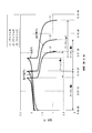
- a charge / discharge test of a redox flow battery having the configuration shown in FIG. 1 was performed.
- the redox flow battery used for the charge / discharge test is a small-scale battery for testing.
- GFA5 manufactured by SGL, which is a kind of carbon felt
- the electrode area was 10 cm 2 .
- Nafion 112 made by Daw which is a kind of ion exchange membrane
- SG carbon thickness 0.6 mm
- Showa Denko KK which is a kind of glassy carbon plate, was used as the current collector plate.
- a glass syringe (with the piston removed from the syringe) was used, and the positive electrode side and negative electrode side capacities (electrolytic solution capacities) in the state where the positive electrode, negative electrode, diaphragm, and current collector were loaded.
- the volume was adjusted to 5 ml.
- a glass syringe having a capacity of 10 ml (a piston having been omitted from a syringe having a capacity of 10 ml) was used.
- Silicone tubes were used as various pipes such as a supply pipe, a recovery pipe, an inert gas supply pipe, and an exhaust pipe.
- a micro tube pump MP-1000 manufactured by Tokyo Science Instrument Co., Ltd. was used as the pump.
- the charging / discharging battery test system PFX200 by Kikusui Electronics Industry Co., Ltd. was used as a charging / discharging apparatus.
- the conditions for the charge / discharge test were that both charging and discharging were performed at a constant current of 100 mA, the charge end voltage was set to 2.2V, and the discharge end voltage was set to 0.8V. And charging / discharging was repeated 3 times (3 cycles).
- nitrogen gas is supplied from an inert gas supply pipe to expel oxygen from the gas phase portion of the charge / discharge cell and the positive and negative electrolyte tanks. Expelled dissolved oxygen inside.
- the “charge / discharge cycle characteristics (reversibility)” is obtained by calculating the coulomb amount b during discharge in the second cycle charge / discharge and the coulomb amount e during discharge in the third cycle charge / discharge. b) ⁇ 100 ”(%). And the case where the calculated numerical value is 80% or more was evaluated as “ ⁇ ” (repetitive charge / discharge is possible), and the case where it is less than 80% was evaluated as “x” (repetitive charge / discharge is not possible).
- the “voltage efficiency” is obtained by calculating an average terminal voltage a at the time of charging in the second cycle charge / discharge and an average terminal voltage b at the time of discharging in the second cycle charging / discharging by the equation “(b / a)”. * 100 "(%).
- the above “utilization rate of the electrolytic solution” is obtained by multiplying the amount (mole number) of the active material of the electrolytic solution supplied to the positive electrode side or the negative electrode side by the Faraday constant (96500 coulomb / mol) to obtain the coulomb amount c.
- the coulomb amount d at the time of discharge in the charge / discharge of the cycle was obtained and calculated using the formula “(d / c) ⁇ 100” (%). If there is a difference between the amount of the active material of the electrolyte supplied to the positive electrode side and the amount of the active material of the electrolyte supplied to the negative electrode side in the so-called two-component system, the smaller amount is selected. It was decided to adopt and calculate.
- a negative electrode electrolyte was prepared by the following method. That is, first, 0.08 mol (40.0 g) of CrK (SO 4 ) 2 ⁇ 12H 2 O was added to 30 ml of distilled water and dissolved. Subsequently, 0.09 mol (26.3 g) of EDTA and 0.18 mol (7.2 g) of NaOH were added to the aqueous solution little by little and dissolved. The resulting aqueous solution was heated to reflux for 4 hours. During the reflux operation, 32 ml of NaOH aqueous solution having a concentration of 5.0 mol / L was added little by little. And after cooling aqueous solution, 0.2 mol (27.2g) sodium acetate trihydrate was added and dissolved.
- distilled water was added so that the total amount became 200 ml, and then diluted sulfuric acid having a concentration of 2.5 mol / L was added dropwise to adjust the pH to 5.7.
- an aqueous solution having a Cr-EDTA complex concentration of 0.4 mol / L was prepared and used as a negative electrode electrolyte.
- a positive electrode electrolyte was prepared by the following method. That is, first, 0.08 mol (13.5 g) of MnSO 4 .H 2 O was added to 140 ml of distilled water and dissolved. Subsequently, 0.08 mol (33.3 g) of EDTA.tetrasodium salt.dihydrate (EDTA (4Na) .2H 2 O) was added to this aqueous solution and dissolved, and then 0.2 mol. (16.4 g) of anhydrous sodium acetate was added and dissolved.
- distilled water was added so that the total amount became 200 ml, and then the pH was adjusted to 6.6 by dropwise addition of a 1.0 mol / L sodium acetate aqueous solution.
- an aqueous solution having a concentration of Mn-EDTA complex of 0.4 mol / L was prepared and used as a positive electrode electrolyte.
- the charge / discharge test of the redox flow battery used in Example 1 was performed using the positive electrode electrolyte and the negative electrode electrolyte.
- the conditions of the charge / discharge test were that both charging and discharging were performed at a constant current of 50 mA, the charge end voltage was set to 2.0V, and the discharge end voltage was set to 0.8V.
- the other conditions in the charge / discharge test were set to be the same as the conditions of the charge / discharge test in Example 1.
- electrolytic force is 1.85 V
- charge / discharge cycle characteristics (reversibility) is “ ⁇ ”
- Coulomb efficiency is 75%
- voltage efficiency is 85%
- energy efficiency is 64%.
- Ultraviolet efficiency of electrolytic solution was 55%. Therefore, it turned out that it can be used conveniently as a power storage battery.
- aqueous solutions were prepared by the following method so as to be a so-called one-component type. That is, in the same manner as in Example 2, an aqueous solution having a Cr-EDTA complex concentration of 0.4 mol / L and a pH of 5.7 was prepared. Next, after adding anhydrous sodium acetate and distilled water to the aqueous solution so that the concentration of Cr-EDTA complex is 0.1 mol / L and the concentration of sodium acetate is 1.0 mol / L, the concentration is The pH was adjusted to 5.5 by dropwise addition of 2.5 mol / L dilute sulfuric acid. As a result, a one-part electrolyte solution having a Cr-EDTA complex concentration of 0.1 mol / L was prepared.
- the charge / discharge test of the redox flow battery used in Example 1 was performed using the above electrolytic solution.
- the conditions of the charge / discharge test were that both charging and discharging were performed at a constant current of 50 mA, the charge end voltage was set to 2.4V, and the discharge end voltage was set to 0.8V.
- the other conditions in the charge / discharge test were set to be the same as the conditions of the charge / discharge test in Example 1.
- electrolytic force is 2.05 V
- charge / discharge cycle characteristics (reversibility) is “ ⁇ ”
- coulomb efficiency is 50%
- voltage efficiency is 60%
- energy efficiency is 30%.
- the “utilization rate of the electrolytic solution” was 10%, which proved unsuitable as a power storage battery.
- a positive electrode electrolyte was prepared by the following method. That is, first, 0.08 mol (22.2 g) of FeSO 4 .7H 2 O was added to 120 ml of distilled water and dissolved. Subsequently, 0.08 mol (29.8 g) of EDTA ⁇ disodium salt ⁇ dihydrate (EDTA (2Na) ⁇ 2H 2 O) was added to this aqueous solution and dissolved, and then 0.2 mol (16.4 g) of anhydrous sodium acetate was added and dissolved.
- 0.08 mol (22.2 g) of FeSO 4 .7H 2 O was added to 120 ml of distilled water and dissolved. Subsequently, 0.08 mol (29.8 g) of EDTA ⁇ disodium salt ⁇ dihydrate (EDTA (2Na) ⁇ 2H 2 O) was added to this aqueous solution and dissolved, and then 0.2 mol (16.4 g) of anhydrous sodium acetate was added and
- distilled water was added so that the total amount became 200 ml, and then an aqueous solution of sodium acetate having a concentration of 1.0 mol / L was added dropwise to adjust the pH to 4.5.
- an aqueous solution having a concentration of Fe-EDTA complex of 0.4 mol / L was prepared and used as a positive electrode electrolyte.
- the charge / discharge test of the redox flow battery used in Example 1 was performed using both the above electrolytes.
- the conditions of the charge / discharge test were that both charging and discharging were performed at a constant current of 50 mA, the charge end voltage was set to 1.6V, and the discharge end voltage was set to 0.8V.
- the other conditions in the charge / discharge test were set to be the same as the conditions of the charge / discharge test in Example 1.
- electrolytic force is 1.25 V
- charge / discharge cycle characteristics (reversibility) is “x”
- coulomb efficiency is 65%
- voltage efficiency is 90%
- energy efficiency is 59%.
- the “utilization rate of the electrolytic solution” was 25%, which proved unsuitable as a power storage battery.
- Example 3 In the same manner as in Example 2, an aqueous solution (pH: 5.7) having a Cr-EDTA complex concentration of 0.4 mol / L was prepared. On the other hand, an aqueous solution (pH 4.5) having a concentration of Fe-EDTA complex of 0.4 mol / L was prepared in the same manner as in Comparative Example 2. Then, by mixing the two aqueous solutions at a ratio of 1: 1, a premix type electrolytic solution in which the concentration of the Cr-EDTA complex is 0.2 mol / L and the concentration of the Fe-EDTA complex is 0.2 mol / L. A liquid was prepared.
- the charge / discharge test of the redox flow battery used in Example 1 was performed using the above electrolytic solution. As a result, the battery was charged with a constant current of 50 mA and the charge end voltage could be set to 1.3 V, but could not be discharged. Therefore, it turned out that it is unsuitable as a power storage battery.
- Example 4 In the same manner as in Example 2, an aqueous solution (pH: 5.7) having a Cr-EDTA complex concentration of 0.4 mol / L was prepared as a negative electrode electrolyte.
- a positive electrode electrolyte was prepared by the following method. That is, 0.08 mol (22.2 g) of FeSO 4 .7H 2 O was added to 90 ml of distilled water and dissolved, and then 80 ml of diluted sulfuric acid having a concentration of 2.5 mol / L was added. Next, the aqueous solution was diluted with distilled water to prepare an aqueous solution having a FeSO 4 concentration of 0.4 mol / L, which was used as a positive electrode electrolyte.
- the charge / discharge test of the redox flow battery used in Example 1 was performed using both the above electrolytes. As a result, the battery was charged with a constant current of 50 mA and the charge end voltage could be set to 1.3 V, but could not be discharged. Therefore, it turned out that it is unsuitable as a power storage battery.
- Example 5 In the same manner as in Example 2, an aqueous solution (pH: 5.7) having a Cr-EDTA complex concentration of 0.4 mol / L was prepared as a negative electrode electrolyte.
- a positive electrode electrolyte was prepared by the following method. That is, 0.2 mol (20.6 g) of NaBr was added and dissolved in 140 ml of distilled water, and then 0.2 mol (16.4 g) of anhydrous sodium acetate was added and dissolved. Then, distilled water was added so that the total amount was 200 ml. As a result, an aqueous solution having a NaBr concentration of 1.0 mol / L was prepared and used as a positive electrode electrolyte.
- the charge / discharge test of the redox flow battery used in Example 1 was performed using both the above electrolytes.
- the conditions of the charge / discharge test were that both charging and discharging were performed at a constant current of 50 mA, the charge end voltage was set to 2.3V, and the discharge end voltage was set to 0.8V.
- the other conditions in the charge / discharge test were set to be the same as the conditions of the charge / discharge test in Example 1.
- electrolytic force is 2.20 V
- charge / discharge cycle characteristics (reversibility) is “ ⁇ ”
- Coulomb efficiency is 55%
- voltage efficiency is 70%
- energy efficiency is 39%.
- the “utilization rate of the electrolytic solution” was 15%, which proved unsuitable as a power storage battery.
- aqueous solution having a Cr-EDTA complex concentration of 0.4 mol / L was prepared as a negative electrode electrolyte.
- a positive electrode electrolyte was prepared by the following method. That is, 0.2 mol (42.0 g) of tetraethylammonium bromide (N (C 2 H 5 ) 4 + ⁇ Br ⁇ ) was added to 130 ml of distilled water and dissolved, and then 0.2 mol (16. 4 g) anhydrous sodium acetate was added and dissolved. Then, distilled water was added so that the total amount was 200 ml. As a result, an aqueous solution having a tetraethylammonium bromide concentration of 1.0 mol / L was prepared and used as a positive electrode electrolyte.
- the charge / discharge test of the redox flow battery used in Example 1 was performed using both the above electrolytes.
- the conditions of the charge / discharge test were that both charging and discharging were performed at a constant current of 50 mA, the charge end voltage was set to 2.4V, and the discharge end voltage was set to 0.8V.
- the other conditions in the charge / discharge test were set to be the same as the conditions of the charge / discharge test in Example 1.
- electrolytic force is 2.15 V
- charge / discharge cycle characteristics (reversibility) is “x”
- coulomb efficiency is 40%
- voltage efficiency is 80%
- energy efficiency is 32%.
- the “utilization rate of the electrolytic solution” was 10%, which proved unsuitable as a power storage battery.
- Example 7 In the same manner as in Example 1, 140 ml of an aqueous solution (pH: 5.7) having a Cr-EDTA complex concentration of 0.57 mol / L was prepared. Next, the aqueous solution was diluted with distilled water so that the concentration of the Cr—EDTA complex was 0.4 mol / L, and 0.2 mol (20.6 g) of NaBr was added and dissolved. As a result, a one-component electrolyte solution having a Cr-EDTA complex concentration of 0.4 mol / L and a NaBr concentration of 1.0 mol / L was prepared.
- the charge / discharge test of the redox flow battery used in Example 1 was performed using the above electrolytic solution.
- the conditions of the charge / discharge test were that both charging and discharging were performed at a constant current of 50 mA, the charge end voltage was set to 2.3V, and the discharge end voltage was set to 0.8V.
- the other conditions in the charge / discharge test were set to be the same as the conditions of the charge / discharge test in Example 1.
- electrolytic force is 2.20 V
- charge / discharge cycle characteristics (reversibility) is “ ⁇ ”
- Coulomb efficiency is 45%
- voltage efficiency is 90%
- energy efficiency is 41%.
- the “utilization rate of the electrolytic solution” was 15%, which proved unsuitable as a power storage battery.
- Example 3 As the positive electrode electrolyte and the negative electrode electrolyte, an aqueous solution was prepared by the following method so as to be a so-called premix system. That is, first, in the same manner as in Example 1, 140 ml (pH: 5.7) of an aqueous solution having a Cr-EDTA complex concentration of 0.57 mol / L was prepared. Next, 0.1 mol (16.9 g) of MnSO 4 .H 2 O was added to the prepared aqueous solution and dissolved. Subsequently, 0.1 mol (41.6 g) of EDTA.tetrasodium salt.dihydrate (EDTA (4Na) .2H 2 O) was added and dissolved in this aqueous solution.
- EDTA EDTA.tetrasodium salt.dihydrate
- the charge / discharge test of the redox flow battery used in Example 1 was performed using the aqueous solution as a premix type electrolyte.
- the conditions of the charge / discharge test were that both charging and discharging were performed at a constant current of 100 mA, the charge end voltage was set to 2.2V, and the discharge end voltage was set to 0.8V.
- the other conditions in the charge / discharge test were set to be the same as the conditions of the charge / discharge test in Example 1.
- Example 4 As the positive electrode electrolyte and the negative electrode electrolyte, an aqueous solution was prepared by the following method so as to be a so-called premix system. That is, first, in the same manner as in Example 1, 105 ml of an aqueous solution (pH: 5.7) having a Cr-EDTA complex concentration of 0.57 mol / L was prepared. Next, 0.2 mol (33.8 g) of MnSO 4 .H 2 O was added to the prepared aqueous solution and dissolved. Subsequently, 0.2 mol (83.2 g) of EDTA.tetrasodium salt.dihydrate (EDTA (4Na) .2H 2 O) was added and dissolved in this aqueous solution.
- EDTA EDTA.tetrasodium salt.dihydrate
- the charge / discharge test of the redox flow battery used in Example 1 was performed using the aqueous solution as a premix type electrolyte.
- the conditions of the charge / discharge test were that both charging and discharging were performed at a constant current of 100 mA, the charge end voltage was set to 2.2V, and the discharge end voltage was set to 0.8V.
- the other conditions in the charge / discharge test were set to be the same as the conditions of the charge / discharge test in Example 1.
- electrolytic force is 2.0 V
- charge / discharge cycle characteristics (reversibility) is “ ⁇ ”
- Coulomb efficiency is 76%
- voltage efficiency is 70%
- energy efficiency is 53%.
- Ultraviolet intensity of electrolytic solution was 82%. Therefore, it turned out that it can be used conveniently as a power storage battery.
- Example 5 As the positive electrode electrolyte and the negative electrode electrolyte, an aqueous solution was prepared by the following method so as to be a so-called premix system. That is, in the same manner as in Example 3, an aqueous solution having a Mn-EDTA complex concentration of 0.4 mol / L and a Cr-EDTA complex concentration of 0.32 mol / L was prepared. Thereafter, dilute sulfuric acid having a concentration of 2.5 mol / L was dropped into this aqueous solution to adjust the pH to 3.0, thereby preparing a premix type electrolyte.
- the charge / discharge test of the redox flow battery used in Example 1 was performed using the above electrolytic solution.
- the charge / discharge test was conducted under the condition that both charging and discharging were performed at a constant current of 100 mA, the charge end voltage was set to 2.4V, and the discharge end voltage was set to 0.8V.
- the other conditions in the charge / discharge test were set to be the same as the conditions of the charge / discharge test in Example 1.
- electrolyte As a result, “electromotive force” is 2.0 V, “charge / discharge cycle characteristics (reversibility)” is “ ⁇ ”, “Coulomb efficiency” is 66%, “voltage efficiency” is 64%, and “energy efficiency” is 42%. “Utilization rate of electrolyte” was 29%. Therefore, it turned out that it can be used conveniently as a power storage battery.
- Example 6 A premix type electrolyte was prepared by performing the same operation as in Example 5 except that the pH was adjusted to 4.5.
- the charge / discharge test of the redox flow battery used in Example 1 was performed using the above electrolytic solution.
- the conditions of the charge / discharge test were that both charging and discharging were performed at a constant current of 100 mA, the charge end voltage was set to 2.2V, and the discharge end voltage was set to 0.8V.
- the other conditions in the charge / discharge test were set to be the same as the conditions of the charge / discharge test in Example 1.
- electrolytic solution As a result, “electromotive force” is 2.0 V, “charge / discharge cycle characteristics (reversibility)” is “ ⁇ ”, “Coulomb efficiency” is 74%, “voltage efficiency” is 70%, and “energy efficiency” is 52%.
- the “utilization rate of the electrolytic solution” was 39%. Therefore, it turned out that it can be used conveniently as a power storage battery.
- Example 7 As the positive electrode electrolyte and the negative electrode electrolyte, an aqueous solution was prepared by the following method so as to be a so-called premix system. That is, in the same manner as in Example 3, an aqueous solution having a Mn-EDTA complex concentration of 0.4 mol / L and a Cr-EDTA complex concentration of 0.32 mol / L was prepared. Thereafter, an aqueous NaOH solution having a concentration of 5.0 mol / L was dropped into this aqueous solution to adjust the pH to 6.0, thereby preparing a premix type electrolyte.
- the charge / discharge test of the redox flow battery used in Example 1 was performed using the above electrolytic solution.
- the conditions of the charge / discharge test were that both charging and discharging were performed at a constant current of 100 mA, the charge end voltage was set to 2.2V, and the discharge end voltage was set to 0.8V.
- the other conditions in the charge / discharge test were set to be the same as the conditions of the charge / discharge test in Example 1.
- electrolytic solution As a result, “electromotive force” is 2.0 V, “charge / discharge cycle characteristics (reversibility)” is “ ⁇ ”, “Coulomb efficiency” is 74%, “voltage efficiency” is 74%, and “energy efficiency” is 55%.
- the “utilization rate of the electrolytic solution” was 60%. Therefore, it turned out that it can be used conveniently as a power storage battery.
- Example 8 A premix type electrolyte was prepared by performing the same operation as in Example 7 except that the pH was adjusted to 8.0.
- the charge / discharge test of the redox flow battery used in Example 1 was performed using the above electrolytic solution.
- the conditions of the charge / discharge test were that charging and discharging were both performed at a constant current of 100 mA, the charge end voltage was set to 2.3V, and the discharge end voltage was set to 0.8V.
- the other conditions in the charge / discharge test were set to be the same as the conditions of the charge / discharge test in Example 1.
- electrolytic force is 2.0 V
- charge / discharge cycle characteristics (reversibility) is “ ⁇ ”
- Coulomb efficiency is 70%
- voltage efficiency is 68%
- energy efficiency is 48%.
- Ultraviolet intensity of electrolytic solution was 43%. Therefore, it turned out that it can be used conveniently as a power storage battery.
- the power storage battery of the present invention it is possible to provide a power storage battery that is excellent in handleability and excellent in various performances such as charge / discharge cycle characteristics (reversibility), energy efficiency, and coulomb efficiency at a relatively low cost. There is an effect that can be.
- the power storage battery according to the present invention can be widely used not only in power companies but also in various industries that require power storage.
- Redox flow battery power storage battery
- Charge / discharge cell battery container
- Positive electrode side cell 2b
- Negative electrode side cell 3
- Positive electrode electrolyte tank 4
- Negative electrode electrolyte tank 10
- Separator 12 Current collector plate 13
- Positive electrode 14 Current collector plate 15
Landscapes
- Life Sciences & Earth Sciences (AREA)
- Engineering & Computer Science (AREA)
- Manufacturing & Machinery (AREA)
- Sustainable Development (AREA)
- Sustainable Energy (AREA)
- Chemical & Material Sciences (AREA)
- Chemical Kinetics & Catalysis (AREA)
- Electrochemistry (AREA)
- General Chemical & Material Sciences (AREA)
- Fuel Cell (AREA)
Abstract
L'invention concerne un accumulateur de type redox (1) comprenant principalement un élément de chargement/déchargement (2), une cuve de solution électrolytique pour électrode positive (3) et une cuve de solution électrolytique pour électrode négative (4). L'intérieur de l'élément de chargement/déchargement (2) est partagé en un élément du côté de l'électrode positive (c'est-à-dire un élément côté électrode positive) (2a) et un élément du côté de l'électrode négative (c'est-à-dire un élément côté électrode négative) (2b) par un film de séparation (11) comprenant un film échangeur d'ions ou similaire. Dans l'élément côté électrode positive (2a) se trouvent une plaque collectrice de courant (12) telle qu'une plaque de carbone vitreux et une électrode positive (13) comprenant un feutre de carbone ou similaire. Dans l'électrode positive (13), une solution aqueuse contenant un complexe Mn-EDTA et ayant une valeur de pH de 3 à 8 est fournie par la cuve de solution électrolytique pour électrode positive (3) par une conduite d'alimentation (3a). De cette manière, il devient possible de fournir un accumulateur de type redox (1) ayant d'excellentes caractéristiques de fonctionnement et d'excellentes propriétés, notamment des propriétés de cycle de chargement et de déchargement, d'efficacité énergétique et d'efficacité de Coulomb, pour un coût relativement bas.
Priority Applications (2)
| Application Number | Priority Date | Filing Date | Title |
|---|---|---|---|
| PCT/JP2011/054798 WO2012117543A1 (fr) | 2011-03-02 | 2011-03-02 | Accumulateur électrique |
| PCT/JP2011/070367 WO2012117594A1 (fr) | 2011-03-02 | 2011-09-07 | Batterie de stockage électrique |
Applications Claiming Priority (1)
| Application Number | Priority Date | Filing Date | Title |
|---|---|---|---|
| PCT/JP2011/054798 WO2012117543A1 (fr) | 2011-03-02 | 2011-03-02 | Accumulateur électrique |
Publications (1)
| Publication Number | Publication Date |
|---|---|
| WO2012117543A1 true WO2012117543A1 (fr) | 2012-09-07 |
Family
ID=46757503
Family Applications (2)
| Application Number | Title | Priority Date | Filing Date |
|---|---|---|---|
| PCT/JP2011/054798 Ceased WO2012117543A1 (fr) | 2011-03-02 | 2011-03-02 | Accumulateur électrique |
| PCT/JP2011/070367 Ceased WO2012117594A1 (fr) | 2011-03-02 | 2011-09-07 | Batterie de stockage électrique |
Family Applications After (1)
| Application Number | Title | Priority Date | Filing Date |
|---|---|---|---|
| PCT/JP2011/070367 Ceased WO2012117594A1 (fr) | 2011-03-02 | 2011-09-07 | Batterie de stockage électrique |
Country Status (1)
| Country | Link |
|---|---|
| WO (2) | WO2012117543A1 (fr) |
Cited By (12)
| Publication number | Priority date | Publication date | Assignee | Title |
|---|---|---|---|---|
| US20140028261A1 (en) * | 2012-07-27 | 2014-01-30 | Sun Catalytic Corporation | Electrochemical Energy Storage Systems and Methods Featuring Large Negative Half-Cell Potentials |
| WO2014102910A1 (fr) * | 2012-12-25 | 2014-07-03 | 日新電機 株式会社 | Batterie de stockage d'électricité |
| WO2014102898A1 (fr) * | 2012-12-25 | 2014-07-03 | 日新電機 株式会社 | Batterie de stockage d'électricité |
| WO2014147778A1 (fr) * | 2013-03-21 | 2014-09-25 | 日新電機 株式会社 | Batterie de stockage d'énergie électrique |
| JP2015065157A (ja) * | 2013-08-26 | 2015-04-09 | 一般社団法人新エネルギー支援機構 | 電力エネルギーの輸送システム |
| EP3174149A4 (fr) * | 2014-07-25 | 2017-07-12 | Sumitomo Electric Industries, Ltd. | Batterie de type à circulation de solution électrolytique |
| US9768463B2 (en) | 2012-07-27 | 2017-09-19 | Lockheed Martin Advanced Energy Storage, Llc | Aqueous redox flow batteries comprising metal ligand coordination compounds |
| US9865893B2 (en) | 2012-07-27 | 2018-01-09 | Lockheed Martin Advanced Energy Storage, Llc | Electrochemical energy storage systems and methods featuring optimal membrane systems |
| US9899694B2 (en) | 2012-07-27 | 2018-02-20 | Lockheed Martin Advanced Energy Storage, Llc | Electrochemical energy storage systems and methods featuring high open circuit potential |
| CN114899466A (zh) * | 2022-06-21 | 2022-08-12 | 中山大学 | 一种锰铁液流电池及其制造方法 |
| WO2023227226A1 (fr) * | 2022-05-27 | 2023-11-30 | Green Energy Storage S.R.L. | Batterie redox |
| CN120709391A (zh) * | 2025-08-27 | 2025-09-26 | 杭州德海艾科能源科技有限公司 | 一种尖晶石纳米纤维复合石墨毡电极及其制备方法 |
Families Citing this family (5)
| Publication number | Priority date | Publication date | Assignee | Title |
|---|---|---|---|---|
| JP2016177868A (ja) * | 2013-08-07 | 2016-10-06 | 住友電気工業株式会社 | レドックスフロー電池 |
| CN107134582B (zh) * | 2017-06-05 | 2021-04-06 | 上海骐杰碳素材料有限公司 | 一种高活性电极材料及其改性方法 |
| MX2020001819A (es) | 2017-08-17 | 2020-09-25 | Univ Columbia | Baterias de flujo redox y compuestos para aplicacion de bateria. |
| JP2022525563A (ja) | 2019-03-20 | 2022-05-17 | ザ リージェンツ オブ ザ ユニバーシティ オブ コロラド,ア ボディー コーポレイト | キレート化金属を含む電気化学貯蔵装置 |
| CN114243073B (zh) * | 2021-12-09 | 2023-11-28 | 大连融科储能集团股份有限公司 | 一种低温下稳定运行和存储的盐酸电解液、其制备方法及应用 |
Citations (6)
| Publication number | Priority date | Publication date | Assignee | Title |
|---|---|---|---|---|
| JPS579073A (en) * | 1980-06-17 | 1982-01-18 | Agency Of Ind Science & Technol | Bedox battery |
| JPS579072A (en) * | 1980-06-17 | 1982-01-18 | Agency Of Ind Science & Technol | Redox battery |
| JPS611270U (ja) * | 1984-06-11 | 1986-01-07 | 住友電気工業株式会社 | 電池 |
| JPS6122574A (ja) * | 1984-07-09 | 1986-01-31 | Sumitomo Electric Ind Ltd | 電池 |
| JP2002193621A (ja) * | 2000-12-26 | 2002-07-10 | Nippon Chem Ind Co Ltd | 変性バナジウム化合物、その製造方法、レドックスフロー型電池用電解液組成物及びレドックスフロー型電池用電解液の製造方法 |
| JP2009231230A (ja) * | 2008-03-25 | 2009-10-08 | Kurita Water Ind Ltd | 微生物発電方法および装置 |
Family Cites Families (2)
| Publication number | Priority date | Publication date | Assignee | Title |
|---|---|---|---|---|
| JPS5834911B2 (ja) * | 1979-09-14 | 1983-07-29 | 工業技術院長 | レドツクス電池 |
| JPS6215770A (ja) * | 1985-07-11 | 1987-01-24 | Yamaguchi Univ | レドックス二次電池 |
-
2011
- 2011-03-02 WO PCT/JP2011/054798 patent/WO2012117543A1/fr not_active Ceased
- 2011-09-07 WO PCT/JP2011/070367 patent/WO2012117594A1/fr not_active Ceased
Patent Citations (6)
| Publication number | Priority date | Publication date | Assignee | Title |
|---|---|---|---|---|
| JPS579073A (en) * | 1980-06-17 | 1982-01-18 | Agency Of Ind Science & Technol | Bedox battery |
| JPS579072A (en) * | 1980-06-17 | 1982-01-18 | Agency Of Ind Science & Technol | Redox battery |
| JPS611270U (ja) * | 1984-06-11 | 1986-01-07 | 住友電気工業株式会社 | 電池 |
| JPS6122574A (ja) * | 1984-07-09 | 1986-01-31 | Sumitomo Electric Ind Ltd | 電池 |
| JP2002193621A (ja) * | 2000-12-26 | 2002-07-10 | Nippon Chem Ind Co Ltd | 変性バナジウム化合物、その製造方法、レドックスフロー型電池用電解液組成物及びレドックスフロー型電池用電解液の製造方法 |
| JP2009231230A (ja) * | 2008-03-25 | 2009-10-08 | Kurita Water Ind Ltd | 微生物発電方法および装置 |
Cited By (25)
| Publication number | Priority date | Publication date | Assignee | Title |
|---|---|---|---|---|
| US9559374B2 (en) * | 2012-07-27 | 2017-01-31 | Lockheed Martin Advanced Energy Storage, Llc | Electrochemical energy storage systems and methods featuring large negative half-cell potentials |
| US10707513B2 (en) | 2012-07-27 | 2020-07-07 | Lockheed Martin Energy, Llc | Aqueous redox flow batteries comprising metal ligand coordination compounds |
| US10651489B2 (en) | 2012-07-27 | 2020-05-12 | Lockheed Martin Energy, Llc | Electrochemical energy storage systems and methods featuring optimal membrane systems |
| US10483581B2 (en) | 2012-07-27 | 2019-11-19 | Lockheed Martin Energy, Llc | Electrochemical energy storage systems and methods featuring large negative half-cell potentials |
| US9899694B2 (en) | 2012-07-27 | 2018-02-20 | Lockheed Martin Advanced Energy Storage, Llc | Electrochemical energy storage systems and methods featuring high open circuit potential |
| US9865893B2 (en) | 2012-07-27 | 2018-01-09 | Lockheed Martin Advanced Energy Storage, Llc | Electrochemical energy storage systems and methods featuring optimal membrane systems |
| US20140028261A1 (en) * | 2012-07-27 | 2014-01-30 | Sun Catalytic Corporation | Electrochemical Energy Storage Systems and Methods Featuring Large Negative Half-Cell Potentials |
| US9768463B2 (en) | 2012-07-27 | 2017-09-19 | Lockheed Martin Advanced Energy Storage, Llc | Aqueous redox flow batteries comprising metal ligand coordination compounds |
| US9515345B2 (en) | 2012-12-25 | 2016-12-06 | Nissin Electric Co., Ltd. | Electricity-storage battery |
| WO2014102898A1 (fr) * | 2012-12-25 | 2014-07-03 | 日新電機 株式会社 | Batterie de stockage d'électricité |
| JPWO2014102898A1 (ja) * | 2012-12-25 | 2017-01-12 | 日新電機株式会社 | 電力貯蔵電池及びその製造方法 |
| WO2014102910A1 (fr) * | 2012-12-25 | 2014-07-03 | 日新電機 株式会社 | Batterie de stockage d'électricité |
| JPWO2014102910A1 (ja) * | 2012-12-25 | 2017-01-12 | 日新電機株式会社 | 電力貯蔵電池及びその製造方法 |
| US9774054B2 (en) | 2013-03-21 | 2017-09-26 | Nissin Electric Co., Ltd. | Electricity storage battery |
| JP6065351B2 (ja) * | 2013-03-21 | 2017-01-25 | 日新電機株式会社 | 電力貯蔵電池 |
| WO2014147778A1 (fr) * | 2013-03-21 | 2014-09-25 | 日新電機 株式会社 | Batterie de stockage d'énergie électrique |
| CN105493329B (zh) * | 2013-08-26 | 2017-03-01 | 一般社团法人新能源支援机构 | 电力能量的输送系统 |
| CN105493329A (zh) * | 2013-08-26 | 2016-04-13 | 一般社团法人新能源支援机构 | 电力能量的输送系统 |
| JP2015065157A (ja) * | 2013-08-26 | 2015-04-09 | 一般社団法人新エネルギー支援機構 | 電力エネルギーの輸送システム |
| US10396372B2 (en) | 2014-07-25 | 2019-08-27 | Sumitomo Electric Industries, Ltd. | Electrolytic solution circulation type battery |
| EP3174149A4 (fr) * | 2014-07-25 | 2017-07-12 | Sumitomo Electric Industries, Ltd. | Batterie de type à circulation de solution électrolytique |
| WO2023227226A1 (fr) * | 2022-05-27 | 2023-11-30 | Green Energy Storage S.R.L. | Batterie redox |
| CN114899466A (zh) * | 2022-06-21 | 2022-08-12 | 中山大学 | 一种锰铁液流电池及其制造方法 |
| CN114899466B (zh) * | 2022-06-21 | 2023-02-21 | 中山大学 | 一种锰铁液流电池及其制造方法 |
| CN120709391A (zh) * | 2025-08-27 | 2025-09-26 | 杭州德海艾科能源科技有限公司 | 一种尖晶石纳米纤维复合石墨毡电极及其制备方法 |
Also Published As
| Publication number | Publication date |
|---|---|
| WO2012117594A1 (fr) | 2012-09-07 |
Similar Documents
| Publication | Publication Date | Title |
|---|---|---|
| WO2012117543A1 (fr) | Accumulateur électrique | |
| CN111354965B (zh) | 一种大规模储能低成本中性液流电池的制备方法 | |
| CN118016944B (zh) | 一种水系铁铈液流电池 | |
| CN104995767B (zh) | 包含金属配体配位化合物的含水氧化还原液流电池 | |
| CN111509278B (zh) | 一种在线恢复全钒液流电池容量及效率的方法 | |
| CN101997129B (zh) | 一种液流电池 | |
| JP5768933B2 (ja) | 電力貯蔵電池 | |
| JP7035181B2 (ja) | 亜鉛-ヨウ化物フロー電池 | |
| JP4911357B2 (ja) | 水素貯蔵タンクを有する燃料電池 | |
| CN108475802A (zh) | 再生燃料电池 | |
| CN104716304A (zh) | 一种锌镍双液液流电池 | |
| CN105680082A (zh) | 一种长寿命锌溴液流电池结构及其电解液 | |
| WO2014207923A1 (fr) | Accumulateur à flux redox | |
| CN103872370B (zh) | 液流电池 | |
| CN106030884A (zh) | 氧化还原液流电池 | |
| CN113013460B (zh) | 一种碱性锌铁液流电池用负极电解液及锌铁液流电池 | |
| CN102544563A (zh) | 一种锌沉积型液流储能电池系统及其运行方式 | |
| CN117219821A (zh) | 一种铬-稀土液流电池 | |
| CN114824369B (zh) | 一种全铁液流电池的电解液再平衡方法 | |
| CN103794813B (zh) | 铕铈液流电池 | |
| CN104335405A (zh) | 蓄电池 | |
| CN119324241B (zh) | 一种新型铕铈液流电池电解液及制备方法 | |
| CN108123174A (zh) | 一种碱性锌铁液流电池用正极电解液及应用 | |
| CN106129443B (zh) | 一种新型的keggin型钴钨酸液流电池 | |
| JP6220462B2 (ja) | 化学流動電池の運転方法 |
Legal Events
| Date | Code | Title | Description |
|---|---|---|---|
| 121 | Ep: the epo has been informed by wipo that ep was designated in this application |
Ref document number: 11860051 Country of ref document: EP Kind code of ref document: A1 |
|
| NENP | Non-entry into the national phase |
Ref country code: DE |
|
| 122 | Ep: pct application non-entry in european phase |
Ref document number: 11860051 Country of ref document: EP Kind code of ref document: A1 |
|
| NENP | Non-entry into the national phase |
Ref country code: JP |