WO2012117559A1 - 太陽電池モジュ-ル用裏面側保護シ-トおよび太陽電池モジュ-ル - Google Patents
太陽電池モジュ-ル用裏面側保護シ-トおよび太陽電池モジュ-ル Download PDFInfo
- Publication number
- WO2012117559A1 WO2012117559A1 PCT/JP2011/054960 JP2011054960W WO2012117559A1 WO 2012117559 A1 WO2012117559 A1 WO 2012117559A1 JP 2011054960 W JP2011054960 W JP 2011054960W WO 2012117559 A1 WO2012117559 A1 WO 2012117559A1
- Authority
- WO
- WIPO (PCT)
- Prior art keywords
- solar cell
- cell module
- protective sheet
- side protective
- metal foil
- Prior art date
- Legal status (The legal status is an assumption and is not a legal conclusion. Google has not performed a legal analysis and makes no representation as to the accuracy of the status listed.)
- Ceased
Links
Images




Classifications
-
- B—PERFORMING OPERATIONS; TRANSPORTING
- B32—LAYERED PRODUCTS
- B32B—LAYERED PRODUCTS, i.e. PRODUCTS BUILT-UP OF STRATA OF FLAT OR NON-FLAT, e.g. CELLULAR OR HONEYCOMB, FORM
- B32B15/00—Layered products comprising a layer of metal
- B32B15/04—Layered products comprising a layer of metal comprising metal as the main or only constituent of a layer, which is next to another layer of the same or of a different material
- B32B15/08—Layered products comprising a layer of metal comprising metal as the main or only constituent of a layer, which is next to another layer of the same or of a different material of synthetic resin
-
- B—PERFORMING OPERATIONS; TRANSPORTING
- B32—LAYERED PRODUCTS
- B32B—LAYERED PRODUCTS, i.e. PRODUCTS BUILT-UP OF STRATA OF FLAT OR NON-FLAT, e.g. CELLULAR OR HONEYCOMB, FORM
- B32B15/00—Layered products comprising a layer of metal
- B32B15/18—Layered products comprising a layer of metal comprising iron or steel
-
- B—PERFORMING OPERATIONS; TRANSPORTING
- B32—LAYERED PRODUCTS
- B32B—LAYERED PRODUCTS, i.e. PRODUCTS BUILT-UP OF STRATA OF FLAT OR NON-FLAT, e.g. CELLULAR OR HONEYCOMB, FORM
- B32B17/00—Layered products essentially comprising sheet glass, or glass, slag, or like fibres
- B32B17/06—Layered products essentially comprising sheet glass, or glass, slag, or like fibres comprising glass as the main or only constituent of a layer, next to another layer of a specific material
- B32B17/10—Layered products essentially comprising sheet glass, or glass, slag, or like fibres comprising glass as the main or only constituent of a layer, next to another layer of a specific material of synthetic resin
- B32B17/10005—Layered products essentially comprising sheet glass, or glass, slag, or like fibres comprising glass as the main or only constituent of a layer, next to another layer of a specific material of synthetic resin laminated safety glass or glazing
- B32B17/10009—Layered products essentially comprising sheet glass, or glass, slag, or like fibres comprising glass as the main or only constituent of a layer, next to another layer of a specific material of synthetic resin laminated safety glass or glazing characterized by the number, the constitution or treatment of glass sheets
- B32B17/10018—Layered products essentially comprising sheet glass, or glass, slag, or like fibres comprising glass as the main or only constituent of a layer, next to another layer of a specific material of synthetic resin laminated safety glass or glazing characterized by the number, the constitution or treatment of glass sheets comprising only one glass sheet
-
- B—PERFORMING OPERATIONS; TRANSPORTING
- B32—LAYERED PRODUCTS
- B32B—LAYERED PRODUCTS, i.e. PRODUCTS BUILT-UP OF STRATA OF FLAT OR NON-FLAT, e.g. CELLULAR OR HONEYCOMB, FORM
- B32B17/00—Layered products essentially comprising sheet glass, or glass, slag, or like fibres
- B32B17/06—Layered products essentially comprising sheet glass, or glass, slag, or like fibres comprising glass as the main or only constituent of a layer, next to another layer of a specific material
- B32B17/10—Layered products essentially comprising sheet glass, or glass, slag, or like fibres comprising glass as the main or only constituent of a layer, next to another layer of a specific material of synthetic resin
- B32B17/10005—Layered products essentially comprising sheet glass, or glass, slag, or like fibres comprising glass as the main or only constituent of a layer, next to another layer of a specific material of synthetic resin laminated safety glass or glazing
- B32B17/1055—Layered products essentially comprising sheet glass, or glass, slag, or like fibres comprising glass as the main or only constituent of a layer, next to another layer of a specific material of synthetic resin laminated safety glass or glazing characterized by the resin layer, i.e. interlayer
- B32B17/10788—Layered products essentially comprising sheet glass, or glass, slag, or like fibres comprising glass as the main or only constituent of a layer, next to another layer of a specific material of synthetic resin laminated safety glass or glazing characterized by the resin layer, i.e. interlayer containing ethylene vinylacetate
-
- B—PERFORMING OPERATIONS; TRANSPORTING
- B32—LAYERED PRODUCTS
- B32B—LAYERED PRODUCTS, i.e. PRODUCTS BUILT-UP OF STRATA OF FLAT OR NON-FLAT, e.g. CELLULAR OR HONEYCOMB, FORM
- B32B27/00—Layered products comprising a layer of synthetic resin
- B32B27/30—Layered products comprising a layer of synthetic resin comprising vinyl (co)polymers; comprising acrylic (co)polymers
- B32B27/306—Layered products comprising a layer of synthetic resin comprising vinyl (co)polymers; comprising acrylic (co)polymers comprising vinyl acetate or vinyl alcohol (co)polymers
-
- H—ELECTRICITY
- H10—SEMICONDUCTOR DEVICES; ELECTRIC SOLID-STATE DEVICES NOT OTHERWISE PROVIDED FOR
- H10F—INORGANIC SEMICONDUCTOR DEVICES SENSITIVE TO INFRARED RADIATION, LIGHT, ELECTROMAGNETIC RADIATION OF SHORTER WAVELENGTH OR CORPUSCULAR RADIATION
- H10F19/00—Integrated devices, or assemblies of multiple devices, comprising at least one photovoltaic cell covered by group H10F10/00, e.g. photovoltaic modules
- H10F19/80—Encapsulations or containers for integrated devices, or assemblies of multiple devices, having photovoltaic cells
- H10F19/85—Protective back sheets
-
- B—PERFORMING OPERATIONS; TRANSPORTING
- B32—LAYERED PRODUCTS
- B32B—LAYERED PRODUCTS, i.e. PRODUCTS BUILT-UP OF STRATA OF FLAT OR NON-FLAT, e.g. CELLULAR OR HONEYCOMB, FORM
- B32B2327/00—Polyvinylhalogenides
- B32B2327/12—Polyvinylhalogenides containing fluorine
-
- B—PERFORMING OPERATIONS; TRANSPORTING
- B32—LAYERED PRODUCTS
- B32B—LAYERED PRODUCTS, i.e. PRODUCTS BUILT-UP OF STRATA OF FLAT OR NON-FLAT, e.g. CELLULAR OR HONEYCOMB, FORM
- B32B2367/00—Polyesters, e.g. PET, i.e. polyethylene terephthalate
-
- B—PERFORMING OPERATIONS; TRANSPORTING
- B32—LAYERED PRODUCTS
- B32B—LAYERED PRODUCTS, i.e. PRODUCTS BUILT-UP OF STRATA OF FLAT OR NON-FLAT, e.g. CELLULAR OR HONEYCOMB, FORM
- B32B2457/00—Electrical equipment
- B32B2457/12—Photovoltaic modules
-
- Y—GENERAL TAGGING OF NEW TECHNOLOGICAL DEVELOPMENTS; GENERAL TAGGING OF CROSS-SECTIONAL TECHNOLOGIES SPANNING OVER SEVERAL SECTIONS OF THE IPC; TECHNICAL SUBJECTS COVERED BY FORMER USPC CROSS-REFERENCE ART COLLECTIONS [XRACs] AND DIGESTS
- Y02—TECHNOLOGIES OR APPLICATIONS FOR MITIGATION OR ADAPTATION AGAINST CLIMATE CHANGE
- Y02B—CLIMATE CHANGE MITIGATION TECHNOLOGIES RELATED TO BUILDINGS, e.g. HOUSING, HOUSE APPLIANCES OR RELATED END-USER APPLICATIONS
- Y02B10/00—Integration of renewable energy sources in buildings
- Y02B10/10—Photovoltaic [PV]
-
- Y—GENERAL TAGGING OF NEW TECHNOLOGICAL DEVELOPMENTS; GENERAL TAGGING OF CROSS-SECTIONAL TECHNOLOGIES SPANNING OVER SEVERAL SECTIONS OF THE IPC; TECHNICAL SUBJECTS COVERED BY FORMER USPC CROSS-REFERENCE ART COLLECTIONS [XRACs] AND DIGESTS
- Y02—TECHNOLOGIES OR APPLICATIONS FOR MITIGATION OR ADAPTATION AGAINST CLIMATE CHANGE
- Y02E—REDUCTION OF GREENHOUSE GAS [GHG] EMISSIONS, RELATED TO ENERGY GENERATION, TRANSMISSION OR DISTRIBUTION
- Y02E10/00—Energy generation through renewable energy sources
- Y02E10/50—Photovoltaic [PV] energy
Definitions
- the present invention relates to a back side protection sheet for a solar cell module and a solar cell module.
- a solar cell module includes a packing layer for fixing a solar cell array with a filler (sealing material), and a surface protection sheet for a solar cell module (hereinafter referred to as a surface side) laminated on the sunlight incident side of the packing layer. And a back surface protection sheet for a solar cell module (hereinafter referred to as a back surface protection sheet) laminated on the surface opposite to the sunlight incident side of the filling layer.
- the back surface side protective sheet is a resin made of a metal foil such as iron or aluminum, or a resin such as polyethylene terephthalate (PET) in order to improve barrier properties against water or gas and weather resistance.
- PET polyethylene terephthalate
- a back surface side protection sheet in which resin films are laminated on both surfaces of a metal foil is used (for example, see Patent Document 1).
- the solar cell module since the solar cell module is installed outdoors for a long period of 10 years or more in actual use, it is subjected to temperature cycle stress.
- a metal foil such as iron or aluminum is used for the back side protection sheet
- the expansion and contraction force of the metal foil due to the temperature cycle is larger than that of the front side protection sheet generally using glass or the like.
- the temperature cycle stress on the sealed solar cell array increases.
- the present invention has been made in view of the above, and is provided with a solar cell module back surface protection sheet that is excellent in weather resistance and barrier properties and can suppress temperature cycle stress, and the solar cell module.
- An object of the present invention is to obtain a highly reliable solar cell module using the
- the back side protective sheet for solar cell module is provided with a sealing material between the front side protective sheet and the back side protective sheet having translucency.
- a back side protection sheet for a solar cell module used for a solar cell module formed by sealing a solar cell, and has a smaller linear expansion coefficient than the front side protection sheet and extends in the surface direction of the sealing material. It is characterized by comprising an arranged metal foil.
- a solar cell module back surface protection sheet that is excellent in weather resistance and barrier properties in a solar cell module and can suppress temperature cycle stress.
- FIG. 1-1 is a cross-sectional view schematically showing a schematic configuration of the solar cell module according to Embodiment 1 of the present invention.
- FIG. 1-2 is a main part sectional view schematically showing the configuration of the solar cell array according to the first embodiment of the present invention.
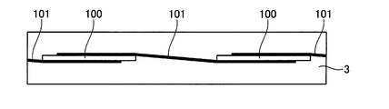
- FIGS. 1-3 is a principal part top view which shows typically the state which looked at the solar cell array concerning Embodiment 1 of this invention from the light-receiving surface side.
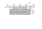
- FIG. 2 is a cross-sectional view schematically illustrating the state of the solar cell module when the temperature is lowered.
- FIG. 3 is a cross-sectional view schematically explaining the state of the solar cell module when the temperature rises.
- FIG. 1-1 is a cross-sectional view schematically showing a schematic configuration of the solar cell module according to Embodiment 1 of the present invention.
- FIG. 1-2 is a main part sectional view schematically showing the configuration of the solar cell array according to the first embodiment of the present invention.
- FIG. 4 is a cross-sectional view schematically showing a schematic configuration of the solar cell module according to Embodiment 2 of the present invention.
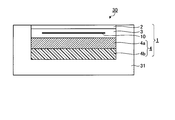
- FIG. 5 is sectional drawing which shows typically schematic structure of the roof material type solar cell module concerning Embodiment 3 of this invention.
- FIG. 1-1 is a cross-sectional view schematically showing a schematic configuration of the solar cell module according to Embodiment 1 of the present invention.
- the solar cell module 1 according to the first embodiment includes a solar cell array 10 (hereinafter referred to as array 10) in which a plurality of solar cells 100 (hereinafter referred to as cells 100) are electrically connected. Called).
- FIG. 1-2 is a main part sectional view schematically showing a configuration of the array 10 according to the first exemplary embodiment of the present invention.
- FIG. 1-3 is a plan view of a principal part schematically showing a state in which the array 10 according to the first embodiment of the present invention is viewed from the light receiving surface side.
- the module 1 includes a solar cell module surface side protective sheet 2 (hereinafter referred to as a surface side protective sheet 2), which is a solar cell module surface side protective member disposed on the surface side (light incident side) of the module 1.
- the back side protection sheet 4 for the solar cell module which is a back side protection member for the solar cell module disposed on the back side (opposite to the light incident side) of the module 1 (hereinafter referred to as back side protection sheet). (Referred to as 4) is sandwiched between the fillers (sealing materials) 3.
- An array 10 is sealed in the filler (sealing material) 3.
- An aluminum frame member 6 is attached to the side surface of the module 1 via a sealing material (not shown).
- the surface side protection sheet 2 protects the array 10 sealed with the filler (sealing material) 3.
- the surface-side protective sheet 2 is made of a light-transmitting material, and for example, glass or a resin plate is used. In this embodiment, the case where glass is used will be described.
- the surface side protective sheet 2 is fixed to the outer surface of the filler 3 located on the light receiving surface side of the module 1.
- a light-transmitting resin such as ethylene-vinyl acetate copolymer (EVA) is used as ethylene-vinyl acetate copolymer (EVA) is used.
- the back surface side protection sheet 4 protects the array 10 sealed with the filler (sealing material) 3.
- a metal foil layer 4a and a resin film layer 4b are laminated in this order from the filler (sealing material) 3 side.
- the back surface side protection sheet 4 is fixed to the outer surface of the filler 3 located on the installation surface side of the module 1.
- the metal foil layer 4a is arranged to extend in the surface direction of the filler (sealing material) 3 in order to enhance the barrier property and weather resistance against moisture and gas.
- the surface side protective sheet 2 is made of a material having a lower linear expansion coefficient than the material used for 2.
- the metal foil layer 4a is made of, for example, an invar (63.5Fe-36.5Ni) metal foil (hereinafter referred to as an invar foil).
- Use metal foil of super invar (63Fe-32Ni-5Co) hereinafter referred to as super invar foil
- metal foil of stainless invar (Fe-54Co-9.5Cr) hereinafter referred to as stainless invar foil
- the linear expansion coefficient of the white sheet glass having a small Fe component generally used for the surface side protective sheet 2 is 9 [ ⁇ 10 ⁇ 6 / ° C.]
- the linear expansion coefficient of the invar foil is 1.2 [ ⁇ 10 ⁇ 6 / ° C.]
- the coefficient of linear expansion of Super Invar foil is 0.5 [ ⁇ 10 ⁇ 6 / ° C.]
- the coefficient of linear expansion of Stainless Invar foil is 0.1 [ ⁇ 10 ⁇ 6 / ° C.].
- the resin film layer 4b is made of a resin such as polyethylene terephthalate (PET) or polyvinyl fluoride (Po1y Vinyl Fluoride: PVF).
- the back surface side protective sheet 4 is formed by laminating a metal foil layer 4a and a resin film layer 4b.
- a method of laminating the metal foil layer 4a and the resin film layer 4b a known method may be used.
- a dry laminating method using an adhesive is a method of bonding a plurality of films using an adhesive.
- the co-extrusion method is a technique in which a plurality of materials are extruded and overlapped at a time in the melt extrusion molding method.
- Examples of the adhesive used in the dry laminating method include a two-component curable urethane adhesive, a polyether urethane adhesive, a polyester adhesive, a polyester polyol adhesive, and a polyester polyurethane polyol adhesive.
- the array 10 is packaged with a plurality of cells 100 separated by a predetermined distance in the in-plane direction of the filler (sealing material) 3. Adjacent cells 100 are electrically connected by an inter-element connection line 101. For example, a conductive wire is used as the inter-element connection line 101.
- FIGS. 1-2 and 1-3 show the module 10 packaged with two cells 100, but the number of cells 100 is not limited to this, and a large number of cells 100 are not limited thereto. It can comprise.
- a known solar cell such as a crystal system can be used.
- crystalline solar cells include, but are not limited to, single crystal silicon solar cells and polycrystalline silicon solar cells.
- a method for manufacturing the module 1 will be described.
- a plurality of cells 100 are manufactured by a known method.
- the array 10 is produced using the cells 100.
- the array 10 is produced by arranging a plurality of cells 100 at a predetermined distance and electrically connecting adjacent cells 100 with inter-element connection lines 101.
- the surface side protective sheet 2 made of glass, the filler 3 made of EVA resin or the like, the array 10, the filler 3, and the back side protective sheet 4 are stacked in this order, Heat press in vacuum. As a result, the surface side protection sheet 2 to the back side protection sheet 4 are integrated by the filler 3 to complete the module 1.
- FIG. 2 is a cross-sectional view schematically illustrating the state of the module 1 when the temperature decreases.
- the surface side protection sheet 2 contracts due to the temperature decrease.
- a stress F1 in a shrinking direction acts on the filler (sealing material) 3, and the filler (sealing material) 3 shrinks.
- the invar foil which is the metal foil layer 4a of the back surface side protective sheet 4
- the glass which is the front surface side protective sheet 2
- the shrinkage due to the temperature drop is smaller than that of the glass.
- the filler (sealing material) 3 in contact with the invar foil is subjected to a stress F2 in the direction in which the filler (sealing material) 3 expands. ) 3 contraction is suppressed.
- FIG. 3 is a cross-sectional view schematically illustrating the state of the module 1 when the temperature rises.
- the filler (sealing material) 3 has a stress F3 in the expanding direction as the surface side protective sheet 2 expands due to the temperature rise. Inflate.
- the Invar foil which is the metal foil layer 4a of the back surface side protective sheet 4
- the glass which is the front surface side protective sheet 2
- the filler (sealing material) 3 in contact with the invar foil is subjected to a stress F4 in a direction in which the filler (sealing material) 3 contracts to suppress the expansion of the sealing material.
- the temperature cycle stress on the array 10 sealed in the filler (sealing material) 3 is suppressed to be small, and the elements in the array 10 are caused by the temperature cycle stress.
- the disconnection of the connection line 101 and the occurrence of cracks in the cell 100 are suppressed.
- the module 1 has a long service life.
- the back surface side protection sheet 4 includes the metal foil layer 4a made of a material having a lower linear expansion coefficient than the material used for the front surface side protection sheet 2.
- the metal foil layer 4a made of a material having a lower linear expansion coefficient than the material used for the front surface side protection sheet 2.
- FIG. FIG. 4 is a cross-sectional view schematically showing a schematic configuration of the solar cell module according to the second embodiment.
- the solar cell module according to the second embodiment is different from the module 1 according to the first embodiment described above in that the back surface side protection sheet includes three layers. That is, the solar cell module 20 according to the second embodiment (hereinafter referred to as the module 20) is a surface-side protection sheet that is a surface-side protection member for a solar cell module disposed on the surface side (light incident side) of the module 20.
- the sheet 2 and the back side protection sheet 5 for the solar cell module (hereinafter referred to as the back side protection sheet 5) disposed on the back side of the module 1 (the side opposite to the light incident side);
- the filler (sealing material) 3 and the array 10 are sandwiched.
- symbol is abbreviate
- the back surface side protection sheet 5 protects the array 10 sealed with the filler (sealing material) 3.
- a first resin film layer 5a, a metal foil layer 5b, and a second resin film layer 5c are laminated in this order from the filler (sealing material) 3 side.
- the first resin film layer 5a is made of a resin such as polyethylene terephthalate (PET) or polyvinyl fluoride (PVF).
- the metal foil layer 5b is used to increase the barrier property and weather resistance against moisture and gas, and in this embodiment, is made of a material having a lower linear expansion coefficient than the material used for the surface side protective sheet 2.
- the metal foil layer 5b is made of, for example, invar (63.5Fe-36.5Ni) metal foil, super invar (63Fe-32Ni— 5Co) metal foil, stainless steel invar (Fe-54Co-9.5Cr) metal foil, or the like can be used.
- the second resin film layer 5c is made of a resin such as polyethylene terephthalate (PET) or polyvinyl fluoride (PVF).
- the filler (sealing material) 3 is provided by including the metal foil layer 5b. Temperature cycle stress on the array 10 sealed inside is suppressed to a small level, and disconnection of the inter-element connection lines 101 in the array 10 and generation of cracks in the cell 100 are suppressed due to the temperature cycle stress. As a result, the module 20 has a long service life.
- the back surface side protection sheet 4 includes the metal foil layer 5b made of a material having a lower linear expansion coefficient than the material used for the front surface side protection sheet 2.
- the metal foil layer 5b made of a material having a lower linear expansion coefficient than the material used for the front surface side protection sheet 2.
- FIG. FIG. 5 is a cross-sectional view schematically showing a schematic configuration of the roofing solar cell module according to the third embodiment.
- a solar cell module 30 (hereinafter referred to as a module 30) according to the third embodiment is a roof material integrated solar cell module in which a solar cell module and a roof material body are integrated. That is, the module 30 has a configuration in which the module 1 and the roof material body 31 are fixed by an adhesive or the like. Therefore, since the module 30 includes the module 1 to which the present invention is applied, as in the case of the first embodiment, a solar cell module having excellent weather resistance and barrier properties and excellent reliability is realized.
- the solar cell module of the roof material type or the roof material integrated type has little cooling effect due to ventilation, and the temperature of the solar cell module itself becomes high, so that the temperature cycle stress is large. For this reason, a temperature cycle stress is large compared with a roof-standing type or a flat roof type solar cell module, and high temperature cycle suppression performance is required. Therefore, in the solar cell module 30 according to the third embodiment, temperature cycle suppression by providing the metal foil layer 4a is particularly effective.
- the back surface protection sheet for a solar cell module according to the present invention is useful for realizing weather resistance, barrier properties, and suppression of temperature cycle stress in the solar cell module.
Landscapes
- Photovoltaic Devices (AREA)
Abstract
透光性を有する表面側保護シートと裏面側保護シートとの間に封止材により太陽電池を封止してなる太陽電池モジュールに用いられる太陽電池モジュール用裏面側保護シート4であって、前記表面側保護シート2よりも線膨張係数が小さく前記封止材3の面方向に延在して配置された金属箔4aを備えることにより、太陽電池モジュール1における耐候性、バリア性に優れ、温度サイクルストレスを抑制することが可能な太陽電池モジュール用裏面側保護シ-ト4を実現する。
Description
本発明は、太陽電池モジュ-ル用裏面側保護シ-トおよび太陽電池モジュ-ルに関する。
太陽電池モジュールは、充填材(封止材)により太陽電池アレイを固定する充填層と、該充填層の太陽光入射側に積層される太陽電池モジュール用表面側保護シ-ト(以下、表面側保護シ-トと呼ぶ)と、該充填層の太陽光入射側と反対面側に積層される太陽電池モジュール用裏面側保護シ-ト(以下、裏面側保護シ-トと呼ぶ)とを備えている。ここで、裏面側保護シ-トは、水分やガスに対するバリア性や耐候性を高める為に、鉄やアルミニウムなどの金属箔や、ポリエチレンテレフタレート(Polyethylene Terephthalate:PET)等の樹脂で構成された樹脂シートを積層したものが使用される。
たとえば、屋根材と一体化された屋根材型太陽電池モジュールでは、金属箔の両面に樹脂フィルムを積層した裏面側保護シ-トが用いられている(たとえば、特許文献1参照)。
しかしながら、太陽電池モジュールは、実使用において10年以上の長期間にわたって屋外に設置される為、温度サイクルストレスを受ける。そして、裏面側保護シ-トに鉄やアルミニウムなどの金属箔を用いた場合は、温度サイクルによる金属箔の膨張収縮力が、一般的にガラス等が用いられる表面側保護シ-トよりも大きく、封止された太陽電池アレイに対する温度サイクルストレスが大きくなる。
このため、太陽電池モジュールの設置環境や太陽電池モジュールを構成する材料の種類によっては、温度サイクルストレスに起因して、内部配線の断線や、封止された太陽電池セルにおいてクラックが発生する、という問題があった。
本発明は、上記に鑑みてなされたものであって、太陽電池モジュールにおける耐候性、バリア性に優れ、温度サイクルストレスを抑制することが可能な太陽電池モジュール用裏面側保護シ-ト、およびこれを使用した信頼性に優れる太陽電池モジュールを得ることを目的とする。
上述した課題を解決し、目的を達成するために、本発明にかかる太陽電池モジュール用裏面側保護シートは、透光性を有する表面側保護シートと裏面側保護シートとの間に封止材により太陽電池を封止してなる太陽電池モジュールに用いられる太陽電池モジュール用裏面側保護シートであって、前記表面側保護シートよりも線膨張係数が小さく前記封止材の面方向に延在して配置された金属箔を備えること、を特徴とする。
本発明によれば、太陽電池モジュールにおける耐候性、バリア性に優れ、温度サイクルストレスを抑制することが可能な太陽電池モジュール用裏面側保護シ-トが得られる、という効果を奏する。
以下に、本発明にかかる太陽電池モジュ-ル用裏面側保護シ-トおよび太陽電池モジュ-ルの実施の形態を図面に基づいて詳細に説明する。なお、本発明は以下の記述に限定されるものではなく、本発明の要旨を逸脱しない範囲において適宜変更可能である。また、以下に示す図面においては、理解の容易のため、各部材の縮尺が実際とは異なる場合がある。各図面間においても同様である。
実施の形態1.
図1-1は、本発明の実施の形態1にかかる太陽電池モジュールの概略構成を模式的に示す断面図である。実施の形態1にかかる太陽電池モジュール1(以下、モジュール1と呼ぶ)は、複数の太陽電池セル100(以下、セル100と呼ぶ)が電気的に接続された太陽電池アレイ10(以下、アレイ10と呼ぶ)を有する。図1-2は、本発明の実施の形態1にかかるアレイ10の構成を模式的に示す要部断面図である。図1-3は、本発明の実施の形態1にかかるアレイ10を受光面側から見た状態を模式的に示す要部平面図である。
図1-1は、本発明の実施の形態1にかかる太陽電池モジュールの概略構成を模式的に示す断面図である。実施の形態1にかかる太陽電池モジュール1(以下、モジュール1と呼ぶ)は、複数の太陽電池セル100(以下、セル100と呼ぶ)が電気的に接続された太陽電池アレイ10(以下、アレイ10と呼ぶ)を有する。図1-2は、本発明の実施の形態1にかかるアレイ10の構成を模式的に示す要部断面図である。図1-3は、本発明の実施の形態1にかかるアレイ10を受光面側から見た状態を模式的に示す要部平面図である。
まず、図1-1を参照してモジュール1の構成を説明する。モジュール1は、モジュール1の表面側(光入射側)に配置された太陽電池モジュール用表面側保護部材である太陽電池モジュール用表面側保護シ-ト2(以下、表面側保護シ-ト2と呼ぶ)とモジュール1の裏面側(光入射側と反対側)に配置された太陽電池モジュール用裏面側保護部材である太陽電池モジュール用裏面側保護シ-ト4(以下、裏面側保護シ-ト4と呼ぶ)との間に、充填材(封止材)3が狭持されている。そして、充填材(封止材)3の中にはアレイ10が封止されている。なお、モジュール1の側面には、アルミニウム製枠部材6がシール材(図示せず)を介して取り付けられている。
表面側保護シ-ト2は、充填材(封止材)3に封止されたアレイ10を保護する。表面側保護シ-ト2は、透光性を有する材料からなり、例えばガラスや樹脂板などが用いられる。本実施の形態では、ガラスを用いる場合について説明する。表面側保護シ-ト2は、モジュール1の受光面側に位置する充填材3の外表面に固着されている。充填材(封止材)3は、例えばエチレン-酢酸ビニル共重合体(EVA)等の透光性を有する樹脂が用いられる。
裏面側保護シ-ト4は、充填材(封止材)3に封止されたアレイ10を保護する。裏面側保護シ-ト4は、充填材(封止材)3側から金属箔層4aと樹脂フィルム層4bとがこの順で積層されている。裏面側保護シ-ト4は、モジュール1の設置面側に位置する充填材3の外表面に固着されている。
金属箔層4aは、水分やガスに対するバリア性や耐候性を高める為に充填材(封止材)3の面方向に延在して配置され、本実施の形態では、表面側保護シ-ト2に用いられる材料よりも線膨張係数が低い材料からなる。表面側保護シ-ト2が、一般的に用いられるガラスからなる場合には、金属箔層4aには例えば、インバー(63.5Fe-36.5Ni)の金属箔(以下、インバー箔と呼ぶ)、スーパーインバー(63Fe-32Ni-5Co)の金属箔(以下、スーパーインバー箔と呼ぶ)、ステンレスインバー(Fe-54Co-9.5Cr)の金属箔(以下、ステンレスインバー箔と呼ぶ)等を用いることができる。ここで、一般的に表面側保護シ-ト2に用いられるFe成分の少ない白板ガラスの線膨張係数は9[×10-6/℃]、インバー箔の線膨張係数は1.2[×10-6/℃]、スーパーインバー箔の線膨張係数は0.5[×10-6/℃]、ステンレスインバー箔の線膨張係数は0.1[×10-6/℃]である。本実施の形態では、金属箔層4aとしてインバー箔を用いる場合について説明する。樹脂フィルム層4bは、例えばポリエチレンテレフタレート(PET)やポリフッ化ビニル(Po1y Vinyl Fluoride:PVF)などの樹脂からなる。
裏面側保護シ-ト4は、金属箔層4aと樹脂フィルム層4bとを積層して形成する。金属箔層4aと樹脂フィルム層4bとの積層方法は、公知の方法を用いればよく、たとえば、接着剤を使用したドライラミネート法、共押出し法、押出しコート法、アンカーコート剤を用いた熱ラミネート法などを用いることができる。接着剤を使用したドライラミネート法は、複数のフィルムを接着剤を使用して貼り合わせる手法である。また、共押出法は、融押出成型法において、複数の素材を一度に押し出して重ねる手法である。
ドライラミネート法に用いる接着剤としては、例えば2液硬化型ウレタン系接着剤、ポリエーテルウレタン系接着剤、ポリエステル系接着剤、ポリエステルポリオール系接着剤、ポリエステルポリウレタンポリオール系接着剤などが挙げられる。特に、芳香族イソシアネートまたは脂肪族イソシアネートの少なくとも1種を含むウレタン系接着剤を用いてドライラミネート法により積層することが好ましい。
つぎに、図1-2および図1-3を参照してアレイ10の構成について説明する。アレイ10は、複数のセル100が、充填材(封止材)3の面内方向において所定の距離だけ離間してパッケージされている。隣接するセル100同士は、素子間接続線101により電気的に接続されている。素子間接続線101には、例えば導線が用いられる。なお、図1-2および図1-3においては、2つのセル100を備えてパッケージされたモジュール10を示しているが、セル100の数量はこれに限定されるものではなく、多数のセル100を備えて構成することができる。
セル100としては、例えば結晶系等の公知の太陽電池セルを用いることができる。結晶系太陽電池セルとしては、例えば単結晶シリコン太陽電池セル、多結晶シリコン太陽電池セルなどが挙げられるが、これに限定されるものではない。
つぎに、モジュール1の製造方法について説明する。まず、公知の方法により複数のセル100を作製する。つぎに、セル100を用いてアレイ10を作製する。アレイ10は、複数のセル100を所定の距離を離して配置し、隣接するセル100同士を素子間接続線101により電気的に接続することにより作製する。つぎに、ガラスからなる表面側保護シ-ト2上に、EVA樹脂等からなる充填材3、アレイ10、充填材3、裏面側保護シ-ト4をこの順で重ねた後、これらを例えば真空中で加熱プレスする。これにより、表面側保護シ-ト2から裏面側保護シ-ト4までが充填材3により一体化し、モジュール1が完成する。
図2は、温度が低下する場合のモジュール1の状態を模式的に説明する断面図である。以上のように構成された実施の形態1にかかるモジュール1では、外部環境の温度低下などによりモジュール1の温度が低下する場合には、温度低下による表面側保護シ-ト2の収縮に伴って充填材(封止材)3には収縮する方向の応力F1が働き、充填材(封止材)3が収縮する。
このとき、裏面側保護シ-ト4の金属箔層4aであるインバー箔は、表面側保護シ-ト2であるガラスよりも線膨張係数が低いため、温度低下による収縮量はガラスよりも小さくなる。そして、この収縮量の差に起因して、インバー箔に接する充填材(封止材)3には充填材(封止材)3を膨張する方向の応力F2が働き、充填材(封止材)3の収縮を抑制する。
図3は、温度が上昇する場合のモジュール1の状態を模式的に説明する断面図である。外部環境の温度上昇などによりモジュール1の温度が上昇する場合には、温度上昇による表面側保護シ-ト2の膨張に伴って充填材(封止材)3には膨張する方向の応力F3が膨張する。
このとき、裏面側保護シ-ト4の金属箔層4aであるインバー箔は、表面側保護シ-ト2であるガラスよりも線膨張係数が低いため、温度上昇による膨張量はガラスよりも小さくなる。そして、この膨張量の差に起因して、インバー箔に接する充填材(封止材)3には充填材(封止材)3を収縮する方向の応力F4が働き封止材の膨張を抑制する。
これにより、実施の形態1にかかるモジュール1では、充填材(封止材)3内に封止されたアレイ10に対する温度サイクルストレスが小さく抑制され、温度サイクルストレスに起因してアレイ10における素子間接続線101の断線やセル100におけるクラックの発生が抑制される。この結果、モジュール1では、長寿命化が実現されている。
したがって、実施の形態1にかかるモジュール1によれば、裏面側保護シ-ト4が表面側保護シ-ト2に用いられる材料よりも線膨張係数が低い材料からなる金属箔層4aを備えることにより、耐候性、バリア性に優れ、信頼性に優れた太陽電池モジュールが実現される。
実施の形態2.
図4は、実施の形態2にかかる太陽電池モジュールの概略構成を模式的に示す断面図である。実施の形態2にかかる太陽電池モジュールは、裏面側保護シ-トが3層からなることが上述した実施の形態1にかかるモジュール1と異なる。すなわち、実施の形態2にかかる太陽電池モジュール20(以下、モジュール20と呼ぶ)は、モジュール20の表面側(光入射側)に配置された太陽電池モジュール用表面側保護部材である表面側保護シ-ト2とモジュール1の裏面側(光入射側と反対側)に配置された太陽電池モジュール用裏面側保護シ-ト5(以下、裏面側保護シ-ト5と呼ぶ)との間に、充填材(封止材)3、アレイ10が狭持されている。なお、実施の形態1にかかるモジュール1と同じ部材については、同じ符号を付すことで詳細な説明は省略する。
図4は、実施の形態2にかかる太陽電池モジュールの概略構成を模式的に示す断面図である。実施の形態2にかかる太陽電池モジュールは、裏面側保護シ-トが3層からなることが上述した実施の形態1にかかるモジュール1と異なる。すなわち、実施の形態2にかかる太陽電池モジュール20(以下、モジュール20と呼ぶ)は、モジュール20の表面側(光入射側)に配置された太陽電池モジュール用表面側保護部材である表面側保護シ-ト2とモジュール1の裏面側(光入射側と反対側)に配置された太陽電池モジュール用裏面側保護シ-ト5(以下、裏面側保護シ-ト5と呼ぶ)との間に、充填材(封止材)3、アレイ10が狭持されている。なお、実施の形態1にかかるモジュール1と同じ部材については、同じ符号を付すことで詳細な説明は省略する。
裏面側保護シ-ト5は、充填材(封止材)3に封止されたアレイ10を保護する。裏面側保護シ-ト5は、充填材(封止材)3側から第1の樹脂フィルム層5aと金属箔層5bと第2の樹脂フィルム層5cとがこの順で積層されている。第1の樹脂フィルム層5aは、例えばポリエチレンテレフタレート(PET)やポリフッ化ビニル(PVF)などの樹脂からなる。
金属箔層5bは、水分やガスに対するバリア性や耐候性を高める為に用いられ、本実施の形態では、表面側保護シ-ト2に用いられる材料よりも線膨張係数が低い材料からなる。表面側保護シ-ト2が、一般的に用いられるガラスからなる場合には、金属箔層5bには例えば、インバー(63.5Fe-36.5Ni)の金属箔、スーパーインバー(63Fe-32Ni-5Co)の金属箔、ステンレスインバー(Fe-54Co-9.5Cr)の金属箔等を用いることができる。第2の樹脂フィルム層5cは、例えばポリエチレンテレフタレート(PET)やポリフッ化ビニル(PVF)などの樹脂からなる。
以上のように構成された実施の形態2にかかるモジュール20においても、上述した実施の形態1にかかるモジュール1の場合と同様に、金属箔層5bを備えることにより充填材(封止材)3内に封止されたアレイ10に対する温度サイクルストレスが小さく抑制され、温度サイクルストレスに起因してアレイ10における素子間接続線101の断線やセル100におけるクラックの発生が抑制される。この結果、モジュール20では、長寿命化が実現されている。
したがって、実施の形態2にかかるモジュール1によれば、裏面側保護シ-ト4が表面側保護シ-ト2に用いられる材料よりも線膨張係数が低い材料からなる金属箔層5bを備えることにより、耐候性、バリア性に優れ、信頼性に優れた太陽電池モジュールが実現される。
実施の形態3.
図5は、実施の形態3にかかる屋根材型太陽電池モジュールの概略構成を模式的に示す断面図である。実施の形態3にかかる太陽電池モジュール30(以下、モジュール30と呼ぶ)は、太陽電池モジュールと屋根材本体とが一体とされた屋根材一体型太陽電池モジュールである。すなわち、モジュール30は、モジュール1と、屋根材本体31とが接着剤等により固定された構成を有する。したがって、モジュール30は、本発明を適用したモジュール1を有するため、実施の形態1の場合と同様に耐候性、バリア性に優れ、信頼性に優れた太陽電池モジュールが実現されている。
図5は、実施の形態3にかかる屋根材型太陽電池モジュールの概略構成を模式的に示す断面図である。実施の形態3にかかる太陽電池モジュール30(以下、モジュール30と呼ぶ)は、太陽電池モジュールと屋根材本体とが一体とされた屋根材一体型太陽電池モジュールである。すなわち、モジュール30は、モジュール1と、屋根材本体31とが接着剤等により固定された構成を有する。したがって、モジュール30は、本発明を適用したモジュール1を有するため、実施の形態1の場合と同様に耐候性、バリア性に優れ、信頼性に優れた太陽電池モジュールが実現されている。
ここで、屋根材型や屋根材一体型の太陽電池モジュールは、通風による冷却効果が少なく、太陽電池モジュール自体の温度が高温になるため、温度サイクルストレスが大きい。この為、温度サイクルストレスは、屋根置き型や陸屋根型太陽電池モジュールと比較して大きく、高い温度サイクル抑制性能が必要となる。したがって、実施の形態3にかかる太陽電池モジュール30においては、金属箔層4aを備えることによる温度サイクル抑制が特に有効である。
以上のように、本発明にかかる太陽電池モジュール用裏面側保護シ-トは、太陽電池モジュールにおける耐候性、バリア性および温度サイクルストレスの抑制の実現に有用である。
1 太陽電池モジュール(モジュール)
2 太陽電池モジュール用表面側保護シ-ト(表面側保護シ-ト)
3 充填材(封止材)
4 太陽電池モジュール用裏面側保護シ-ト(裏面側保護シ-ト)
4a 金属箔層
4b 樹脂フィルム層
5 太陽電池モジュール用裏面側保護シ-ト(裏面側保護シ-ト)
5a 樹脂フィルム層
5b 金属箔層
5c 樹脂フィルム層
6 アルミニウム製枠部材
10 太陽電池アレイ(アレイ)
20 太陽電池モジュール(モジュール)
30 太陽電池モジュール(モジュール)
31 屋根材本体
100 太陽電池セル(セル)
101 素子間接続線
F1 収縮する方向の応力
F2 膨張する方向の応力
F3 膨張する方向の応力
F4 収縮する方向の応力
2 太陽電池モジュール用表面側保護シ-ト(表面側保護シ-ト)
3 充填材(封止材)
4 太陽電池モジュール用裏面側保護シ-ト(裏面側保護シ-ト)
4a 金属箔層
4b 樹脂フィルム層
5 太陽電池モジュール用裏面側保護シ-ト(裏面側保護シ-ト)
5a 樹脂フィルム層
5b 金属箔層
5c 樹脂フィルム層
6 アルミニウム製枠部材
10 太陽電池アレイ(アレイ)
20 太陽電池モジュール(モジュール)
30 太陽電池モジュール(モジュール)
31 屋根材本体
100 太陽電池セル(セル)
101 素子間接続線
F1 収縮する方向の応力
F2 膨張する方向の応力
F3 膨張する方向の応力
F4 収縮する方向の応力
Claims (11)
- 透光性を有する表面側保護シートと裏面側保護シートとの間に封止材により太陽電池を封止してなる太陽電池モジュールに用いられる太陽電池モジュール用裏面側保護シートであって、
前記表面側保護シートよりも線膨張係数が小さく前記封止材の面方向に延在して配置された金属箔を備えること、
を特徴とする太陽電池モジュール用裏面側保護シート。 - 前記金属箔と樹脂層とが積層されてなること、
を特徴とする請求項1に記載の太陽電池モジュール用裏面側保護シート。 - 前記表面側保護シートがガラスからなり、前記金属箔がインバー箔であること、
を特徴とする請求項1または2に記載の太陽電池モジュール用裏面側保護シート。 - 前記表面側保護シートがガラスからなり、前記金属箔がスーパーインバー箔であること、
を特徴とする請求項1または2に記載の太陽電池モジュール用裏面側保護シート。 - 前記表面側保護シートがガラスからなり、前記金属箔がステンレスインバー箔であること、
を特徴とする請求項1または2に記載の太陽電池モジュール用裏面側保護シート。 - 透光性を有する表面側保護シートと裏面側保護シートとの間に封止材により太陽電池を封止してなる太陽電池モジュールであって、
前記裏面側保護シートが、前記表面側保護シートよりも線膨張係数が小さく前記封止材の面方向に延在して配置された金属箔を備えること、
を特徴とする太陽電池モジュール。 - 前記金属箔と樹脂層とが積層されてなること、
を特徴とする請求項6に記載の太陽電池モジュール。 - 前記表面側保護シートがガラスからなり、前記金属箔がインバー箔であること、
を特徴とする請求項6または7に記載の太陽電池モジュール。 - 前記表面側保護シートがガラスからなり、前記金属箔がスーパーインバー箔であること、
を特徴とする請求項6または7に記載の太陽電池モジュール。 - 前記表面側保護シートがガラスからなり、前記金属箔がステンレスインバー箔であること、
を特徴とする請求項6または7に記載の太陽電池モジュール。 - 屋根材本体に固定されて一体化されていること、
を特徴とする請求項6~10のいずれか1つに記載の太陽電池モジュール。
Priority Applications (1)
| Application Number | Priority Date | Filing Date | Title |
|---|---|---|---|
| PCT/JP2011/054960 WO2012117559A1 (ja) | 2011-03-03 | 2011-03-03 | 太陽電池モジュ-ル用裏面側保護シ-トおよび太陽電池モジュ-ル |
Applications Claiming Priority (1)
| Application Number | Priority Date | Filing Date | Title |
|---|---|---|---|
| PCT/JP2011/054960 WO2012117559A1 (ja) | 2011-03-03 | 2011-03-03 | 太陽電池モジュ-ル用裏面側保護シ-トおよび太陽電池モジュ-ル |
Publications (1)
| Publication Number | Publication Date |
|---|---|
| WO2012117559A1 true WO2012117559A1 (ja) | 2012-09-07 |
Family
ID=46757518
Family Applications (1)
| Application Number | Title | Priority Date | Filing Date |
|---|---|---|---|
| PCT/JP2011/054960 Ceased WO2012117559A1 (ja) | 2011-03-03 | 2011-03-03 | 太陽電池モジュ-ル用裏面側保護シ-トおよび太陽電池モジュ-ル |
Country Status (1)
| Country | Link |
|---|---|
| WO (1) | WO2012117559A1 (ja) |
Cited By (1)
| Publication number | Priority date | Publication date | Assignee | Title |
|---|---|---|---|---|
| DE102016109748A1 (de) * | 2016-05-26 | 2017-11-30 | Masdar Pv Gmbh | Photovoltaikmodul und Verfahren zu dessen Herstellung |
Citations (5)
| Publication number | Priority date | Publication date | Assignee | Title |
|---|---|---|---|---|
| JPS6122627U (ja) * | 1984-07-13 | 1986-02-10 | 凸版印刷株式会社 | シ−ト材料 |
| JP2000345675A (ja) * | 1999-03-26 | 2000-12-12 | Canon Inc | 太陽電池モジュール、太陽電池付き屋根、及び太陽電池発電システム |
| JP2003251765A (ja) * | 2002-02-27 | 2003-09-09 | Dengiken:Kk | 電気・電子絶縁シート |
| JP2007268710A (ja) * | 2006-03-30 | 2007-10-18 | Teijin Dupont Films Japan Ltd | 太陽電池裏面保護膜用ポリエステルフィルムおよびそれを用いた太陽電池裏面保護膜 |
| JP2010034275A (ja) * | 2008-07-29 | 2010-02-12 | Toyo Aluminium Kk | 太陽電池モジュール用裏面保護シート |
-
2011
- 2011-03-03 WO PCT/JP2011/054960 patent/WO2012117559A1/ja not_active Ceased
Patent Citations (5)
| Publication number | Priority date | Publication date | Assignee | Title |
|---|---|---|---|---|
| JPS6122627U (ja) * | 1984-07-13 | 1986-02-10 | 凸版印刷株式会社 | シ−ト材料 |
| JP2000345675A (ja) * | 1999-03-26 | 2000-12-12 | Canon Inc | 太陽電池モジュール、太陽電池付き屋根、及び太陽電池発電システム |
| JP2003251765A (ja) * | 2002-02-27 | 2003-09-09 | Dengiken:Kk | 電気・電子絶縁シート |
| JP2007268710A (ja) * | 2006-03-30 | 2007-10-18 | Teijin Dupont Films Japan Ltd | 太陽電池裏面保護膜用ポリエステルフィルムおよびそれを用いた太陽電池裏面保護膜 |
| JP2010034275A (ja) * | 2008-07-29 | 2010-02-12 | Toyo Aluminium Kk | 太陽電池モジュール用裏面保護シート |
Cited By (1)
| Publication number | Priority date | Publication date | Assignee | Title |
|---|---|---|---|---|
| DE102016109748A1 (de) * | 2016-05-26 | 2017-11-30 | Masdar Pv Gmbh | Photovoltaikmodul und Verfahren zu dessen Herstellung |
Similar Documents
| Publication | Publication Date | Title |
|---|---|---|
| US7960643B2 (en) | Isolated metallic flexible back sheet for solar module encapsulation | |
| US7829783B2 (en) | Isolated metallic flexible back sheet for solar module encapsulation | |
| JP5902711B2 (ja) | 改良された光起電力装置 | |
| JP5367230B2 (ja) | 太陽電池モジュール | |
| JP7408573B2 (ja) | ポリマーからなる前部層と複合材料からなる後部層を含む軽量かつフレキシブルな太陽電池モジュール | |
| US20110139224A1 (en) | Oriented reinforcement for frameless solar modules | |
| US20140137940A1 (en) | Solar cell module and method of manufacturing same | |
| US20110214716A1 (en) | Isolated metallic flexible back sheet for solar module encapsulation | |
| US20140137939A1 (en) | Solar-cell module and manufacturing method therefor | |
| US11784268B2 (en) | Flexible and light photovoltaic module | |
| JP5506295B2 (ja) | 太陽電池モジュールおよびその製造方法 | |
| EP3363052B1 (en) | Forming front metal contact on solar cell with enhanced resistance to stress | |
| CN103168416B (zh) | 可挠性的建筑整合式光伏打结构 | |
| US20180358494A1 (en) | Photovoltaic module comprising a polymer layer provided with recesses forming expansion joints | |
| KR102730921B1 (ko) | 건물 부착형 고경량 유연성 슁글드 태양광 모듈 구조 | |
| JP2009200145A (ja) | 太陽電池バックシート及び太陽電池モジュール | |
| WO2012117559A1 (ja) | 太陽電池モジュ-ル用裏面側保護シ-トおよび太陽電池モジュ-ル | |
| JP6661051B2 (ja) | 太陽電池モジュールおよび太陽電池モジュールの製造方法 | |
| JP2012102587A (ja) | 太陽電池一体型屋根材 | |
| JP4550390B2 (ja) | 太陽電池モジュール | |
| JP2009170771A (ja) | 太陽電池バックシート及び太陽電池モジュール | |
| JP5643440B2 (ja) | 改良された光起電装置 | |
| JP2016213264A (ja) | 太陽電池モジュール | |
| US20250176281A1 (en) | Solar module | |
| JP2012038778A (ja) | 太陽電池モジュール及びその製造方法 |
Legal Events
| Date | Code | Title | Description |
|---|---|---|---|
| 121 | Ep: the epo has been informed by wipo that ep was designated in this application |
Ref document number: 11860013 Country of ref document: EP Kind code of ref document: A1 |
|
| NENP | Non-entry into the national phase |
Ref country code: DE |
|
| 122 | Ep: pct application non-entry in european phase |
Ref document number: 11860013 Country of ref document: EP Kind code of ref document: A1 |
|
| NENP | Non-entry into the national phase |
Ref country code: JP |