WO2012117581A1 - 竹製ボード及び複合ボード並びにそれらの製造方法 - Google Patents
竹製ボード及び複合ボード並びにそれらの製造方法 Download PDFInfo
- Publication number
- WO2012117581A1 WO2012117581A1 PCT/JP2011/067206 JP2011067206W WO2012117581A1 WO 2012117581 A1 WO2012117581 A1 WO 2012117581A1 JP 2011067206 W JP2011067206 W JP 2011067206W WO 2012117581 A1 WO2012117581 A1 WO 2012117581A1
- Authority
- WO
- WIPO (PCT)
- Prior art keywords
- bamboo
- adhesive
- board
- cutting
- rectangular tube
- Prior art date
- Legal status (The legal status is an assumption and is not a legal conclusion. Google has not performed a legal analysis and makes no representation as to the accuracy of the status listed.)
- Ceased
Links
Images






Classifications
-
- B—PERFORMING OPERATIONS; TRANSPORTING
- B27—WORKING OR PRESERVING WOOD OR SIMILAR MATERIAL; NAILING OR STAPLING MACHINES IN GENERAL
- B27N—MANUFACTURE BY DRY PROCESSES OF ARTICLES, WITH OR WITHOUT ORGANIC BINDING AGENTS, MADE FROM PARTICLES OR FIBRES CONSISTING OF WOOD OR OTHER LIGNOCELLULOSIC OR LIKE ORGANIC MATERIAL
- B27N3/00—Manufacture of substantially flat articles, e.g. boards, from particles or fibres
- B27N3/06—Making particle boards or fibreboards, with preformed covering layers, the particles or fibres being compressed with the layers to a board in one single pressing operation
-
- B—PERFORMING OPERATIONS; TRANSPORTING
- B27—WORKING OR PRESERVING WOOD OR SIMILAR MATERIAL; NAILING OR STAPLING MACHINES IN GENERAL
- B27D—WORKING VENEER OR PLYWOOD
- B27D1/00—Joining wood veneer with any material; Forming articles thereby; Preparatory processing of surfaces to be joined, e.g. scoring
- B27D1/04—Joining wood veneer with any material; Forming articles thereby; Preparatory processing of surfaces to be joined, e.g. scoring to produce plywood or articles made therefrom; Plywood sheets
- B27D1/06—Manufacture of central layers; Form of central layers
-
- B—PERFORMING OPERATIONS; TRANSPORTING
- B27—WORKING OR PRESERVING WOOD OR SIMILAR MATERIAL; NAILING OR STAPLING MACHINES IN GENERAL
- B27F—DOVETAILED WORK; TENONS; SLOTTING MACHINES FOR WOOD OR SIMILAR MATERIAL; NAILING OR STAPLING MACHINES
- B27F1/00—Dovetailed work; Tenons; Making tongues or grooves; Groove- and- tongue jointed work; Finger- joints
- B27F1/16—Making finger joints, i.e. joints having tapers in the opposite direction to those of dovetail joints
-
- B—PERFORMING OPERATIONS; TRANSPORTING
- B27—WORKING OR PRESERVING WOOD OR SIMILAR MATERIAL; NAILING OR STAPLING MACHINES IN GENERAL
- B27J—MECHANICAL WORKING OF CANE, CORK, OR SIMILAR MATERIALS
- B27J1/00—Mechanical working of cane or the like
-
- B—PERFORMING OPERATIONS; TRANSPORTING
- B27—WORKING OR PRESERVING WOOD OR SIMILAR MATERIAL; NAILING OR STAPLING MACHINES IN GENERAL
- B27M—WORKING OF WOOD NOT PROVIDED FOR IN SUBCLASSES B27B - B27L; MANUFACTURE OF SPECIFIC WOODEN ARTICLES
- B27M3/00—Manufacture or reconditioning of specific semi-finished or finished articles
- B27M3/0013—Manufacture or reconditioning of specific semi-finished or finished articles of composite or compound articles
- B27M3/0026—Manufacture or reconditioning of specific semi-finished or finished articles of composite or compound articles characterised by oblong elements connected laterally
- B27M3/0053—Manufacture or reconditioning of specific semi-finished or finished articles of composite or compound articles characterised by oblong elements connected laterally using glue
-
- B—PERFORMING OPERATIONS; TRANSPORTING
- B32—LAYERED PRODUCTS
- B32B—LAYERED PRODUCTS, i.e. PRODUCTS BUILT-UP OF STRATA OF FLAT OR NON-FLAT, e.g. CELLULAR OR HONEYCOMB, FORM
- B32B3/00—Layered products comprising a layer with external or internal discontinuities or unevennesses, or a layer of non-planar shape; Layered products comprising a layer having particular features of form
- B32B3/10—Layered products comprising a layer with external or internal discontinuities or unevennesses, or a layer of non-planar shape; Layered products comprising a layer having particular features of form characterised by a discontinuous layer, i.e. formed of separate pieces of material
- B32B3/18—Layered products comprising a layer with external or internal discontinuities or unevennesses, or a layer of non-planar shape; Layered products comprising a layer having particular features of form characterised by a discontinuous layer, i.e. formed of separate pieces of material characterised by an internal layer formed of separate pieces of material which are juxtaposed side-by-side
- B32B3/20—Layered products comprising a layer with external or internal discontinuities or unevennesses, or a layer of non-planar shape; Layered products comprising a layer having particular features of form characterised by a discontinuous layer, i.e. formed of separate pieces of material characterised by an internal layer formed of separate pieces of material which are juxtaposed side-by-side of hollow pieces, e.g. tubes; of pieces with channels or cavities
-
- B—PERFORMING OPERATIONS; TRANSPORTING
- B32—LAYERED PRODUCTS
- B32B—LAYERED PRODUCTS, i.e. PRODUCTS BUILT-UP OF STRATA OF FLAT OR NON-FLAT, e.g. CELLULAR OR HONEYCOMB, FORM
- B32B7/00—Layered products characterised by the relation between layers; Layered products characterised by the relative orientation of features between layers, or by the relative values of a measurable parameter between layers, i.e. products comprising layers having different physical, chemical or physicochemical properties; Layered products characterised by the interconnection of layers
- B32B7/04—Interconnection of layers
- B32B7/12—Interconnection of layers using interposed adhesives or interposed materials with bonding properties
-
- B—PERFORMING OPERATIONS; TRANSPORTING
- B32—LAYERED PRODUCTS
- B32B—LAYERED PRODUCTS, i.e. PRODUCTS BUILT-UP OF STRATA OF FLAT OR NON-FLAT, e.g. CELLULAR OR HONEYCOMB, FORM
- B32B9/00—Layered products comprising a layer of a particular substance not covered by groups B32B11/00 - B32B29/00
- B32B9/02—Layered products comprising a layer of a particular substance not covered by groups B32B11/00 - B32B29/00 comprising animal or vegetable substances, e.g. cork, bamboo, starch
-
- B—PERFORMING OPERATIONS; TRANSPORTING
- B32—LAYERED PRODUCTS
- B32B—LAYERED PRODUCTS, i.e. PRODUCTS BUILT-UP OF STRATA OF FLAT OR NON-FLAT, e.g. CELLULAR OR HONEYCOMB, FORM
- B32B9/00—Layered products comprising a layer of a particular substance not covered by groups B32B11/00 - B32B29/00
- B32B9/04—Layered products comprising a layer of a particular substance not covered by groups B32B11/00 - B32B29/00 comprising such particular substance as the main or only constituent of a layer, which is next to another layer of the same or of a different material
- B32B9/042—Layered products comprising a layer of a particular substance not covered by groups B32B11/00 - B32B29/00 comprising such particular substance as the main or only constituent of a layer, which is next to another layer of the same or of a different material of wood
-
- Y—GENERAL TAGGING OF NEW TECHNOLOGICAL DEVELOPMENTS; GENERAL TAGGING OF CROSS-SECTIONAL TECHNOLOGIES SPANNING OVER SEVERAL SECTIONS OF THE IPC; TECHNICAL SUBJECTS COVERED BY FORMER USPC CROSS-REFERENCE ART COLLECTIONS [XRACs] AND DIGESTS
- Y10—TECHNICAL SUBJECTS COVERED BY FORMER USPC
- Y10T—TECHNICAL SUBJECTS COVERED BY FORMER US CLASSIFICATION
- Y10T428/00—Stock material or miscellaneous articles
- Y10T428/24—Structurally defined web or sheet [e.g., overall dimension, etc.]
- Y10T428/24058—Structurally defined web or sheet [e.g., overall dimension, etc.] including grain, strips, or filamentary elements in respective layers or components in angular relation
- Y10T428/24066—Wood grain
-
- Y—GENERAL TAGGING OF NEW TECHNOLOGICAL DEVELOPMENTS; GENERAL TAGGING OF CROSS-SECTIONAL TECHNOLOGIES SPANNING OVER SEVERAL SECTIONS OF THE IPC; TECHNICAL SUBJECTS COVERED BY FORMER USPC CROSS-REFERENCE ART COLLECTIONS [XRACs] AND DIGESTS
- Y10—TECHNICAL SUBJECTS COVERED BY FORMER USPC
- Y10T—TECHNICAL SUBJECTS COVERED BY FORMER US CLASSIFICATION
- Y10T428/00—Stock material or miscellaneous articles
- Y10T428/24—Structurally defined web or sheet [e.g., overall dimension, etc.]
- Y10T428/24744—Longitudinal or transverse tubular cavity or cell
Definitions
- the present invention relates to a bamboo board using bamboo baskets, a composite board in which face materials are laminated and bonded to the bamboo board, and a method of manufacturing these boards.
- bamboo has the advantage that it can be supplied easily and at a low cost because it grows faster than wood. Moreover, since bamboo is rich in elasticity and strong, it is highly useful as a structural material for buildings and joinery.
- the bamboo material of the raw material is appropriately divided in the fiber direction, and the divided cross-section arc-shaped bamboo material is cut into a flat plate shape, and then a plurality of flat bamboo materials are joined to form an appropriate shape such as a pillar, rod shape, or planar shape.
- a method of processing into a material is disclosed (for example, see Patent Document 2).
- Japanese Patent Laid-Open No. 9-24505 (Claim 1, paragraph [0026], FIG. 1)
- Japanese Patent Laid-Open No. 10-166631 (Claim 1, paragraph [0019], FIG. 2)
- An object of the present invention is to provide a bamboo board and a composite board that are not easily deformed such as warpage, have sufficient strength, and are lightweight, and a method for manufacturing them.
- the first aspect of the present invention is that, as shown in FIGS. 1 to 3, the bamboo basket 11 is configured so as to have two sets of two parallel surfaces whose cross sections perpendicular to the longitudinal direction of the bamboo basket 11 face each other.
- a plurality of rectangular tube bodies 12 are prepared by cutting the surface layer 11a of the cylinder, the plurality of rectangular tube bodies 12 are arranged in parallel to each other, and the cutting surfaces 12a of the plurality of rectangular tube bodies 12 facing each other are prepared.
- It is a bamboo board made by bonding and fixing each other via a first adhesive 21.
- the second aspect of the present invention is that, of the four surfaces of the rectangular tubular element body 12 based on the first aspect, two opposite faces are the longitudinal direction of the rectangular tubular element body 12.
- a plurality of bone elements 16 cut off in the direction are prepared, the plurality of bone elements 16 are arranged in parallel to each other, and the cutting surfaces 12a facing each other remaining without being cut off of the plurality of bone elements 16
- the bamboo board is characterized in that it is made by bonding and fixing through a first adhesive 21.
- a third aspect of the present invention is an invention based on the first or second aspect, and is further characterized in that the first adhesive 21 is a water-based adhesive as shown in FIG.
- the fourth aspect of the present invention is a bamboo board 10 based on the first to third aspects and a second adhesive 32 on one or both sides of the bamboo board 10. It is a composite board provided with the face material 31 laminated
- the fifth aspect of the present invention is an invention based on the fourth aspect, and is further characterized in that the second adhesive 32 is a water-based adhesive as shown in FIGS.
- a sixth aspect of the present invention is an invention based on the fourth aspect, and as shown in FIGS. 8 to 11, the face material 31 is made of plywood, particle board, medium fiber board, veneer or paper. It consists of a base material.
- the bamboo basket 11 is configured so as to have two sets of two parallel surfaces whose cross sections perpendicular to the longitudinal direction of the bamboo basket 11 face each other.
- the eighth aspect of the present invention is that, as shown in FIG. 3, the surface layer of the cylinder constituting the bamboo basket 11 so as to have two sets of two parallel surfaces whose cross sections perpendicular to the longitudinal direction of the bamboo basket 11 are opposed to each other. 11a is cut to form a bamboo basket 11 into a rectangular tube shape to obtain a rectangular tube body 12, and as shown in FIGS.
- the ninth aspect of the present invention is an invention based on the seventh or eighth aspect, and is further characterized in that the first adhesive 21 is a water-based adhesive as shown in FIG.
- the second adhesive 32 is applied to one or both sides of the bamboo board 10 manufactured by the method based on the seventh to ninth aspects.
- Manufacture of a composite board including a second adhesive application step and a second adhesion step of adhering the face material 31 to the application surface of the bamboo board 10 to which the second adhesive 32 is applied via the second adhesive 32 Is the method.
- the eleventh aspect of the present invention is an invention based on the tenth aspect, and is further characterized in that the second adhesive 32 is a water-based adhesive as shown in FIGS.
- a twelfth aspect of the present invention is an invention based on the tenth aspect, and as shown in FIGS. 8 to 11, the face material 31 is made of plywood, particle board, medium fiber board, veneer or paper. It consists of a base material.
- the surface layer of a plurality of bamboo baskets is removed by a cutting device and formed into a rectangular tube shape to form a rectangular tube body, and the opposing cutting surfaces are bonded to each other with a first adhesive. It can be bonded more easily and strongly than the case where the surface layers of each bamboo basket without being cut are bonded.
- bamboo bamboo boards are produced in a cylindrical shape without splitting the bamboo basket and cutting from the arc-shaped bamboo material into a flat plate shape, so this occurs when using a bamboo material molded into a flat plate shape. There is little distortion such as warping.
- the bamboo board is manufactured using the original hollow structure of the bamboo, a hollow portion is provided therein, so that a lightweight bamboo board can be obtained as compared with the solid structure.
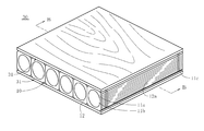
- FIG. 1 is a perspective view of a bamboo board according to a first embodiment of the present invention.
- FIG. 2 is a sectional view taken along line AA in FIG. 1.
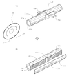
- (A) is a perspective view of the bamboo basket from which the leaf has been removed, and (b) is a perspective view of a rectangular tube-shaped element body obtained by cutting the surface layer of the bamboo basket.
- (A) is sectional drawing of the bamboo basket corresponding to Fig.3 (a)
- (b) is sectional drawing of the square cylindrical element
- A) is sectional drawing of the bamboo basket in another form,
- (b) is sectional drawing of a square cylindrical element
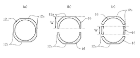
- FIG. 9 is a sectional view taken along line BB in FIG. It is a perspective view of the composite board of 3rd Embodiment of this invention. It is CC sectional view taken on the line of FIG. (A) is sectional drawing of a rectangular tube-shaped element body, (b), (c) is sectional drawing of the bone-shaped element body obtained by cutting off. It is a perspective view of the skeleton body corresponding to Drawing 12 (c).
- (A) is a perspective view of the rectangular tube-shaped element body obtained by cutting the bamboo basket surface layer
- (b) is a perspective view of the rectangular tube-shaped element body provided with a joint portion that can be fitted to the end portion. is there. It is process drawing which shows the procedure which joins the square cylindrical element
- the bamboo basket 11 (FIG. 3) constituting the bamboo board 10 (FIG. 1) of the present embodiment can be appropriately selected depending on the purpose and environment of use of the composite board 30 (FIG. 8).
- the family Gramineae it is possible to use all species whose stems become woody, such as wood (wood).
- types such as mushroom (Phyllostachys bambusoides), mushroom (Phyllostachys heterocycla), hachiku (Phyllostachys nigra), hotyliku (Phyllostachys aurea), or prickly pear (Phyllostachys heterocycla).
- the bamboo board 10 has a surface layer of a cylinder constituting the bamboo basket 11 such that the bamboo board 11 has two sets of two parallel surfaces facing each other in a cross section perpendicular to the longitudinal direction of the bamboo basket 11.
- a plurality of rectangular tube bodies 12 prepared by cutting 11a are prepared, the plurality of rectangular tube bodies 12 are arranged in parallel to each other, and the cutting surfaces 12a facing each other of the plurality of rectangular tube bodies 12 are arranged in the first direction. It is characterized in that it is made by being bonded and fixed through an adhesive 21.
- the bamboo basket 11 has a node portion 11c provided at an interval in the longitudinal direction of the bamboo basket 11.
- the 1st adhesive agent 21 although it can select suitably according to the intended purpose and environment of the bamboo board 10, it is preferable to use a safer water-system adhesive from the surface of work environment, disaster prevention, and pollution.
- the water-based adhesive include acrylic emulsion adhesives, SBR emulsion adhesives, vinyl acetate emulsion adhesives, and aqueous vinyl urethane adhesives.
- a method for manufacturing the bamboo board 10 using the bamboo basket 11 configured as described above will be described.
- a plurality of bamboos having respective diameters are prepared in advance, leaves are cut out from the bamboo and cut to a predetermined length to form bamboo baskets 11 (FIGS. 3 (a) and 4 (a)).
- the plurality of bamboo shoots 11 are dipped in an insect repellent and fungicide solution.
- the insect repellent / fungicide liquid include bifenthrin, permethrin, pyrethroid, imidazole and the like.
- the surface layer 11a of the cylinder constituting the bamboo basket 11 is cut to form the bamboo basket 11 into a square cylinder shape to obtain a rectangular cylinder body 12 (FIGS. 3 (b) and 4 (b)).
- the cutting is performed so that the cross section perpendicular to the longitudinal direction of the bamboo basket 11 has at least one set, preferably two sets, of parallel parallel surfaces.
- the remaining opposing surfaces are cut by cutting the front and back surfaces of the bamboo board obtained through the first bonding step, which will be described later. This corresponds to two parallel surfaces.
- the cross-sectional square-shaped rectangular body 12 is obtained.
- the rectangular cylindrical body 12 shown in FIG. 5B does not include a curved surface between the cutting surfaces 12a, a plurality of rectangular cylindrical bodies 12 are arranged in parallel to each other and the cutting surfaces 12a are bonded to each other. When this is done, the adhesion is enhanced compared to the rectangular tube-shaped body 12 shown in FIG.
- the cutting device 13 includes a circular saw blade S that can cut only one surface of the bamboo basket 11, for example.
- the bamboo basket 11 is fixed to a pedestal (not shown) on the cutting device 13 by fixing means 13a, 13a, the circular saw blade S is rotated, and the bamboo basket 11 is moved toward the circular saw blade S, or the circular saw blade S is moved toward the bamboo basket 11.
- the surface layer of the bamboo basket 11 is cut at a desired position, and a cutting surface 12 a is formed on the bamboo basket 11. This cutting is performed within the thickness range of the bamboo basket 11.
- the bamboo basket 11 is rotated by 180 degrees about its axis, and another surface layer of the bamboo basket 11 is cut by the same process as described above to form two parallel cutting surfaces 12a facing each other. .
- the bamboo basket 11 is subsequently rotated 90 degrees around its axis and cut in the same manner as described above.
- Reference numeral 11d in FIG. 4B, FIG. 5B, and FIG. 6B indicates the waste material removed by cutting.
- the cutting device 13 provided with the circular saw blade S has been described as an example. However, if the device can perform cutting capable of forming the rectangular tube-shaped element body 12, in particular, The form does not matter.
- the waste material 11d can be used as a surface material having a bamboo pattern on its surface by polishing its cutting surface with a polishing device to be described later to smooth the cutting surface and sticking it to paper or the like.
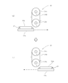
- a polishing apparatus 14 as shown in FIG. 7 is used.
- This polishing device 14 is a slide bed 14a that can reciprocate in the horizontal direction for placing the rectangular tube-shaped element body 12, and is located above the center of the reciprocation range of this slide bed 14a and is rotated by a motor (not shown).
- a tension applying mechanism (not shown) that applies a predetermined tension to the belt 14d by adjusting the distance between the belt 14d having abrasive grains bonded to the surface, the driving roller 14b, and the driven roller 14c, and this tension is applied.
- the belt 14d is moved up and down together with the driving roller 14b and the driven roller 14c, and the belt 14d is moved to the square cylindrical body 12 on the slide bed 14a.
- a lifting-pressing mechanism for pressing at a constant pressure (not shown).
- the rectangular cylindrical body 12 is fixed on the slide bed 14a of the polishing apparatus 14 (FIG. 7A), the belt 14d is rotated together with the driving roller 14b and the driven roller 14c, and the belt 14d is driven by the lifting / pressing mechanism.
- the slide bed 14a is reciprocated while being lowered together with the roller 14b and the driven roller 14c (FIGS. 7A and 7B). Thereby, one cutting surface of the rectangular tube-shaped element body 12 is polished, and the cutting surface 12a becomes smooth. Other surfaces are smoothed in the same manner as described above.
- the length of the molded rectangular tube body 12 is insufficient in the longitudinal direction and a bamboo board having a desired size cannot be manufactured, as shown in FIG. 14, at least one of the rectangular tube body 12 A joint portion 12b that can be fitted to the end portion is formed, and as shown in FIG. 15, the end portions of the rectangular cylindrical element bodies 12 that are adjacent to each other in the length direction are joined together by the joint portion 12b.
- the joining strength is raised by apply
- FIG. 16 A known general shape such as a sawtooth shape, an L shape, or a combination of a convex shape and a concave shape as shown in FIGS.
- a plurality of the cut and shaped square tube bodies 12 are prepared, and the plurality of square tube bodies 12 are arranged in parallel to each other.
- the 1st adhesive agent 21 is apply
- the 1st adhesive agent 21 should just be apply
- the mutually facing cutting surfaces 12 a of the plurality of rectangular tubular bodies 12 are bonded via the first adhesive 21. Thereby, the bamboo board 10 using the rectangular tube-shaped element body 12 is manufactured.
- the manufactured bamboo board 10 is weak in the bonding direction, but a plurality of such bamboo boards 10 are prepared, and the longitudinal directions of the rectangular cylindrical body 12 constituting the bamboo board 10 are orthogonal to each other. As described above, by laminating each bamboo board 10 via the first adhesive 21, the strength can be greatly improved. Furthermore, another bamboo board is produced using a bamboo basket having a diameter different from that of the bamboo basket 11 used in the bamboo board 10 manufactured as described above, and these bamboo boards are laminated via the first adhesive 21. Even so, the strength can be greatly improved.
- the surface layer 11a of the plurality of bamboo baskets 11 is removed by a cutting device to be formed into a rectangular tube shape to form a rectangular tube body 12, and the cutting surfaces 12a facing each other are formed. Since it adhere
- the composite board 30 of this embodiment includes the bamboo board 10 of the first embodiment and a face material 31 laminated on one or both surfaces of the bamboo board 10 with a second adhesive 32.
- a face material 31 a plywood, a particle board, a medium fiber board, a single board, or paper is mentioned.
- the second adhesive 32 can be appropriately selected depending on the purpose of use of the composite board 30 and the environment, but an aqueous adhesive is preferably used.
- the configuration other than the above is the same as that of the first embodiment.
- a method for manufacturing the composite board 30 configured as described above will be described. After the second adhesive 32 is applied to one or both surfaces of the bamboo board 10, the face material 31, the second adhesive 32 is applied to the application surface of the bamboo board 10 to which the second adhesive 32 is applied. 31 is adhered. Thereby, the composite board 30 is manufactured. In addition, when the bamboo board 10 and the face materials 31 and 31 are bonded via the second adhesive 32, pressure is applied to the bamboo board 10 and the face materials 31 and 31 so that the bonded surfaces are in close contact with each other. Is preferred.
- the composite board 30 manufactured in this way when one surface or both surfaces of the bamboo board 10 and the face material 31 are bonded together by the second adhesive 32, the front and back surfaces of the bamboo board 10 are cut surfaces 12a.
- the bamboo board formed without cutting the surface layers constituting the front and back surfaces and the face material 31 can be bonded more easily and strongly.
- 10 to 13 show a third embodiment of the present invention.
- 10 to 13 the same reference numerals as those in FIGS. 3 to 5, 8, and 9 denote the same components.
- two opposing surfaces are cut off in the longitudinal direction of the rectangular tube-shaped body 12 to form a bone-like bone-shaped element.
- a plurality of bodies 16 are prepared, the plurality of bone-like bodies 16 are arranged in parallel to each other, and the opposed cutting surfaces 12 a that remain without being cut off of the plurality of bone-like bodies 16 are interposed via the first adhesive 21.
- the bamboo board 10 is manufactured by bonding and fixing. The configuration is the same as that of the second embodiment except that the bamboo board 10 manufactured in this way is used.
- a method for manufacturing the composite board 30 configured as described above will be described.
- a cutting and forming step is performed to obtain a rectangular tubular body 12 as shown in FIG.
- two opposite surfaces of the four surfaces of the rectangular tube-shaped element 12 are cut off in the longitudinal direction of the rectangular tube-shaped element 12 to obtain a bone-shaped bone-shaped element 16.
- the thickness W of the skeleton 16 is appropriately adjusted according to the thickness desired for the composite board 30.
- two bone elements are obtained by one cut-off, but three or more bone elements are obtained by two or more cut-offs as shown in FIG. 12 (c). Also good.
- FIG. 12 (b) two bone elements are obtained by one cut-off, but three or more bone elements are obtained by two or more cut-offs as shown in FIG. 12 (c). Also good.
- FIG. 12 (b) two bone elements are obtained by one cut-off, but three or more bone elements are obtained by two or more cut-offs as shown in FIG. 12 (c). Also good.
- FIG. 12 (b) two
- the facing surface layers 11a and 11a of the cut bone-shaped element 16 are not separated because they are joined by at least the node 11c.
- a plurality of cut-off bone bodies 16 are prepared, and the plurality of bone-like bodies 16 are arranged in parallel to each other.
- the 1st adhesive agent 21 is apply
- the 1st adhesive agent 21 should just be apply
- the opposing cutting surfaces 12 a of the plurality of bone-like bodies 16 are bonded to each other via the first adhesive 21. Thereby, the bamboo board 10 using the skeleton 16 is manufactured.
- the manufactured bamboo board 10 is weak in the bonding direction.
- a plurality of such bamboo boards 10 are prepared, and the longitudinal directions of the skeleton 16 constituting the bamboo board 10 are orthogonal to each other.
- the strength can be greatly improved.
- another bamboo board is produced using a bamboo basket having a diameter different from that of the bamboo basket 11 used in the bamboo board 10 manufactured as described above, and these bamboo boards are laminated via the first adhesive 21. Even so, the strength can be greatly improved.
- the bamboo board 10 using the manufactured bone-like element 16 and the bamboo board using the rectangular tube-like element 12 obtained in the first embodiment are connected via the first adhesive 21. You may laminate. Except for manufacturing the composite board 30 using the bamboo board 10 using the bone-like element 16, the description is omitted because it is substantially the same as the second embodiment.
- the composite board 30 manufactured in this way uses the bone-like body 16 obtained by cutting to an arbitrary thickness in the cutting-off process. Since the thickness can be adjusted, for example, a thin composite board can be manufactured even if the bamboo basket 11 used has a large diameter. Since operations and effects other than those described above are substantially the same as those of the second embodiment, repeated description will be omitted.
- the surface layer of a plurality of bamboo baskets is removed with a cutting device and formed into a rectangular tube shape to form a rectangular tube body, and the opposing cutting surfaces are bonded together with a first adhesive. It can be bonded more easily and strongly than the case where the surface layers of each bamboo basket without being cut are bonded.
- bamboo bamboo boards are produced in a cylindrical shape without splitting the bamboo basket and cutting from the arc-shaped bamboo material into a flat plate shape, so this occurs when using a bamboo material molded into a flat plate shape. There is little distortion such as warping.
- the bamboo board is manufactured using the original hollow structure of the bamboo, a hollow portion is provided therein, so that a lightweight bamboo board can be obtained as compared with the solid structure.
Landscapes
- Engineering & Computer Science (AREA)
- Life Sciences & Earth Sciences (AREA)
- Forests & Forestry (AREA)
- Wood Science & Technology (AREA)
- Mechanical Engineering (AREA)
- Manufacturing & Machinery (AREA)
- Ceramic Engineering (AREA)
Abstract
Description
本実施の形態の竹製ボード10(図1)を構成する竹桿11(図3)としては、複合ボード30(図8)の使用目的や環境によって適宜選択し得るものであるが、イネ目イネ科タケ亜科のうち、木本(木)のように茎が木質化する種の全てを使用可能である。例えば、マダケ(Phyllostachys bambusoides)、モウソウチク(Phyllostachys heterocycla)、ハチク(Phyllostachys nigra)、ホテイチク(Phyllostachys aurea)又はキッコウチク(Phyllostachys heterocycla)等の種類を用いることが好ましい。
成形された角筒状素体12の長手方向の長さが足りず、所望の大きさの竹製ボードを製造できない場合は、図14に示すように、角筒状素体12の少なくとも一方の端部に勘合可能な継手部12bを形成し、図15に示すように、互いに長さ方向に隣り合う角筒状素体12の端部同士を継手部12bで継ぎ合わせて長尺の角筒状素体12とすることで、所望の大きさの竹製ボードを製造することができる。また、図示しないが、継手部12bの継ぎ合わせ面には接着剤を塗布することで、その接合強度を高める。
なお、図14及び図15では継手部12bとして、フィンガージョイント加工が施された複数の凹凸を有する形状としたが、端部同士が勘合可能であれば形状は特に限定されず、例えば、図16(a)~図16(c)に示すような、鋸歯状やL字形状、凸状と凹状の組み合わせなど公知の一般的な形状を採用することができる。
図8,図9は本発明の第2の実施の形態を示す。図8,図9において図1,図2と同一符号は同一部品を示す。この実施の形態の複合ボード30は、第1の実施の形態の竹製ボード10と、この竹製ボード10の片面又は両面に第2接着剤32を介して積層された面材31とを備える。面材31としては、合板、パーティクルボード、中質繊維板、単板又は紙が挙げられる。また第2接着剤32としては、複合ボード30の使用目的や環境によって適宜選択し得るものであるが、水系接着剤を用いることが好ましい。上記以外は第1の実施の形態と同一に構成される。
図10~図13は本発明の第3の実施の形態を示す。図10~図13において図3~図5,図8,図9と同一符号は同一部品を示す。この実施の形態では、切削成形工程で得られた角筒状素体12の四面のうち、相対向する二面が角筒状素体12の長手方向に切り落とされてなる骨状の骨状素体16を複数用意し、この複数の骨状素体16を互いに平行に配列し、複数の骨状素体16の切り落とされずに残存する相対向する切削面12a同士を第1接着剤21を介して接着固定して竹製ボード10を製造する。このように製造された竹製ボード10を用いる以外は第2の実施の形態と同一に構成される。
11 竹桿
12 角筒状素体
16 骨状素体
21 第1接着剤
30 複合ボード
31 面材
32 第2接着剤
また、従来のように、竹桿を割裂し、弧状の竹材から平板状に切削成形することなく、筒状のまま竹製ボードを製造するので、平板状に成形した竹材を使用する際に生じていた反り等の歪みを生じることが少ない。
また、竹本来の中空構造を利用して竹製ボードを製造するので、その内部に空洞部が備えられるため、中実構造に比べて軽量の竹製ボードが得られる。
Claims (12)
- 竹桿(11)の長手方向に直交する断面が相対向する平行な二面を二組有するように、前記竹桿(11)を構成する筒の表層(11a)を切削してなる角筒状素体(12)を複数用意し、前記複数の角筒状素体(12)を互いに平行に配列し、前記複数の角筒状素体(12)の相対向する切削面(12a)同士を第1接着剤(21)を介して接着固定して作られたことを特徴とする竹製ボード。
- 請求項1記載の角筒状素体(12)の四面のうち、相対向する二面が前記角筒状素体(12)の長手方向に切り落とされてなる骨状素体(16)を複数用意し、前記複数の骨状素体(16)を互いに平行に配列し、前記複数の骨状素体(16)の切り落とされずに残存する相対向する切削面(12a)同士を第1接着剤(21)を介して接着固定して作られたことを特徴とする竹製ボード。
- 前記第1接着剤(21)が水系接着剤である請求項1又は2記載の竹製ボード。
- 請求項1ないし3いずれか1項に記載の竹製ボード(10)と、前記竹製ボード(10)の片面又は両面に第2接着剤(32)を介して積層された面材(31)とを備えた複合ボード。
- 前記第2接着剤(32)が水系接着剤である請求項4記載の複合ボード。
- 前記面材(31)が合板、パーティクルボード、中質繊維板、単板又は紙の基材からなる請求項4記載の複合ボード。
- 竹桿(11)の長手方向に直交する断面が相対向する平行な二面を少なくとも一組有するように、前記竹桿(11)を構成する筒の表層(11a)を切削して前記竹桿(11)を角筒状に成形して角筒状素体(12)を得る切削成形工程と、
前記角筒状素体(12)を複数用意して前記複数の角筒状素体(12)を互いに平行に配列し、前記複数の角筒状素体(12)の相対向する切削面(12a)に第1接着剤(21)を塗布する第1接着剤塗布工程と、
前記第1接着剤(21)を介して前記複数の角筒状素体(12)の相対向する切削面(12a)同士を接着する第1接着工程と
を含むことを特徴とする竹製ボードの製造方法。 - 竹桿(11)の長手方向に直交する断面が相対向する平行な二面を少なくとも一組有するように、前記竹桿(11)を構成する筒の表層(11a)を切削して前記竹桿(11)を角筒状に成形して角筒状素体(12)を得る切削成形工程と、
前記角筒状素体(12)の四面のうち相対向する二面を前記角筒状素体(12)の長手方向に切り落として骨状の骨状素体(16)を得る切り落とし工程と、
前記骨状素体(16)を複数用意して前記複数の骨状素体(16)を互いに平行に配列し、前記複数の骨状素体(16)の切り落とされていない相対向する切削面(12a)に第1接着剤(21)を塗布する第1接着剤塗布工程と、
前記第1接着剤(21)を介して前記複数の骨状素体(16)の相対向する切削面(12a)同士を接着する第1接着工程と
を含むことを特徴とする竹製ボードの製造方法。 - 前記第1接着剤(21)が水系接着剤である請求項7又は8記載の竹製ボードの製造方法。
- 請求項7ないし9いずれか1項に記載の方法で製造された竹製ボード(10)の片面又は両面に第2接着剤(32)を塗布する第2接着剤塗布工程と、
前記第2接着剤(32)が塗布された竹製ボード(10)の塗布面に前記第2接着剤(32)を介して面材(31)を接着する第2接着工程と
を含む複合ボードの製造方法。 - 前記第2接着剤(32)が水系接着剤である請求項10記載の複合ボードの製造方法。
- 前記面材(31)が合板、パーティクルボード、中質繊維板、単板又は紙の基材からなる請求項10記載の複合ボードの製造方法。
Priority Applications (5)
| Application Number | Priority Date | Filing Date | Title |
|---|---|---|---|
| DE11859890.3T DE11859890T1 (de) | 2011-02-28 | 2011-07-28 | Bambusplatte und Verbundplatte sowie Herstellungsverfahren dafür |
| US13/984,150 US20130316127A1 (en) | 2011-02-28 | 2011-07-28 | Bamboo board and a composite board and fabrication method for same |
| EP11859890.3A EP2682242A4 (en) | 2011-02-28 | 2011-07-28 | A bamboo board and a composite board and fabrication method for same |
| CN2011800586506A CN103249532A (zh) | 2011-02-28 | 2011-07-28 | 竹制板、复合板及其制造方法 |
| JP2013502132A JP5364216B2 (ja) | 2011-02-28 | 2011-07-28 | 竹製ボード及び複合ボード並びにそれらの製造方法 |
Applications Claiming Priority (2)
| Application Number | Priority Date | Filing Date | Title |
|---|---|---|---|
| JP2011041753 | 2011-02-28 | ||
| JP2011-041753 | 2011-02-28 |
Publications (1)
| Publication Number | Publication Date |
|---|---|
| WO2012117581A1 true WO2012117581A1 (ja) | 2012-09-07 |
Family
ID=46757535
Family Applications (1)
| Application Number | Title | Priority Date | Filing Date |
|---|---|---|---|
| PCT/JP2011/067206 Ceased WO2012117581A1 (ja) | 2011-02-28 | 2011-07-28 | 竹製ボード及び複合ボード並びにそれらの製造方法 |
Country Status (6)
| Country | Link |
|---|---|
| US (1) | US20130316127A1 (ja) |
| EP (1) | EP2682242A4 (ja) |
| JP (1) | JP5364216B2 (ja) |
| CN (1) | CN103249532A (ja) |
| DE (1) | DE11859890T1 (ja) |
| WO (1) | WO2012117581A1 (ja) |
Families Citing this family (13)
| Publication number | Priority date | Publication date | Assignee | Title |
|---|---|---|---|---|
| ES2574356B1 (es) * | 2014-12-16 | 2017-05-05 | Manuel PÉREZ ROMERO | Unión estructural dentada a testero para tablas planas, y método de contrucción |
| WO2016110770A1 (en) * | 2015-01-08 | 2016-07-14 | Ake Gustafson | Sheet made of used brik packages |
| DE202015104295U1 (de) | 2015-08-14 | 2015-10-05 | Jörn Niederländer | Stabelement |
| CN105150297A (zh) * | 2015-09-25 | 2015-12-16 | 广西贺州市灵峰木业科技有限公司 | 一种新型木质板材及其加工方法 |
| CN105171855B (zh) * | 2015-09-25 | 2017-12-22 | 广西贺州市灵峰木业科技有限公司 | 一种新型实木板材及其加工方法 |
| US10940665B2 (en) * | 2016-04-13 | 2021-03-09 | City University Of Hong Kong | Structural panel, a structural system and a method of forming a structural panel |
| BR112018073225A2 (pt) * | 2016-05-12 | 2019-02-19 | Air Bamboo Ind Gmbh | componente com placas de cobertura e segmentos tubulares de madeira |
| US11084245B2 (en) * | 2019-01-09 | 2021-08-10 | Six Minutes LLC | Cross-laminated timber having a conduit therein |
| CN110625706A (zh) * | 2019-10-18 | 2019-12-31 | 湖南中集竹木业发展有限公司 | 一种集装箱底板和制作方法 |
| EP4188659A4 (en) | 2020-07-31 | 2024-07-17 | Global Bamboo Technologies Inc. | BAMBOO HYBRID STRUCTURAL PANELS AND STRUCTURAL SECTIONS |
| CN112792940B (zh) * | 2021-02-05 | 2024-05-24 | 西南林业大学 | 一种离散型全竹交叉层积材及其制造方法 |
| US20230364886A1 (en) * | 2022-05-12 | 2023-11-16 | Virginia Tech Intellectual Properties, Inc. | Lightly modified bamboo composite systems |
| CN117325264A (zh) * | 2023-11-10 | 2024-01-02 | 龙泉市金茂五金有限公司 | 弧形基片竹胶棍胶合工艺及生产装置 |
Citations (7)
| Publication number | Priority date | Publication date | Assignee | Title |
|---|---|---|---|---|
| JPS5777342U (ja) * | 1980-10-22 | 1982-05-13 | ||
| JPS58150046U (ja) * | 1982-03-31 | 1983-10-07 | 銘建工業株式会社 | 間伐材利用の造船足場板 |
| JPS6265205U (ja) * | 1985-10-14 | 1987-04-23 | ||
| JPS6394704U (ja) * | 1986-12-10 | 1988-06-18 | ||
| JPH0924505A (ja) | 1995-07-10 | 1997-01-28 | Mitsuba:Kk | 竹集成材 |
| JPH10166312A (ja) | 1996-12-13 | 1998-06-23 | Ishii Takuji | 竹材を集成材に加工する方法 |
| JP2002036211A (ja) * | 2000-07-25 | 2002-02-05 | Ishida Engineering Kk | 竹材をコアとしたパネル材 |
Family Cites Families (9)
| Publication number | Priority date | Publication date | Assignee | Title |
|---|---|---|---|---|
| GB916466A (en) * | 1960-02-09 | 1963-01-23 | Howard Francis Root | Hexaformed bamboo honeycomb panel structure |
| JP2001277209A (ja) * | 2000-04-03 | 2001-10-09 | Teori:Kk | 竹集成体製品並びに竹集成体製品の製造法 |
| CN2491538Y (zh) * | 2000-12-21 | 2002-05-15 | 王金山 | 竹制方管粘合板 |
| US6596362B1 (en) * | 2002-01-29 | 2003-07-22 | Min-Ju Chung | Wooden stairtread |
| DE20310246U1 (de) * | 2003-07-03 | 2004-11-04 | Schwabe, Thorsten, Dipl.-Ing. | Bambuskernkonstruktion, für Snowboard und Ski aller Art, bestehend aus einem innenliegenden, von Laminaten unabhängigen, in sich biege- und verwindungssteifen Torsionskasten aus Bambus |
| CN101323124B (zh) * | 2007-12-07 | 2010-08-11 | 国家林业局北京林业机械研究所 | 竹材原态多方重组材料及其制造方法 |
| CN201198158Y (zh) * | 2007-12-26 | 2009-02-25 | 国家林业局北京林业机械研究所 | 竹材原态多方重组材料 |
| US20110151172A1 (en) * | 2008-08-22 | 2011-06-23 | Wansi Fu | Prestress structural material formed by reorganization with polygonal original bamboo and the manufacturing method |
| CN101885199B (zh) * | 2009-05-14 | 2014-07-02 | 国家林业局北京林业机械研究所 | 竹材原态多方重组预应力结构材料的制造方法 |
-
2011
- 2011-07-28 JP JP2013502132A patent/JP5364216B2/ja active Active
- 2011-07-28 EP EP11859890.3A patent/EP2682242A4/en not_active Withdrawn
- 2011-07-28 WO PCT/JP2011/067206 patent/WO2012117581A1/ja not_active Ceased
- 2011-07-28 CN CN2011800586506A patent/CN103249532A/zh active Pending
- 2011-07-28 DE DE11859890.3T patent/DE11859890T1/de active Pending
- 2011-07-28 US US13/984,150 patent/US20130316127A1/en not_active Abandoned
Patent Citations (7)
| Publication number | Priority date | Publication date | Assignee | Title |
|---|---|---|---|---|
| JPS5777342U (ja) * | 1980-10-22 | 1982-05-13 | ||
| JPS58150046U (ja) * | 1982-03-31 | 1983-10-07 | 銘建工業株式会社 | 間伐材利用の造船足場板 |
| JPS6265205U (ja) * | 1985-10-14 | 1987-04-23 | ||
| JPS6394704U (ja) * | 1986-12-10 | 1988-06-18 | ||
| JPH0924505A (ja) | 1995-07-10 | 1997-01-28 | Mitsuba:Kk | 竹集成材 |
| JPH10166312A (ja) | 1996-12-13 | 1998-06-23 | Ishii Takuji | 竹材を集成材に加工する方法 |
| JP2002036211A (ja) * | 2000-07-25 | 2002-02-05 | Ishida Engineering Kk | 竹材をコアとしたパネル材 |
Non-Patent Citations (1)
| Title |
|---|
| See also references of EP2682242A4 |
Also Published As
| Publication number | Publication date |
|---|---|
| EP2682242A4 (en) | 2017-08-23 |
| US20130316127A1 (en) | 2013-11-28 |
| DE11859890T1 (de) | 2014-03-13 |
| JPWO2012117581A1 (ja) | 2014-07-07 |
| CN103249532A (zh) | 2013-08-14 |
| EP2682242A1 (en) | 2014-01-08 |
| JP5364216B2 (ja) | 2013-12-11 |
Similar Documents
| Publication | Publication Date | Title |
|---|---|---|
| JP5364216B2 (ja) | 竹製ボード及び複合ボード並びにそれらの製造方法 | |
| KR101147274B1 (ko) | 가구용 패널의 제조방법 | |
| RU2659238C2 (ru) | Внутренний слой для многослойного композита, имеющий деревянные элементы | |
| JP6336964B2 (ja) | ジグザグ状木材要素を含むコア層及びコア層を含む多層複合材 | |
| KR20190033663A (ko) | 허니콤 코어 구조물 | |
| US11208806B2 (en) | Lightweight construction board containing wave-like elements | |
| JP2000015610A (ja) | 床材および敷物 | |
| JPH0957714A (ja) | 竹材を用いた構造用集成材及びその製造方法 | |
| EP1616679A1 (en) | Oblique veneer laminated material and method of manufacturing the same | |
| JP2000263520A (ja) | 造作部材 | |
| CN111331869A (zh) | 一种无封边蜂窝板的封边工艺 | |
| US10668699B2 (en) | Multilayer composite having corrugated wooden elements | |
| CN1037299A (zh) | 高粱秆层压板及其制作方法 | |
| CN110614681A (zh) | 一种采用竹集成材与规格材制备复合交错层积材的方法 | |
| JP2000153508A (ja) | 複合集成材 | |
| CN103963118A (zh) | 一种实木薄板及其拼板工艺 | |
| SE536128C2 (sv) | Förfarande för tillverkning av skivformat sandwichmaterial med wellpappkärna och ytskikt av härdad spånmatta | |
| CN210589752U (zh) | 竹型材的结构 | |
| JP4093100B2 (ja) | 床材及び床材の製造方法 | |
| JP4699627B2 (ja) | 集成材の製造方法及びこの製造方法により形成された集成材 | |
| JP4328346B2 (ja) | 組子シート及びその製作方法 | |
| JP2009293364A (ja) | 化粧板 | |
| JP3338030B2 (ja) | 木質系構造材料の製造方法 | |
| CN116277365A (zh) | 一种木质家具三维立体部件的切片堆叠制造方法 | |
| JP2017087515A (ja) | 集成材、集成材の製造方法、および家具 |
Legal Events
| Date | Code | Title | Description |
|---|---|---|---|
| 121 | Ep: the epo has been informed by wipo that ep was designated in this application |
Ref document number: 11859890 Country of ref document: EP Kind code of ref document: A1 |
|
| ENP | Entry into the national phase |
Ref document number: 2013502132 Country of ref document: JP Kind code of ref document: A |
|
| WWE | Wipo information: entry into national phase |
Ref document number: 2011859890 Country of ref document: EP |
|
| WWE | Wipo information: entry into national phase |
Ref document number: 13984150 Country of ref document: US |
|
| NENP | Non-entry into the national phase |
Ref country code: DE |