WO2012117583A1 - カラー撮像装置 - Google Patents
カラー撮像装置 Download PDFInfo
- Publication number
- WO2012117583A1 WO2012117583A1 PCT/JP2011/067419 JP2011067419W WO2012117583A1 WO 2012117583 A1 WO2012117583 A1 WO 2012117583A1 JP 2011067419 W JP2011067419 W JP 2011067419W WO 2012117583 A1 WO2012117583 A1 WO 2012117583A1
- Authority
- WO
- WIPO (PCT)
- Prior art keywords
- color
- filter
- pixel
- weighted average
- pixels
- Prior art date
- Legal status (The legal status is an assumption and is not a legal conclusion. Google has not performed a legal analysis and makes no representation as to the accuracy of the status listed.)
- Ceased
Links
Images





Classifications
-
- G—PHYSICS
- G02—OPTICS
- G02F—OPTICAL DEVICES OR ARRANGEMENTS FOR THE CONTROL OF LIGHT BY MODIFICATION OF THE OPTICAL PROPERTIES OF THE MEDIA OF THE ELEMENTS INVOLVED THEREIN; NON-LINEAR OPTICS; FREQUENCY-CHANGING OF LIGHT; OPTICAL LOGIC ELEMENTS; OPTICAL ANALOGUE/DIGITAL CONVERTERS
- G02F1/00—Devices or arrangements for the control of the intensity, colour, phase, polarisation or direction of light arriving from an independent light source, e.g. switching, gating or modulating; Non-linear optics
- G02F1/01—Devices or arrangements for the control of the intensity, colour, phase, polarisation or direction of light arriving from an independent light source, e.g. switching, gating or modulating; Non-linear optics for the control of the intensity, phase, polarisation or colour
- G02F1/13—Devices or arrangements for the control of the intensity, colour, phase, polarisation or direction of light arriving from an independent light source, e.g. switching, gating or modulating; Non-linear optics for the control of the intensity, phase, polarisation or colour based on liquid crystals, e.g. single liquid crystal display cells
- G02F1/133—Constructional arrangements; Operation of liquid crystal cells; Circuit arrangements
- G02F1/1333—Constructional arrangements; Manufacturing methods
- G02F1/1335—Structural association of cells with optical devices, e.g. polarisers or reflectors
- G02F1/133509—Filters, e.g. light shielding masks
- G02F1/133514—Colour filters
-
- H—ELECTRICITY
- H04—ELECTRIC COMMUNICATION TECHNIQUE
- H04N—PICTORIAL COMMUNICATION, e.g. TELEVISION
- H04N23/00—Cameras or camera modules comprising electronic image sensors; Control thereof
- H04N23/80—Camera processing pipelines; Components thereof
- H04N23/84—Camera processing pipelines; Components thereof for processing colour signals
- H04N23/88—Camera processing pipelines; Components thereof for processing colour signals for colour balance, e.g. white-balance circuits or colour temperature control
-
- G—PHYSICS
- G06—COMPUTING OR CALCULATING; COUNTING
- G06T—IMAGE DATA PROCESSING OR GENERATION, IN GENERAL
- G06T3/00—Geometric image transformations in the plane of the image
- G06T3/40—Scaling of whole images or parts thereof, e.g. expanding or contracting
- G06T3/4015—Image demosaicing, e.g. colour filter arrays [CFA] or Bayer patterns
-
- H—ELECTRICITY
- H04—ELECTRIC COMMUNICATION TECHNIQUE
- H04N—PICTORIAL COMMUNICATION, e.g. TELEVISION
- H04N23/00—Cameras or camera modules comprising electronic image sensors; Control thereof
- H04N23/80—Camera processing pipelines; Components thereof
- H04N23/84—Camera processing pipelines; Components thereof for processing colour signals
- H04N23/843—Demosaicing, e.g. interpolating colour pixel values
-
- H—ELECTRICITY
- H04—ELECTRIC COMMUNICATION TECHNIQUE
- H04N—PICTORIAL COMMUNICATION, e.g. TELEVISION
- H04N25/00—Circuitry of solid-state image sensors [SSIS]; Control thereof
- H04N25/10—Circuitry of solid-state image sensors [SSIS]; Control thereof for transforming different wavelengths into image signals
- H04N25/11—Arrangement of colour filter arrays [CFA]; Filter mosaics
- H04N25/13—Arrangement of colour filter arrays [CFA]; Filter mosaics characterised by the spectral characteristics of the filter elements
- H04N25/134—Arrangement of colour filter arrays [CFA]; Filter mosaics characterised by the spectral characteristics of the filter elements based on three different wavelength filter elements
Definitions
- the present invention relates to a color imaging apparatus, and more particularly to a color imaging apparatus capable of suppressing the occurrence of color moire.
- FIG. 10A when a black and white vertical stripe pattern (high-frequency image) as shown in FIG. 10A is incident on an image sensor having the Bayer arrangement shown in FIG. 10B, the color is assigned to the Bayer color arrangement.
- R is a light flat
- B is a dark flat
- G is a light and shaded mosaic image, which is originally a monochrome image, Although there is no density difference (level difference) between RGB, depending on the color arrangement and the input frequency, a color is added.
- an optical low-pass filter made of a birefringent material such as crystal is disposed in front of the color image pickup device, and this is avoided by optically dropping a high frequency.
- coloring due to folding of the high-frequency signal can be reduced, but there is a problem that the resolution is lowered due to its adverse effect.
- the color filter arrangement of the color image sensor is determined based on an arrangement restriction condition in which any target pixel is adjacent in any one of three colors including the color of the target pixel and four sides of the target pixel.
- Patent Document 1 A color image sensor having a three-color random array that satisfies the above has been proposed.
- Patent Document 2 an image sensor having a color filter array alternately arranged at the second predetermined period in the other diagonal direction has been proposed (Patent Document 2).
- an image pickup apparatus includes a color image pickup device in which R and B of the three primary colors of RGB are arranged every three pixels in the horizontal and vertical directions, and G is arranged between these R and B.
- Patent Document 3 The color image pickup device described in Patent Document 3 is arranged so that the G pixel that contributes most to obtain the luminance signal is much more than the RB pixel because the resolution of the color difference signal may be lower than the luminance signal. Thus, the horizontal and vertical resolutions can be increased.
- Patent Document 1 The three-color random arrangement described in Patent Document 1 is effective for low-frequency color moire, but is not effective for false colors in the high-frequency part.
- R, G, and B filters are periodically arranged in the horizontal and vertical lines of the color filter array.
- a local region having a predetermined image size is extracted around the target pixel, and the target pixel in the local region is extracted.
- the estimated value of the other color of the target pixel position is calculated.
- the invention described in Patent Document 2 requires a calculation of a statistic (covariance value) relating to a color distribution shape and a regression calculation process, and has a problem that image processing becomes complicated.
- the color image sensor described in Patent Document 3 is not effective for false colors in the high-frequency part in the horizontal or vertical direction because there are lines of only G pixels in the horizontal or vertical direction.
- the present invention has been made in view of such circumstances, and an object of the present invention is to provide a color imaging apparatus capable of suppressing the generation of false colors in a high-frequency part by simple image processing.
- an invention according to one aspect of the present invention is directed to a method in which filters of all colors are arranged in a horizontal direction and a vertical direction on a plurality of pixels including photoelectric conversion elements arranged in a horizontal direction and a vertical direction.
- a single-plate color image pickup element in which color filters of a color filter array periodically arranged in each line are arranged, an image acquisition unit for acquiring a mosaic image from the color image pickup element, and a predetermined filter coefficient
- a weighted average filter having a relationship between the color of each pixel in the local area extracted from the mosaic image corresponding to the weighted average filter and the filter coefficient in a color in each line in the horizontal and vertical directions
- a weighted average calculating unit that calculates a weighted average value for each color based on a pixel value of each pixel in a local region extracted from a zyke image, and a pixel of a target pixel for synchronization processing at the center of the weighted average filter
- a synchronization processing unit for calculating a pixel value of another color at
- a single color filter array in which all color filters are periodically arranged in the horizontal and vertical lines is provided. Since a plate-type color image sensor is used, for each color in each line in the horizontal and vertical directions as the filter coefficient for the color of each pixel in the local area extracted from the mosaic image corresponding to the weighted average filter The sum of the filter coefficients can be set to be equal.
- the filter coefficient of the weighted average filter is equal to the ratio of the sum of each color in any line in the horizontal and vertical directions. Therefore, the filter coefficient is multiplied regardless of the frequency input in the horizontal and vertical directions. The resulting color relationship does not shift, and coloring due to high-frequency folding does not occur. That is, the weighted average value for each color calculated based on the filter coefficient of the weighted average filter and the pixel value of each pixel in the local region extracted from the mosaic image corresponding to the weighted average filter is Whatever frequency is input to the local area in the horizontal and vertical directions, the correct color in the local area is indicated.
- the pixel value of the target pixel is calculated based on the color ratio or color difference of the calculated weighted average value.
- the color filter array of the color imaging element includes a first filter corresponding to the first color that contributes most to obtain a luminance signal and other than the first color. And a second filter corresponding to the second color corresponding to the second color or more, and the basic array pattern is repeatedly arranged in the horizontal direction and the vertical direction, and corresponds to the first filter. The ratio between the number of pixels of the first color and the number of pixels of each color of the second color corresponding to the second filter is made different.
- the weighted average filter has the same ratio of the sum of the filter coefficients for each color in both the horizontal and vertical lines, so that the color relationship as a result of applying the filter coefficients does not shift, and coloring due to high-frequency folding occurs. There is nothing.
- the ratio of the number of pixels of the first color corresponding to the first filter is a pixel of each color of the second color corresponding to the second filter. It is preferably larger than the ratio of the numbers. That is, since the ratio of the number of pixels of the first color that contributes most to obtain the luminance signal is made larger than the ratio of the number of pixels of each color of the second color corresponding to the second filter, Singing can be suppressed and high frequency reproducibility is also good.
- the weighted average filter is a filter that is weighted so that a filter coefficient at the center is increased.
- the weighted average filter has filter coefficients that are left-right symmetric, up-down symmetric, and point symmetric. Therefore, when extracting a local area
- the color filter includes an R filter, a G filter, and a B filter corresponding to red (R), green (G), and blue (B) colors.
- the ratio of the weighted average value (Rf, Gf, Bf) for each color in the local region indicates the RGB ratio (color ratio) of the original color at the pixel position of the target pixel in the local region.
- the color filter includes an R filter, a G filter, and a B filter corresponding to red (R), green (G), and blue (B) colors.
- the difference in the weighted average value (Rf, Gf, Bf) for each color in the local area indicates the RGB difference (color difference) of the original color at the pixel position of the target pixel in the local area.
- the color filter includes an R filter, a G filter, and a B filter corresponding to red (R), green (G), and blue (B) colors.
- the filter array is a first array corresponding to 3 ⁇ 3 pixels, and a G filter is arranged at the center and four corners, and a B filter is arranged above and below the center G filter.
- a second array corresponding to 3 ⁇ 3 pixels, with G filters arranged at the center and four corners, with the center G filter interposed therebetween.
- the control unit has The weighted average the filter first sequence or the second sequence so that the order weighted average repeating the calculation unit and the synchronization unit is operated while sequentially moved so that the center.
- the first array and the second array both have color filters that are symmetrical vertically and horizontally, and the first array and the second array are simply replaced by an R filter and a B filter. It is. Therefore, when processing while moving the weighted average filter every 3 ⁇ 3 pixels, the total sum of the filter coefficients for each color in each line in the horizontal and vertical directions can be obtained without changing the filter coefficient of the weighted average filter.
- the ratio can be made equal.
- the filter coefficient for the color of each pixel in the local region extracted from the mosaic image corresponding to the weighted average filter is the sum of the filter coefficients for each color in each line in the horizontal and vertical directions.
- the ratio is set to be equal, and the weighted average value for each color based on the filter coefficient of the weighted average filter and the pixel value of each pixel in the local area extracted from the mosaic image corresponding to the weighted average filter Therefore, the color ratio or color difference of the weighted average value for each color in the local area indicates the color ratio or color difference of the original color at the pixel position of the target pixel in the local area.
- the pixel value of another color can be accurately estimated by interpolating the pixel value of the target pixel based on the color ratio or color difference of the calculated weighted average value.
- FIG. 1 is a block diagram showing an embodiment of a color imaging device according to the present invention
- FIG. 2 is a diagram showing a color filter array of color filters provided in the color image sensor of the first embodiment
- FIG. 3 is a diagram showing a basic array pattern included in the color filter array of the color image sensor of the first embodiment
- FIG. 4 is a diagram showing a state in which the basic array pattern of 6 ⁇ 6 pixels included in the color filter array of the color image sensor of the first embodiment is divided into an A array and a B array of 3 ⁇ 3 pixels, and these are arranged. Is
- FIG. 5 is a diagram showing a weighted average filter applied to the color image sensor of the first embodiment
- FIG. 5 is a diagram showing a weighted average filter applied to the color image sensor of the first embodiment
- FIG. 6A is a diagram showing an image when there is a high frequency input of vertical stripes
- FIG. 6B is a diagram used to explain that color shift does not occur in the weighted average color that has been subjected to the weighted average filter when high-frequency vertical stripes are input
- FIG. 7 is a diagram showing a second embodiment of a color imaging device and a weighted average filter applied to the present invention
- FIG. 8 is a diagram showing a third embodiment of a color image sensor applied to the present invention
- FIG. 9A is a diagram showing a third embodiment of a weighted average filter applied to the color image sensor of the third embodiment
- FIG. 9B is a diagram showing a weighted average filter applied when the 6 ⁇ 6 pixel local region shown in FIG. 9A is moved by two pixels in the horizontal direction
- FIG. 10 is a diagram used for explaining a problem of a color image sensor having a color filter with a conventional Bayer array.
- FIG. 1 is a block diagram showing an embodiment of a color imaging apparatus according to the present invention.
- the subject is imaged by the photographing optical system 10, and a light image indicating the subject image is formed on the light receiving surface of the color image sensor 12 (the color image sensor of the first embodiment).
- the color image sensor 12 includes a plurality of pixels (not shown) made of photoelectric conversion elements arranged in a horizontal direction and a vertical direction (two-dimensional arrangement), and a predetermined color filter arranged on the light receiving surface of each pixel.
- This is a single-plate type color image pickup device composed of an array of color filters. Note that the color filter array of the color image pickup device 12 is such that filters of all colors of red (R), green (G), and blue (B) are periodically arranged in the horizontal and vertical lines. The details will be described later.
- the subject image formed on the color image sensor 12 is converted into a signal charge corresponding to the amount of incident light by the photoelectric conversion element.
- the signal charge accumulated in each photoelectric conversion element is sequentially read out from the color imaging element 12 as a voltage signal (image signal) corresponding to the signal charge based on a drive pulse given from the drive unit 18 according to a command from the control unit 20.
- the image signals read from the color image sensor 12 are R, G, and B signals that indicate R, G, and B mosaic images corresponding to the color filter array of the color image sensor 12.
- the color image sensor 12 is not limited to a CCD (Charge-Coupled Device) color image sensor, but may be another type of image sensor such as a CMOS (Complementary Metal Oxide Semiconductor) image sensor.
- the image signal read from the color imaging device 12 is input to the imaging processing unit 14.
- the imaging processing unit 14 includes a correlated double sampling circuit (CDS) for removing reset noise included in the image signal, an AGC circuit for amplifying the image signal and controlling it to a certain level, and an A / D A conversion unit is included, and the input image signal is subjected to correlated double sampling processing and amplified, and thereafter, the RAW data converted into a digital image signal is output to the image processing unit 16.
- CDS correlated double sampling circuit
- the image processing unit 16 includes a white balance correction circuit, a gamma correction circuit, and a synchronization processing circuit according to the present invention (all RGB colors for each pixel from an RGB mosaic image associated with the color filter array of the single-plate color image sensor 12).
- the RAW data is subjected to required signal processing to generate image data (YUV data) composed of luminance data (Y data) and color difference data (Cr, Cb data).
- the image data generated by the image processing unit 16 is subjected to compression processing conforming to the JPEG standard for still images by a compression / decompression processing circuit, and compression processing conforming to the MPEG2 standard for moving images. After that, it is recorded on a recording medium (memory card), and is output and displayed on a display means (not shown) such as a liquid crystal monitor.
- the color filter array of the color image sensor 12 has the following features (1), (2), and (3).
- FIG. 2 is a diagram showing a color filter array of color filters provided in the color image sensor 12.
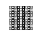
- the color filter array of the color image sensor 12 includes a basic array pattern P (pattern indicated by a thick frame) composed of a square array pattern corresponding to 6 ⁇ 6 pixels. It is repeatedly arranged in the horizontal and vertical directions. That is, in this color filter array, R, G, and B color filters (R filter, G filter, and B filter) are arrayed with a predetermined periodicity.
- the R filter, G filter, and B filter are arranged with a predetermined periodicity in this way, when performing R, G, B signal readout processing from the color image sensor 12, processing is performed according to a repetitive pattern. It can be performed.
- FIG. 3 shows a state in which the basic array pattern P shown in FIG. 2 is divided into 4 ⁇ 3 ⁇ 3 pixels.
- the basic array pattern P includes a 3 ⁇ 3 pixel A array surrounded by a solid frame and a 3 ⁇ 3 pixel B array surrounded by a broken frame as shown in FIG. It can also be understood that the array is arranged alternately in the vertical direction.
- G filters which are luminance system pixels, are arranged at the four corners and the center, and are arranged on both diagonal lines.
- the R filter is arranged in the horizontal direction with the central G filter interposed therebetween, and the B filter is arranged in the vertical direction.
- the B filter is arranged in the horizontal direction with the central G filter interposed therebetween.
- the R filters are arranged in the vertical direction. That is, in the A array and the B array, the positional relationship between the R filter and the B filter is reversed, but the other arrangements are the same.
- the basic array pattern of the color filter array shown in FIG. 2 is point-symmetric with respect to the center of the basic array pattern (the centers of the four G filters). As shown in FIG. 3, the A array and the B array in the basic array pattern are also point-symmetric with respect to the central G filter.
- the basic arrangement pattern of the color filter array shown in FIG. 2 is that the number of R, G, and B pixels corresponding to the R, G, and B filters in the basic arrangement pattern is 8 pixels, 20 pixels, and 8 pixels, respectively. It has become. That is, the ratio of the number of pixels of RGB pixels is 2: 5: 2, and the ratio of the number of G pixels that contributes most to obtain a luminance signal is the ratio of R pixels and B pixels of other colors. It is larger than the ratio of the number of pixels.
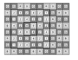
- FIG. 5 is a diagram showing an embodiment of a weighted average filter used in the synchronization processing circuit of the image processing unit 16, and particularly shows filter coefficients of the weighted average filter.
- this weighted average filter (the weighted average filter of the first embodiment) has a 9 ⁇ 9 kernel size, and the filter coefficients shown in FIG. 5 are set.
- the filter coefficient of the weighted average filter is obtained by extracting a 9 ⁇ 9 pixel local area from the mosaic image obtained from the color image sensor 12 so that the A array is in the center, and changing the color of each pixel in the local area.
- the filter coefficients are extracted for each color and the sum of the filter coefficients for each color is obtained, the ratio of the sum of the filter coefficients for each RGB color in each line in the horizontal and vertical directions is equal ( The filter coefficient is set so as to be 1: 1: 1.
- this weighted average filter has a large 3 ⁇ 3 filter coefficient in the center when comparing the filter coefficients for each region divided into 3 ⁇ 3 sizes, and then 3 ⁇ 3 on the top, bottom, left and right sides of the center.
- the filter coefficients are weighted so that the filter coefficients are large and the 3 ⁇ 3 filter coefficients at the four corners are the smallest.
- the filter coefficient is set so that this weighted average filter is left-right symmetric, up-down symmetric, and point symmetric.
- the weighted average value for each RGB is calculated based on the weighted average filter having the above configuration and the pixel value of each pixel in the 9 ⁇ 9 pixel local region extracted from the mosaic image, the color based on the weighted average value for each RGB is Regardless of the frequency input in the horizontal and vertical directions, no color shift occurs and coloring due to high-frequency folding does not occur.
- the sum of the filter coefficients of each color is 32:32:32 (see FIG. 6B), and it can be seen from the color ratio that it is black and white.
- a local area of 9 ⁇ 9 pixels is extracted from the mosaic image obtained from the color image sensor 12 so that the A array is in the center, and the pixel value of each pixel in the local area and the weight A weighted average value for each color of RGB is calculated based on the filter coefficient of the average filter. That is, the pixel value of each pixel in the local area is multiplied by the filter coefficient of the weighted average filter at each pixel position, the multiplication result is added for each color to obtain the sum for each color, and the sum for each color is further calculated.
- the weighted average value is calculated by dividing by 64. Note that 64 is the total sum of the filter coefficients for each RGB of the weighted average filter.
- a ratio (color ratio) of the RGB weighted average values is calculated from the RGB weighted average values calculated as described above.
- the central 3 ⁇ 3 pixel (the pixel in the thick frame shown in FIG. 5) in the local region of 9 ⁇ 9 pixels is the target pixel of the synchronization process, and the pixel value at the pixel position of the target pixel is Interpolation is performed based on the calculated color ratio, and pixel values of other colors at the pixel position are calculated.
- the target pixel of the synchronization process is a G pixel
- the pixel value is G
- the local region extracted from the mosaic image is determined for each 3 ⁇ 3 pixel. The same processing as above is performed while moving.
- a B array of 3 ⁇ 3 pixels is arranged at the center of the local area of 9 ⁇ 9 pixels after the movement. Will be located (see FIG. 4).
- the A array and the B array have the same G filter array, and only the positions of the R filter and the B filter are different.
- the weighted average filter has the same weight when performing the synchronization process while moving the local region. An average filter can be used.
- the filter coefficient is set so that the weighted average value for each RGB is calculated based on this weighted average filter, the frequency of the color based on the weighted average value for each RGB can be input in the horizontal and vertical directions. Even if there is, it is possible to accurately represent the color of the local region. Since the synchronization processing is performed based on the color based on the weighted average value for each RGB, it is possible to suppress the occurrence of false colors, thereby providing an optical low-pass filter for suppressing the occurrence of false colors. It is possible not to arrange it in the optical path from the incident surface to the imaging surface, or even when applying an optical low-pass filter, it is possible to apply one that has a weak function of cutting high frequency components to prevent false color generation , Resolution can be maintained.
- the pixel value at the pixel position of the target pixel is interpolated based on the color ratio of the weighted average value of RGB, and the pixel values of other colors at the pixel position are calculated.
- the pixel values of other colors may be calculated by interpolating the pixel values of the target pixel based on the color difference of the weighted average values of RGB.
- the target pixel of the synchronization process is a G pixel
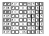
- FIG. 7 is a diagram showing a second embodiment of a color image sensor and a weighted average filter applied to the present invention, and in particular, a color filter array of color filters provided in the color image sensor and the color filter array. The filter coefficient of the weighted average filter is shown.
- a certain horizontal line is RGBRGBRGB
- the next horizontal line is GBRGBRGBR
- the next horizontal line is BRGBRGBRG. This is repeated.
- R, G, and B color filters are arrayed with a predetermined periodicity.
- filters of all colors R, G, and B are arranged in each line in the horizontal direction and the vertical direction.
- the color filter array of the color image sensor of the second embodiment has the same characteristics as the features (1) and (2) of the color filter array of the color image sensor 12 of the first embodiment.
- the weighted average filter of the second embodiment applied to the color image sensor has a kernel size of 6 ⁇ 6 as shown by a thick frame in FIG. 7, and the filter coefficient shown in FIG. Yes.
- the filter coefficient of the weighted average filter of the second embodiment is obtained by extracting a 6 ⁇ 6 pixel local area from the mosaic image obtained from the color image sensor of the second embodiment, and each pixel in the local area.
- the filter coefficients are extracted for each color corresponding to the colors and the sum of the filter coefficients for each color is obtained, the ratio of the sum of the filter coefficients for each RGB color in each line in the horizontal and vertical directions is The filter coefficients are set to be equal (1: 1: 1).
- this weighted average filter has a large 2 ⁇ 2 filter coefficient in the center when comparing the filter coefficients for each region divided into 2 ⁇ 2 sizes, and then 2 ⁇ 2 on the top, bottom, left and right sides of the center.
- the filter coefficients are weighted so that the filter coefficients are large and the 2 ⁇ 2 filter coefficients at the four corners are the smallest.
- the filter coefficient is set so that this weighted average filter is left-right symmetric, up-down symmetric, and point symmetric.
- the weighted average value for each RGB is calculated based on the weighted average filter having the above configuration and the pixel value of each pixel in the 6 ⁇ 6 pixel local area extracted from the mosaic image, the color based on the weighted average value for each RGB is Regardless of the frequency input in the horizontal and vertical directions, no color shift occurs and coloring due to high-frequency folding does not occur.
- the weighted average value for each RGB is calculated based on the pixel value of each pixel in the 6 ⁇ 6 pixel local region extracted from the mosaic image and the filter coefficient of the weighted average filter.
- the local region extracted from the mosaic image is set in the horizontal direction or the vertical direction.
- the same processing as above is performed while moving two pixels in the direction, but in this case, the same weighted average filter can be used.
- FIG. 8 is a diagram showing a third embodiment of a color image sensor applied to the present invention, and particularly shows a color filter array of color filters provided in the color image sensor.
- FIG. 9 shows filter coefficients of a weighted average filter applied to this color image sensor.
- the color filter array of the color imaging device of the third embodiment includes a basic array pattern (pattern indicated by a thick frame) including a square array pattern corresponding to 4 ⁇ 4 pixels.
- the array pattern is repeatedly arranged in the horizontal direction and the vertical direction. That is, in this color filter array, R, G, and B color filters (R filter, G filter, and B filter) are arrayed with a predetermined periodicity.
- filters of all the colors R, G, and B are arranged in each line in the horizontal direction and the vertical direction.
- the basic array pattern of the color filter array is point-symmetric with respect to the center of the basic array pattern.
- the numbers of R pixels, G pixels, and B pixels corresponding to the R, G, and B filters in the basic arrangement pattern are 4 pixels and 8 pixels, respectively. There are 4 pixels. That is, the ratio of the number of RGB pixels is 1: 2: 1, and the ratio of the number of G pixels that contributes most to obtain a luminance signal is the ratio of the R and B pixels of the other colors. It is larger than the ratio of the number of pixels.
- the color filter array of the color image sensor of the third embodiment includes the features (1), (2), (3), and (4) of the color filter array of the color image sensor 12 of the first embodiment. Has the same characteristics.
- the weighted average filter of the third embodiment applied to the color imaging device has a kernel size of 6 ⁇ 6 as shown by the thick frames in FIGS. 9A and 9B, and the filter coefficient shown in FIG. Is set.
- the filter coefficient of the weighted average filter of the third embodiment is obtained by extracting a 6 ⁇ 6 pixel local area from the mosaic image obtained from the color image sensor of the third embodiment, and each pixel in the local area.
- the filter coefficients are extracted for each color corresponding to the colors, and the sum of the filter coefficients for each color is obtained, the ratio of the sum of the filter coefficients for each RGB color in each line in the horizontal and vertical directions is The filter coefficients are set to be equal (1: 1: 1).
- this weighted average filter has a large 2 ⁇ 2 filter coefficient in the center when comparing the filter coefficients for each region divided into 2 ⁇ 2 sizes, and then 2 ⁇ 2 on the top, bottom, left and right sides of the center.
- the filter coefficients are weighted so that the filter coefficients are large and the 2 ⁇ 2 filter coefficients at the four corners are the smallest.
- the weighted average value for each RGB is calculated based on the weighted average filter having the above configuration and the pixel value of each pixel in the 6 ⁇ 6 pixel local area extracted from the mosaic image, the color based on the weighted average value for each RGB is Regardless of the frequency input in the horizontal and vertical directions, no color shift occurs and coloring due to high-frequency folding does not occur.
- the weighted average value for each RGB is calculated based on the pixel value of each pixel in the 6 ⁇ 6 pixel local region extracted from the mosaic image and the filter coefficient of the weighted average filter.
- the local area extracted from the mosaic image is set in the horizontal direction or the vertical direction.
- the same process as above is performed while moving two pixels in the direction, but in this case, a different weighted average filter is used.
- FIG. 9A when G pixels come in the upper left and lower right of 2 ⁇ 2 pixels in the center of the 6 ⁇ 6 pixel local area extracted from the mosaic image, the filter coefficients shown in FIG. 9B, the local area extracted from the mosaic image is moved to two pixels in the horizontal direction, and G pixels are located at the upper right and lower left of the 2 ⁇ 2 pixels in the center of the local area.
- a weighted average filter having a filter coefficient shown in FIG. 9B is used.
- RGB primary colors + other colors for example, emerald
- the present invention can also be applied to a color image pickup apparatus including a color image pickup element having four color filters of E)).
- the present invention provides a color image pickup including a color image pickup element having a color filter of four complementary colors, in which G is added to C (cyan), M (magenta), and Y (yellow) which are complementary colors of the primary colors RGB. It can also be applied to devices.
Landscapes
- Physics & Mathematics (AREA)
- Engineering & Computer Science (AREA)
- Signal Processing (AREA)
- Multimedia (AREA)
- Nonlinear Science (AREA)
- General Physics & Mathematics (AREA)
- Crystallography & Structural Chemistry (AREA)
- Optics & Photonics (AREA)
- Chemical & Material Sciences (AREA)
- Mathematical Physics (AREA)
- Spectroscopy & Molecular Physics (AREA)
- Theoretical Computer Science (AREA)
- Color Television Image Signal Generators (AREA)
- Image Processing (AREA)
- Optical Filters (AREA)
Abstract
Description
R=G×(Rf/Gf),B=G×(Bf/Gf)
により算出し、前記同時化処理の対象画素がR画素であり、その画素値がRの場合、前記対象画素の位置におけるG、B画素の画素値G,Bを、次式、
G=R×(Gf/Rf),B=R×(Bf/Rf)
により算出し、前記同時化処理の対象画素がB画素であり、その画素値がBの場合、前記対象画素の位置におけるG、R画素の画素値G,Rを、次式、
G=B×(Gf/Bf),R=B×(Rf/Bf)
により算出するようにしている。
R=G+(Rf-Gf),B=G+(Bf-Gf)
により算出し、前記同時化処理の対象画素がR画素であり、その画素値がRの場合、前記対象画素の位置におけるG、B画素の画素値G,Bを、次式、
G=R+(Gf-Rf),B=R+(Bf-Rf)
により算出し、前記同時化処理の対象画素がB画素であり、その画素値がBの場合、前記対象画素の位置におけるG、R画素の画素値G,Rを、次式、
G=B+(Gf-Bf),R=B+(Rf-Bf)
により算出するようにしている。
図1は本発明に係るカラー撮像装置の実施形態を示すブロック図である。
カラー撮像素子12のカラーフィルタ配列は、下記の特徴(1)、(2)及び(3)を有している。
図2はカラー撮像素子12に設けられているカラーフィルタのカラーフィルタ配列を示す図である。図2に示すように、カラー撮像素子12のカラーフィルタ配列は、6×6画素に対応する正方配列パターンからなる基本配列パターンP(太枠で示したパターン)を含み、この基本配列パターンPが水平方向及び垂直方向に繰り返し配置されている。即ち、このカラーフィルタ配列は、R、G、Bの各色のフィルタ(Rフィルタ、Gフィルタ、Bフィルタ)が所定の周期性をもって配列されている。
図2に示すカラーフィルタ配列は、R、G、Bの全ての色のフィルタが水平方向及び垂直方向の各ライン内に配置されている。
図2に示すカラーフィルタ配列の基本配列パターンは、その基本配列パターンの中心(4つのGフィルタの中心)に対して点対称になっている。また、図3に示したように、基本配列パターン内のA配列及びB配列も、それぞれ中心のGフィルタに対して点対称になっている。
図2に示すカラーフィルタ配列の基本配列パターンは、その基本配列パターン内におけるR、G、Bフィルタに対応するR画素、G画素、B画素の画素数が、それぞれ8画素、20画素、8画素になっている。即ち、RGB画素の各画素数の比率は、2:5:2になっており、輝度信号を得るために最も寄与するG画素の画素数の比率は、他の色のR画素、B画素の画素数の比率よりも大きくなっている。
図5は、画像処理部16の同時化処理回路で使用する加重平均フィルタの実施形態を示す図であり、特に加重平均フィルタのフィルタ係数に関して示している。
次に、画像処理部16の同時化処理回路によりRGBのモザイク画像を同時化処理する方法について説明する。
R=G×(Rf/Gf),B=G×(Bf/Gf) …(1)
により算出する。
G=R×(Gf/Rf),B=R×(Bf/Rf) …(2)
により算出する。
G=B×(Gf/Bf),R=B×(Rf/Bf) …(3)
により算出する。
R=G+(Rf-Gf),B=G+(Bf-Gf) …(4)
により算出する。
G=R+(Gf-Rf),B=R+(Bf-Rf) …(5)
により算出する。
G=B+(Gf-Bf),R=B+(Rf-Bf) …(6)
により算出する。
図7は本発明に適用されるカラー撮像素子及び加重平均フィルタの第2の実施形態を示す図であり、特にカラー撮像素子に設けられているカラーフィルタのカラーフィルタ配列と、これに適用される加重平均フィルタのフィルタ係数を示している。
図8は本発明に適用されるカラー撮像素子の第3の実施形態を示す図であり、特にカラー撮像素子に設けられているカラーフィルタのカラーフィルタ配列に関して示している。
上記実施形態では、RGBの3原色のカラーフィルタを有するカラー撮像素子を備えたカラー撮像装置について説明したが、本発明は、これに限らず、RGBの3原色+他の色(例えば、エメラルド(E))の4色のカラーフィルタを有するカラー撮像素子を備えたカラー撮像装置にも適用できる。
Claims (8)
- 水平方向及び垂直方向に配列された光電変換素子からなる複数の画素上に、全ての色のフィルタが水平方向及び垂直方向の各ライン内に周期的に配置されたカラーフィルタ配列のカラーフィルタが配設されてなる単板式のカラー撮像素子と、
前記カラー撮像素子からモザイク画像を取得する画像取得部と、
所定のフィルタ係数を有する加重平均フィルタであって、該加重平均フィルタに対応して前記モザイク画像から抽出される局所領域内の各画素の色と前記フィルタ係数との関係が、水平及び垂直方向の各ライン内の色毎のフィルタ係数の総和の比が等しくなるように設定された加重平均フィルタと、
前記加重平均フィルタのフィルタ係数と該加重平均フィルタに対応して前記モザイク画像から抽出される局所領域内の各画素の画素値とに基づいて色毎の加重平均値を算出する加重平均算出部と、
前記加重平均フィルタの中央部の同時化処理の対象画素の画素位置における他の色の画素値を算出する同時化処理部であって、前記対象画素の色と他の色との前記算出した加重平均値の色比又は色差に基づいて、前記対象画素の画素値を補間して前記他の色の画素値を算出する同時化処理部と、
前記加重平均フィルタに対応して前記モザイク画像から抽出する局所領域を、前記同時化処理の対象画素単位毎に移動させながら前記加重平均算出部及び同時化処理部を繰り返し動作させる制御部と、
を備えたカラー撮像装置。 - 前記カラー撮像素子のカラーフィルタ配列は、輝度信号を得るために最も寄与する第1の色に対応する第1のフィルタと前記第1の色以外の2色以上の第2の色に対応する第2のフィルタとが配列された基本配列パターンを含み、該基本配列パターンが水平方向及び垂直方向に繰り返して配置され、
前記第1のフィルタに対応する第1の色の画素数と、前記第2のフィルタに対応する第2の色の各色の画素数との比率が異なる請求項1に記載のカラー撮像装置。 - 前記第1のフィルタに対応する第1の色の画素数の比率は、前記第2のフィルタに対応する第2の色の各色の画素数の比率よりも大きい請求項2に記載のカラー撮像装置。
- 前記加重平均フィルタは、中央部のフィルタ係数が大きくなるように重み付けされているフィルタである請求項1から3のいずれか1項に記載のカラー撮像装置。
- 前記加重平均フィルタは、左右対称、上下対称及び点対称となるフィルタ係数を有する請求項1から4のいずれか1項に記載のカラー撮像装置。
- 前記カラーフィルタは、赤(R)、緑(G)、青(B)の色に対応するRフィルタ、Gフィルタ及びBフィルタが所定のカラーフィルタ配列で配置されてなり、
前記加重平均算出部により算出された前記Rフィルタ、Gフィルタ及びBフィルタに対応するR、G、B画素の画素値の色毎の加重平均値を、それぞれRf、Gf、Bfとすると、
前記同時化処理部は、
前記同時化処理の対象画素がG画素であり、その画素値がGの場合、前記対象画素の位置におけるR、B画素の画素値R,Bを、次式、
R=G×(Rf/Gf),B=G×(Bf/Gf)
により算出し、前記同時化処理の対象画素がR画素であり、その画素値がRの場合、前記対象画素の位置におけるG、B画素の画素値G,Bを、次式、
G=R×(Gf/Rf),B=R×(Bf/Rf)
により算出し、前記同時化処理の対象画素がB画素であり、その画素値がBの場合、前記対象画素の位置におけるG、R画素の画素値G,Rを、次式、
G=B×(Gf/Bf),R=B×(Rf/Bf)
により算出する請求項1から5のいずれか1項に記載のカラー撮像装置。 - 前記カラーフィルタは、赤(R)、緑(G)、青(B)の色に対応するRフィルタ、Gフィルタ及びBフィルタが所定のカラーフィルタ配列で配置されてなり、
前記加重平均算出部により算出された前記Rフィルタ、Gフィルタ及びBフィルタに対応するR、G、B画素の画素値の色毎の加重平均値を、それぞれRf、Gf、Bfとすると、
前記同時化処理部は、
前記同時化処理の対象画素がG画素であり、その画素値がGの場合、前記対象画素の位置におけるR、B画素の画素値R,Bを、次式、
R=G+(Rf-Gf),B=G+(Bf-Gf)
により算出し、前記同時化処理の対象画素がR画素であり、その画素値がRの場合、前記対象画素の位置におけるG、B画素の画素値G,Bを、次式、
G=R+(Gf-Rf),B=R+(Bf-Rf)
により算出し、前記同時化処理の対象画素がB画素であり、その画素値がBの場合、前記対象画素の位置におけるG、R画素の画素値G,Rを、次式、
G=B+(Gf-Bf),R=B+(Rf-Bf)
により算出する請求項1から5のいずれか1項に記載のカラー撮像装置。 - 前記カラーフィルタは、赤(R)、緑(G)、青(B)の色に対応するRフィルタ、Gフィルタ及びBフィルタが所定のカラーフィルタ配列で配置されてなり、
前記フィルタ配列は、3×3画素に対応する第1の配列であって、中心と4隅にGフィルタが配置され、中心のGフィルタを挟んで上下にBフィルタが配置され、左右にRフィルタが配列された第1の配列と、3×3画素に対応する第2の配列であって、中心と4隅にGフィルタが配置され、中心のGフィルタを挟んで上下にRフィルタが配置され、左右にBフィルタが配列された第2の配列とが、交互に水平方向及び垂直方向に配列されて構成され、
前記加重平均フィルタは、9×9のカーネルサイズを有し、
前記制御部は、前記加重平均フィルタを前記第1の配列又は第2の配列が中心になるように順次移動させながら前記加重平均算出部及び同時化処理部を繰り返し動作させる請求項1から7のいずれか1項に記載のカラー撮像装置。
Priority Applications (7)
| Application Number | Priority Date | Filing Date | Title |
|---|---|---|---|
| BR112012027306A BR112012027306A2 (pt) | 2011-02-28 | 2011-07-29 | aparelho de geração de imagem colorida |
| CN201180022148.XA CN102870417B (zh) | 2011-02-28 | 2011-07-29 | 彩色成像设备 |
| JP2012524426A JP5054857B1 (ja) | 2011-02-28 | 2011-07-29 | カラー撮像装置 |
| EP11859802.8A EP2683166B1 (en) | 2011-02-28 | 2011-07-29 | Color imaging device |
| RU2013138394/07A RU2551649C2 (ru) | 2011-02-28 | 2011-07-29 | Устройство формирования цветного изображения |
| US13/560,431 US8531563B2 (en) | 2011-02-28 | 2012-07-27 | Color imaging apparatus |
| US13/951,053 US8704922B2 (en) | 2011-02-28 | 2013-07-25 | Mosaic image processing method |
Applications Claiming Priority (4)
| Application Number | Priority Date | Filing Date | Title |
|---|---|---|---|
| JP2011-042514 | 2011-02-28 | ||
| JP2011042514 | 2011-02-28 | ||
| JP2011-162414 | 2011-07-25 | ||
| JP2011162414 | 2011-07-25 |
Related Child Applications (1)
| Application Number | Title | Priority Date | Filing Date |
|---|---|---|---|
| US13/560,431 Continuation US8531563B2 (en) | 2011-02-28 | 2012-07-27 | Color imaging apparatus |
Publications (1)
| Publication Number | Publication Date |
|---|---|
| WO2012117583A1 true WO2012117583A1 (ja) | 2012-09-07 |
Family
ID=46757537
Family Applications (1)
| Application Number | Title | Priority Date | Filing Date |
|---|---|---|---|
| PCT/JP2011/067419 Ceased WO2012117583A1 (ja) | 2011-02-28 | 2011-07-29 | カラー撮像装置 |
Country Status (7)
| Country | Link |
|---|---|
| US (2) | US8531563B2 (ja) |
| EP (1) | EP2683166B1 (ja) |
| JP (2) | JP5054857B1 (ja) |
| CN (2) | CN102870417B (ja) |
| BR (1) | BR112012027306A2 (ja) |
| RU (1) | RU2551649C2 (ja) |
| WO (1) | WO2012117583A1 (ja) |
Cited By (2)
| Publication number | Priority date | Publication date | Assignee | Title |
|---|---|---|---|---|
| WO2014034486A1 (ja) * | 2012-08-27 | 2014-03-06 | 富士フイルム株式会社 | 画像処理装置、方法、プログラム及び記録媒体並びに撮像装置 |
| US10783158B2 (en) | 2016-12-19 | 2020-09-22 | Datalogic IP Tech, S.r.l. | Method and algorithms for auto-identification data mining through dynamic hyperlink search analysis |
Families Citing this family (99)
| Publication number | Priority date | Publication date | Assignee | Title |
|---|---|---|---|---|
| EP1758783B1 (de) | 2004-05-25 | 2008-04-16 | VDO Automotive AG | Überwachungseinheit nebst assistenzsystem für kraftfahrzeuge |
| EP3328048B1 (en) | 2008-05-20 | 2021-04-21 | FotoNation Limited | Capturing and processing of images using monolithic camera array with heterogeneous imagers |
| US8866920B2 (en) | 2008-05-20 | 2014-10-21 | Pelican Imaging Corporation | Capturing and processing of images using monolithic camera array with heterogeneous imagers |
| US11792538B2 (en) | 2008-05-20 | 2023-10-17 | Adeia Imaging Llc | Capturing and processing of images including occlusions focused on an image sensor by a lens stack array |
| EP2502115A4 (en) | 2009-11-20 | 2013-11-06 | Pelican Imaging Corp | RECORDING AND PROCESSING IMAGES THROUGH A MONOLITHIC CAMERA ARRAY WITH HETEROGENIC IMAGE CONVERTER |
| CN103004180A (zh) | 2010-05-12 | 2013-03-27 | 派力肯影像公司 | 成像器阵列和阵列照相机的架构 |
| US8878950B2 (en) | 2010-12-14 | 2014-11-04 | Pelican Imaging Corporation | Systems and methods for synthesizing high resolution images using super-resolution processes |
| US8488031B2 (en) * | 2011-01-14 | 2013-07-16 | DigitalOptics Corporation Europe Limited | Chromatic noise reduction method and apparatus |
| EP2683166B1 (en) * | 2011-02-28 | 2017-12-13 | Fujifilm Corporation | Color imaging device |
| EP2685711B1 (en) * | 2011-03-09 | 2017-08-30 | Fujifilm Corporation | Color image pickup device |
| EP2645723B1 (en) * | 2011-03-11 | 2015-06-17 | FUJIFILM Corporation | Imaging device, method for controlling operation thereof, and imaging system |
| US8305456B1 (en) | 2011-05-11 | 2012-11-06 | Pelican Imaging Corporation | Systems and methods for transmitting and receiving array camera image data |
| US20130265459A1 (en) | 2011-06-28 | 2013-10-10 | Pelican Imaging Corporation | Optical arrangements for use with an array camera |
| WO2013043751A1 (en) | 2011-09-19 | 2013-03-28 | Pelican Imaging Corporation | Systems and methods for controlling aliasing in images captured by an array camera for use in super resolution processing using pixel apertures |
| CN104081414B (zh) | 2011-09-28 | 2017-08-01 | Fotonation开曼有限公司 | 用于编码和解码光场图像文件的系统及方法 |
| EP2763417B1 (en) | 2011-09-29 | 2019-02-27 | FUJIFILM Corporation | Device, method and program for image processing, recording medium, and imaging device |
| EP2800377A4 (en) * | 2011-12-28 | 2015-07-15 | Fujifilm Corp | IMAGING DEVICE |
| US9412206B2 (en) | 2012-02-21 | 2016-08-09 | Pelican Imaging Corporation | Systems and methods for the manipulation of captured light field image data |
| JP2013201723A (ja) * | 2012-03-26 | 2013-10-03 | Hoya Corp | 撮像素子用オンチップカラーフィルタ配列 |
| US9210392B2 (en) | 2012-05-01 | 2015-12-08 | Pelican Imaging Coporation | Camera modules patterned with pi filter groups |
| EP2873028A4 (en) | 2012-06-28 | 2016-05-25 | Pelican Imaging Corp | SYSTEMS AND METHOD FOR DETECTING DEFECTIVE CAMERA ARRAYS, OPTICAL ARRAYS AND SENSORS |
| US20140002674A1 (en) | 2012-06-30 | 2014-01-02 | Pelican Imaging Corporation | Systems and Methods for Manufacturing Camera Modules Using Active Alignment of Lens Stack Arrays and Sensors |
| US20150321644A1 (en) * | 2012-08-06 | 2015-11-12 | Conti Temic Microelectronic Gmbh | Detection of Raindrops on a Pane by Means of a Camera and Illumination |
| CN107346061B (zh) | 2012-08-21 | 2020-04-24 | 快图有限公司 | 用于使用阵列照相机捕捉的图像中的视差检测和校正的系统和方法 |
| EP2888698A4 (en) | 2012-08-23 | 2016-06-29 | Pelican Imaging Corp | PROPERTY-BASED HIGH-RESOLUTION MOTION ESTIMATION FROM LOW-RESOLUTION IMAGES RECORDED WITH AN ARRAY SOURCE |
| WO2014043641A1 (en) | 2012-09-14 | 2014-03-20 | Pelican Imaging Corporation | Systems and methods for correcting user identified artifacts in light field images |
| WO2014052974A2 (en) | 2012-09-28 | 2014-04-03 | Pelican Imaging Corporation | Generating images from light fields utilizing virtual viewpoints |
| US9143711B2 (en) | 2012-11-13 | 2015-09-22 | Pelican Imaging Corporation | Systems and methods for array camera focal plane control |
| US8830395B2 (en) * | 2012-12-19 | 2014-09-09 | Marvell World Trade Ltd. | Systems and methods for adaptive scaling of digital images |
| WO2014122804A1 (ja) * | 2013-02-05 | 2014-08-14 | 富士フイルム株式会社 | 画像処理装置、撮像装置、画像処理方法及びプログラム |
| US9462164B2 (en) | 2013-02-21 | 2016-10-04 | Pelican Imaging Corporation | Systems and methods for generating compressed light field representation data using captured light fields, array geometry, and parallax information |
| US9253380B2 (en) | 2013-02-24 | 2016-02-02 | Pelican Imaging Corporation | Thin form factor computational array cameras and modular array cameras |
| US9774789B2 (en) | 2013-03-08 | 2017-09-26 | Fotonation Cayman Limited | Systems and methods for high dynamic range imaging using array cameras |
| US8866912B2 (en) | 2013-03-10 | 2014-10-21 | Pelican Imaging Corporation | System and methods for calibration of an array camera using a single captured image |
| US9521416B1 (en) | 2013-03-11 | 2016-12-13 | Kip Peli P1 Lp | Systems and methods for image data compression |
| US9888194B2 (en) | 2013-03-13 | 2018-02-06 | Fotonation Cayman Limited | Array camera architecture implementing quantum film image sensors |
| US9519972B2 (en) | 2013-03-13 | 2016-12-13 | Kip Peli P1 Lp | Systems and methods for synthesizing images from image data captured by an array camera using restricted depth of field depth maps in which depth estimation precision varies |
| US9124831B2 (en) | 2013-03-13 | 2015-09-01 | Pelican Imaging Corporation | System and methods for calibration of an array camera |
| US9106784B2 (en) | 2013-03-13 | 2015-08-11 | Pelican Imaging Corporation | Systems and methods for controlling aliasing in images captured by an array camera for use in super-resolution processing |
| WO2014159779A1 (en) | 2013-03-14 | 2014-10-02 | Pelican Imaging Corporation | Systems and methods for reducing motion blur in images or video in ultra low light with array cameras |
| WO2014153098A1 (en) | 2013-03-14 | 2014-09-25 | Pelican Imaging Corporation | Photmetric normalization in array cameras |
| US9497429B2 (en) | 2013-03-15 | 2016-11-15 | Pelican Imaging Corporation | Extended color processing on pelican array cameras |
| US10122993B2 (en) | 2013-03-15 | 2018-11-06 | Fotonation Limited | Autofocus system for a conventional camera that uses depth information from an array camera |
| US9445003B1 (en) | 2013-03-15 | 2016-09-13 | Pelican Imaging Corporation | Systems and methods for synthesizing high resolution images using image deconvolution based on motion and depth information |
| WO2014150856A1 (en) | 2013-03-15 | 2014-09-25 | Pelican Imaging Corporation | Array camera implementing quantum dot color filters |
| US9633442B2 (en) | 2013-03-15 | 2017-04-25 | Fotonation Cayman Limited | Array cameras including an array camera module augmented with a separate camera |
| EP4604059A3 (en) | 2013-03-15 | 2025-09-17 | Adeia Imaging LLC | Systems and methods for stereo imaging with camera arrays |
| CN103218790B (zh) * | 2013-04-25 | 2016-01-27 | 华为技术有限公司 | 图像滤波的方法和滤波器 |
| US9042643B2 (en) * | 2013-06-20 | 2015-05-26 | Himax Imaging Limited | Method for demosaicking |
| US9667933B2 (en) | 2013-07-01 | 2017-05-30 | Omnivision Technologies, Inc. | Color and infrared filter array patterns to reduce color aliasing |
| US9692992B2 (en) * | 2013-07-01 | 2017-06-27 | Omnivision Technologies, Inc. | Color and infrared filter array patterns to reduce color aliasing |
| WO2015048694A2 (en) | 2013-09-27 | 2015-04-02 | Pelican Imaging Corporation | Systems and methods for depth-assisted perspective distortion correction |
| US9426343B2 (en) | 2013-11-07 | 2016-08-23 | Pelican Imaging Corporation | Array cameras incorporating independently aligned lens stacks |
| US10119808B2 (en) | 2013-11-18 | 2018-11-06 | Fotonation Limited | Systems and methods for estimating depth from projected texture using camera arrays |
| EP3075140B1 (en) | 2013-11-26 | 2018-06-13 | FotoNation Cayman Limited | Array camera configurations incorporating multiple constituent array cameras |
| US10089740B2 (en) | 2014-03-07 | 2018-10-02 | Fotonation Limited | System and methods for depth regularization and semiautomatic interactive matting using RGB-D images |
| US9247117B2 (en) | 2014-04-07 | 2016-01-26 | Pelican Imaging Corporation | Systems and methods for correcting for warpage of a sensor array in an array camera module by introducing warpage into a focal plane of a lens stack array |
| US20150363912A1 (en) * | 2014-06-12 | 2015-12-17 | Samsung Electronics Co., Ltd. | Rgbw demosaic method by combining rgb chrominance with w luminance |
| US9521319B2 (en) | 2014-06-18 | 2016-12-13 | Pelican Imaging Corporation | Array cameras and array camera modules including spectral filters disposed outside of a constituent image sensor |
| CN104296664A (zh) * | 2014-09-17 | 2015-01-21 | 宁波高新区晓圆科技有限公司 | 一种在几何尺寸视觉检测中提高检测精度的方法 |
| CN113256730B (zh) | 2014-09-29 | 2023-09-05 | 快图有限公司 | 用于阵列相机的动态校准的系统和方法 |
| KR102282457B1 (ko) * | 2014-12-05 | 2021-07-28 | 한화테크윈 주식회사 | 컬러 모아레 저감 방법, 컬러 모아레 저감 장치 및 영상 처리 장치 |
| KR102224851B1 (ko) | 2014-12-11 | 2021-03-08 | 삼성전자주식회사 | 서브 픽셀 보간을 수행하는 이미지 처리 장치 및 이미지 처리 시스템 |
| US9942474B2 (en) | 2015-04-17 | 2018-04-10 | Fotonation Cayman Limited | Systems and methods for performing high speed video capture and depth estimation using array cameras |
| US10349015B2 (en) | 2015-06-08 | 2019-07-09 | Trustees Of Dartmouth College | Image sensor color filter array pattern |
| CN104933675B (zh) * | 2015-07-02 | 2017-11-07 | 浙江大学 | 一种周期性可控的复杂镶嵌图案生成方法 |
| US10445612B2 (en) * | 2015-10-26 | 2019-10-15 | Canon Kabushiki Kaisha | Information processing apparatus, information processing method, and storage medium |
| GB2555585A (en) * | 2016-10-31 | 2018-05-09 | Nokia Technologies Oy | Multiple view colour reconstruction |
| KR102584523B1 (ko) * | 2016-11-16 | 2023-10-05 | 한화비전 주식회사 | 컬러 모아레 저감 방법 및 이를 이용한 영상 처리 장치 |
| CN107068731B (zh) * | 2017-06-09 | 2019-11-19 | 京东方科技集团股份有限公司 | 像素排列结构、显示面板、显示装置和掩模板 |
| US10482618B2 (en) | 2017-08-21 | 2019-11-19 | Fotonation Limited | Systems and methods for hybrid depth regularization |
| EP3522106A1 (en) * | 2018-01-31 | 2019-08-07 | InterDigital CE Patent Holdings | A filter array enabling easy demosaicing |
| CN110830680B (zh) * | 2018-08-08 | 2021-03-16 | 瑞昱半导体股份有限公司 | 确定滤波器系数的方法 |
| CN109357687B (zh) * | 2018-09-07 | 2022-07-08 | 上海集成电路研发中心有限公司 | 一种cmos图像传感器的缺陷检测方法 |
| CN114641863B (zh) * | 2019-05-23 | 2026-04-21 | 三星显示有限公司 | 颜色转换基板和包括该颜色转换基板的显示装置 |
| WO2021055585A1 (en) | 2019-09-17 | 2021-03-25 | Boston Polarimetrics, Inc. | Systems and methods for surface modeling using polarization cues |
| WO2021071995A1 (en) | 2019-10-07 | 2021-04-15 | Boston Polarimetrics, Inc. | Systems and methods for surface normals sensing with polarization |
| EP4066001B1 (en) | 2019-11-30 | 2026-03-04 | Intrinsic Innovation LLC | Systems and methods for transparent object segmentation using polarization cues |
| JP7462769B2 (ja) | 2020-01-29 | 2024-04-05 | イントリンジック イノベーション エルエルシー | 物体の姿勢の検出および測定システムを特徴付けるためのシステムおよび方法 |
| US11797863B2 (en) | 2020-01-30 | 2023-10-24 | Intrinsic Innovation Llc | Systems and methods for synthesizing data for training statistical models on different imaging modalities including polarized images |
| WO2021171797A1 (ja) * | 2020-02-26 | 2021-09-02 | ソニーセミコンダクタソリューションズ株式会社 | 固体撮像装置及び電子機器 |
| WO2021243088A1 (en) | 2020-05-27 | 2021-12-02 | Boston Polarimetrics, Inc. | Multi-aperture polarization optical systems using beam splitters |
| US12199351B1 (en) | 2021-01-06 | 2025-01-14 | Lockheed Martin Corporation | Phase center steering for grating lobe suppression |
| US12020455B2 (en) | 2021-03-10 | 2024-06-25 | Intrinsic Innovation Llc | Systems and methods for high dynamic range image reconstruction |
| US12069227B2 (en) | 2021-03-10 | 2024-08-20 | Intrinsic Innovation Llc | Multi-modal and multi-spectral stereo camera arrays |
| US11290658B1 (en) | 2021-04-15 | 2022-03-29 | Boston Polarimetrics, Inc. | Systems and methods for camera exposure control |
| US11954886B2 (en) | 2021-04-15 | 2024-04-09 | Intrinsic Innovation Llc | Systems and methods for six-degree of freedom pose estimation of deformable objects |
| US12067746B2 (en) | 2021-05-07 | 2024-08-20 | Intrinsic Innovation Llc | Systems and methods for using computer vision to pick up small objects |
| US12175741B2 (en) | 2021-06-22 | 2024-12-24 | Intrinsic Innovation Llc | Systems and methods for a vision guided end effector |
| US12340538B2 (en) | 2021-06-25 | 2025-06-24 | Intrinsic Innovation Llc | Systems and methods for generating and using visual datasets for training computer vision models |
| US12172310B2 (en) | 2021-06-29 | 2024-12-24 | Intrinsic Innovation Llc | Systems and methods for picking objects using 3-D geometry and segmentation |
| US11689813B2 (en) | 2021-07-01 | 2023-06-27 | Intrinsic Innovation Llc | Systems and methods for high dynamic range imaging using crossed polarizers |
| TWI767795B (zh) * | 2021-07-20 | 2022-06-11 | 國立虎尾科技大學 | 馬賽克磚影像資料庫之建立方法及其應用方法 |
| US12293535B2 (en) | 2021-08-03 | 2025-05-06 | Intrinsic Innovation Llc | Systems and methods for training pose estimators in computer vision |
| CN114466170B (zh) * | 2021-08-27 | 2023-10-31 | 锐芯微电子股份有限公司 | 图像处理方法及系统 |
| EP4222946B1 (en) | 2021-12-08 | 2024-11-20 | Shenzhen Goodix Technology Co., Ltd. | Method for processing image data of an image sensor and image processor unit and computer program |
| CN114363486B (zh) * | 2021-12-14 | 2024-08-02 | Oppo广东移动通信有限公司 | 图像传感器、摄像模组、电子设备、图像生成方法和装置 |
| KR20230103437A (ko) * | 2021-12-31 | 2023-07-07 | 에스케이하이닉스 주식회사 | 이미지 센서 및 이미지 처리 시스템 |
| CN115082340B (zh) * | 2022-06-23 | 2025-03-28 | 深圳传音控股股份有限公司 | 图像处理方法、智能终端及存储介质 |
Citations (7)
| Publication number | Priority date | Publication date | Assignee | Title |
|---|---|---|---|---|
| JPH0823543A (ja) | 1994-07-07 | 1996-01-23 | Canon Inc | 撮像装置 |
| JP2000308080A (ja) | 1999-04-15 | 2000-11-02 | Olympus Optical Co Ltd | カラー撮像素子及びカラー撮像装置 |
| JP2005136766A (ja) | 2003-10-31 | 2005-05-26 | Sony Corp | 画像処理装置および画像処理方法 |
| JP2006229299A (ja) * | 2005-02-15 | 2006-08-31 | Mitsubishi Electric Corp | 画素信号処理装置及び方法 |
| JP2007288439A (ja) * | 2006-04-14 | 2007-11-01 | Fujifilm Corp | 画像処理装置及び方法 |
| JP2008028447A (ja) * | 2006-07-18 | 2008-02-07 | Winbond Electron Corp | 画像信号のノイズ削減方法及び装置 |
| JP2008289090A (ja) * | 2007-05-21 | 2008-11-27 | Toshiba Corp | 撮像信号処理装置 |
Family Cites Families (26)
| Publication number | Priority date | Publication date | Assignee | Title |
|---|---|---|---|---|
| JPS60263592A (ja) * | 1984-06-11 | 1985-12-27 | Toshiba Corp | 固体撮像装置 |
| WO1992013423A1 (en) * | 1991-01-25 | 1992-08-06 | Eastman Kodak Company | A solid state color image sensor using a field-staggered color filter pattern |
| JP2892177B2 (ja) * | 1991-05-15 | 1999-05-17 | 日本放送協会 | カラー固体撮像装置 |
| JP2931520B2 (ja) * | 1993-08-31 | 1999-08-09 | 三洋電機株式会社 | 単板式カラービデオカメラの色分離回路 |
| JP3503372B2 (ja) * | 1996-11-26 | 2004-03-02 | ミノルタ株式会社 | 画素補間装置及びその画素補間方法 |
| JP3935548B2 (ja) * | 1997-02-27 | 2007-06-27 | オリンパス株式会社 | 画像信号処理装置 |
| EP0930789B1 (en) * | 1998-01-20 | 2005-03-23 | Hewlett-Packard Company, A Delaware Corporation | Colour image pickup device |
| JP4487351B2 (ja) * | 1999-07-15 | 2010-06-23 | ソニー株式会社 | 固体撮像素子およびその駆動方法並びにカメラシステム |
| JP2001197512A (ja) * | 2000-01-14 | 2001-07-19 | Mitsubishi Electric Corp | 色成分生成装置およびこれを用いた多色画像撮像装置、並びに色成分生成方法 |
| EP1148735A1 (en) * | 2000-04-20 | 2001-10-24 | Koninklijke Philips Electronics N.V. | Camera with color filter |
| US6970597B1 (en) * | 2001-12-05 | 2005-11-29 | Pixim, Inc. | Method of defining coefficients for use in interpolating pixel values |
| EP1439715A1 (en) * | 2003-01-16 | 2004-07-21 | Dialog Semiconductor GmbH | Weighted gradient based colour interpolation for colour filter array |
| JP2004266369A (ja) | 2003-02-21 | 2004-09-24 | Sony Corp | 固体撮像装置およびその駆動方法 |
| JP4403396B2 (ja) * | 2004-07-13 | 2010-01-27 | ソニー株式会社 | 撮像装置及び撮像素子の集積回路 |
| JP5151075B2 (ja) * | 2005-06-21 | 2013-02-27 | ソニー株式会社 | 画像処理装置及び画像処理方法、撮像装置、並びにコンピュータ・プログラム |
| US8139130B2 (en) * | 2005-07-28 | 2012-03-20 | Omnivision Technologies, Inc. | Image sensor with improved light sensitivity |
| US7821553B2 (en) | 2005-12-30 | 2010-10-26 | International Business Machines Corporation | Pixel array, imaging sensor including the pixel array and digital camera including the imaging sensor |
| JP4662883B2 (ja) | 2006-05-15 | 2011-03-30 | 富士フイルム株式会社 | 二次元カラー固体撮像素子 |
| KR100885786B1 (ko) | 2006-09-06 | 2009-02-26 | 주식회사 하이닉스반도체 | 반도체 메모리 소자의 비트라인 형성 방법 |
| US7769230B2 (en) * | 2006-11-30 | 2010-08-03 | Eastman Kodak Company | Producing low resolution images |
| US7701496B2 (en) | 2006-12-22 | 2010-04-20 | Xerox Corporation | Color filter pattern for color filter arrays including a demosaicking algorithm |
| JP4930109B2 (ja) * | 2007-03-06 | 2012-05-16 | ソニー株式会社 | 固体撮像装置、撮像装置 |
| JP5082528B2 (ja) | 2007-03-23 | 2012-11-28 | ソニー株式会社 | 固体撮像装置及び撮像装置 |
| JP5272581B2 (ja) * | 2008-08-25 | 2013-08-28 | ソニー株式会社 | 画像処理装置、撮像装置、画像処理方法およびプログラム |
| JP5149143B2 (ja) | 2008-12-24 | 2013-02-20 | シャープ株式会社 | 固体撮像素子およびその製造方法、電子情報機器 |
| EP2683166B1 (en) * | 2011-02-28 | 2017-12-13 | Fujifilm Corporation | Color imaging device |
-
2011
- 2011-07-29 EP EP11859802.8A patent/EP2683166B1/en active Active
- 2011-07-29 CN CN201180022148.XA patent/CN102870417B/zh active Active
- 2011-07-29 WO PCT/JP2011/067419 patent/WO2012117583A1/ja not_active Ceased
- 2011-07-29 CN CN201410160491.6A patent/CN103974044B/zh active Active
- 2011-07-29 BR BR112012027306A patent/BR112012027306A2/pt not_active IP Right Cessation
- 2011-07-29 JP JP2012524426A patent/JP5054857B1/ja active Active
- 2011-07-29 RU RU2013138394/07A patent/RU2551649C2/ru active
-
2012
- 2012-07-26 JP JP2012165733A patent/JP5872407B2/ja active Active
- 2012-07-27 US US13/560,431 patent/US8531563B2/en active Active
-
2013
- 2013-07-25 US US13/951,053 patent/US8704922B2/en active Active
Patent Citations (7)
| Publication number | Priority date | Publication date | Assignee | Title |
|---|---|---|---|---|
| JPH0823543A (ja) | 1994-07-07 | 1996-01-23 | Canon Inc | 撮像装置 |
| JP2000308080A (ja) | 1999-04-15 | 2000-11-02 | Olympus Optical Co Ltd | カラー撮像素子及びカラー撮像装置 |
| JP2005136766A (ja) | 2003-10-31 | 2005-05-26 | Sony Corp | 画像処理装置および画像処理方法 |
| JP2006229299A (ja) * | 2005-02-15 | 2006-08-31 | Mitsubishi Electric Corp | 画素信号処理装置及び方法 |
| JP2007288439A (ja) * | 2006-04-14 | 2007-11-01 | Fujifilm Corp | 画像処理装置及び方法 |
| JP2008028447A (ja) * | 2006-07-18 | 2008-02-07 | Winbond Electron Corp | 画像信号のノイズ削減方法及び装置 |
| JP2008289090A (ja) * | 2007-05-21 | 2008-11-27 | Toshiba Corp | 撮像信号処理装置 |
Non-Patent Citations (1)
| Title |
|---|
| See also references of EP2683166A4 |
Cited By (3)
| Publication number | Priority date | Publication date | Assignee | Title |
|---|---|---|---|---|
| WO2014034486A1 (ja) * | 2012-08-27 | 2014-03-06 | 富士フイルム株式会社 | 画像処理装置、方法、プログラム及び記録媒体並びに撮像装置 |
| US9363493B2 (en) | 2012-08-27 | 2016-06-07 | Fujifilm Corporation | Image processing apparatus, method, recording medium and image pickup apparatus |
| US10783158B2 (en) | 2016-12-19 | 2020-09-22 | Datalogic IP Tech, S.r.l. | Method and algorithms for auto-identification data mining through dynamic hyperlink search analysis |
Also Published As
| Publication number | Publication date |
|---|---|
| US8704922B2 (en) | 2014-04-22 |
| CN102870417A (zh) | 2013-01-09 |
| US20130308022A1 (en) | 2013-11-21 |
| RU2551649C2 (ru) | 2015-05-27 |
| CN103974044B (zh) | 2016-06-08 |
| CN103974044A (zh) | 2014-08-06 |
| EP2683166A1 (en) | 2014-01-08 |
| EP2683166A4 (en) | 2015-04-01 |
| JP5054857B1 (ja) | 2012-10-24 |
| CN102870417B (zh) | 2014-05-14 |
| US20120293695A1 (en) | 2012-11-22 |
| JPWO2012117583A1 (ja) | 2014-07-07 |
| JP5872407B2 (ja) | 2016-03-01 |
| BR112012027306A2 (pt) | 2016-08-02 |
| EP2683166B1 (en) | 2017-12-13 |
| JP2013048409A (ja) | 2013-03-07 |
| RU2013138394A (ru) | 2015-04-20 |
| US8531563B2 (en) | 2013-09-10 |
Similar Documents
| Publication | Publication Date | Title |
|---|---|---|
| JP5054857B1 (ja) | カラー撮像装置 | |
| JP5872408B2 (ja) | カラー撮像装置及び画像処理方法 | |
| JP5927068B2 (ja) | カラー撮像素子 | |
| JP5702894B2 (ja) | カラー撮像素子および撮像装置 | |
| JP5095040B1 (ja) | カラー撮像素子 | |
| JP5702896B2 (ja) | カラー撮像素子及び撮像装置 | |
| JP5702895B2 (ja) | カラー撮像素子および撮像装置 | |
| JP5698873B2 (ja) | カラー撮像素子および撮像装置 | |
| JP5702892B2 (ja) | カラー撮像素子および撮像装置 | |
| WO2014007283A1 (ja) | カラー撮像素子および撮像装置 | |
| WO2012114993A1 (ja) | カラー撮像素子 | |
| JP5621057B2 (ja) | カラー撮像素子 |
Legal Events
| Date | Code | Title | Description |
|---|---|---|---|
| WWE | Wipo information: entry into national phase |
Ref document number: 201180022148.X Country of ref document: CN |
|
| WWE | Wipo information: entry into national phase |
Ref document number: 2012524426 Country of ref document: JP |
|
| WWE | Wipo information: entry into national phase |
Ref document number: 8810/CHENP/2012 Country of ref document: IN |
|
| 121 | Ep: the epo has been informed by wipo that ep was designated in this application |
Ref document number: 11859802 Country of ref document: EP Kind code of ref document: A1 |
|
| REG | Reference to national code |
Ref country code: BR Ref legal event code: B01A Ref document number: 112012027306 Country of ref document: BR |
|
| WWE | Wipo information: entry into national phase |
Ref document number: 2011859802 Country of ref document: EP |
|
| NENP | Non-entry into the national phase |
Ref country code: DE |
|
| ENP | Entry into the national phase |
Ref document number: 2013138394 Country of ref document: RU Kind code of ref document: A |
|
| ENP | Entry into the national phase |
Ref document number: 112012027306 Country of ref document: BR Kind code of ref document: A2 Effective date: 20121024 |