WO2012117589A1 - 感震器 - Google Patents
感震器 Download PDFInfo
- Publication number
- WO2012117589A1 WO2012117589A1 PCT/JP2011/069683 JP2011069683W WO2012117589A1 WO 2012117589 A1 WO2012117589 A1 WO 2012117589A1 JP 2011069683 W JP2011069683 W JP 2011069683W WO 2012117589 A1 WO2012117589 A1 WO 2012117589A1
- Authority
- WO
- WIPO (PCT)
- Prior art keywords
- liquid
- container
- pressure
- sensitivity
- temperature
- Prior art date
- Legal status (The legal status is an assumption and is not a legal conclusion. Google has not performed a legal analysis and makes no representation as to the accuracy of the status listed.)
- Ceased
Links
Images



Classifications
-
- G—PHYSICS
- G01—MEASURING; TESTING
- G01V—GEOPHYSICS; GRAVITATIONAL MEASUREMENTS; DETECTING MASSES OR OBJECTS; TAGS
- G01V1/00—Seismology; Seismic or acoustic prospecting or detecting
- G01V1/01—Measuring or predicting earthquakes
Definitions
- the present invention relates to a seismic device that detects vibration during an earthquake such as an earthquake.
- Patent Document 1 a mechanical type seismic device or an acceleration sensor type seismic device is known (for example, Patent Document 1 and Patent Document 2).
- FIG. 3 is a diagram schematically showing a conventional mechanical seismic device, where (a) is a diagram showing a steady state, and (b) is a diagram showing a state during vibration.
- the mechanical seismic device 100 is configured to open and close an electrical contact 101 with a steel ball 102.
- the electrical contact 101 is closed as shown in FIG. 3A, and during the vibration, the electrical contact is caused by the movement of the steel ball 102 as shown in FIG. 3B.
- 101 is configured to be opened.
- FIG. 4 is a block diagram of an accelerometer of the acceleration sensor type.
- the acceleration sensor type seismic device 200 includes an acceleration sensor 201 and a sensor driver / microcomputer 202, and as shown in FIG. It is configured to measure and output in series.
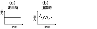
- FIG. 5 is a diagram showing time series data of acceleration when the vertical axis is output and the horizontal axis is time, (a) is a diagram showing steady-state data, and (b) is an additional graph. It is a figure which shows the data at the time of an earthquake.
- the mechanical seismic device 100 has a simple structure, can be easily reduced in price, and does not require standby power because of mechanical operation. However, since the horizontal dependency at the time of installation is very large, it becomes impossible to operate depending on the level of installation, and since it is a mechanical contact, there is a problem that the number of operations is limited.
- the acceleration sensor type seismic device 200 does not need to consider the horizontal dependency at the time of installation, and the magnitude of the vibration itself can be known in time series, and an ultrasensitive product can be easily made. it can. However, it is generally expensive and often overspec (excess performance). In addition, complicated signal processing is required, and accordingly, standby power is consumed by a driver and a microcomputer, resulting in a problem of increased power consumption.
- the present invention has little dependency on horizontality, the number of operations is semi-permanent, is not over-spec, does not require complicated signal processing, is inexpensive, and has low power consumption.
- the issue is to provide a seismic device.
- the invention described in claim 1 A spherical container; A liquid filled in the container leaving an air space in a part of the container; A high-sensitivity thermosensitive element disposed in the container in a state immersed in the liquid, By self-heating by the measurement current of the high-sensitivity thermosensitive element, the liquid is heated to form a high-temperature region around the high-sensitivity thermosensitive element, It is a seismometer that detects a decrease in temperature around the high-sensitivity thermosensitive element due to the flow of the liquid during vibration.
- the invention described in claim 2 The seismic sensor according to claim 1, wherein the high-sensitivity temperature sensing element is disposed in the vicinity of a spherical center of the spherical container.
- the invention according to claim 3 The seismic device according to claim 1 or 2, wherein the liquid is a liquid having a low vapor pressure.
- the invention according to claim 4 The seismic device according to any one of claims 1 to 3, further comprising a circuit that recognizes a temperature change of the high-sensitivity thermosensitive element.
- the invention described in claim 5 A spherical container; A liquid filled in the container leaving an air space in a part of the container; A high-sensitivity pressure-sensitive element disposed in the container in a state immersed in the liquid, It is a seismic device that detects a change in pressure applied to the high-sensitivity pressure-sensitive element due to the flow of the liquid during vibration.
- the invention described in claim 6 The seismic sensor according to claim 5, wherein the high-sensitivity pressure-sensitive element is disposed in the vicinity of a spherical center of the spherical container.
- the invention according to claim 8 provides: 8.
- FIG. 1 is a figure which shows typically the seismic device which concerns on the 1st Embodiment of this invention. It is a figure which shows typically the seismic device which concerns on the 2nd Embodiment of this invention. It is the figure which showed the mechanical type seismic device typically, Comprising: (a) is a figure which shows the state at the time of a steady state, (b) is a figure which shows the state at the time of an earthquake. It is a block diagram of an accelerometer of an acceleration sensor type. It is a figure which shows the time series data of the acceleration when taking an output on a vertical axis
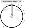
- FIG. 1 is a diagram schematically showing a seismic device according to the first embodiment of the present invention.
- the seismic device 1 includes a spherical container 2, a liquid 3 filled in the container 2, a thermistor 5 that is a kind of a high-sensitivity thermosensitive element immersed in the liquid 3,
- a circuit unit 8 having a differentiating circuit, an amplifier circuit, and a temperature compensation circuit, and an informing means (not shown) for informing vibration by a detection signal of the thermistor 5 are provided.
- the high-sensitivity thermosensitive element it is also preferable to use a high-precision platinum resistance thermometer, a thermocouple, etc. in addition to the thermistor.
- Container 2 is an empty sphere.
- the material is preferably stainless steel, resin, glass or the like, but is not particularly limited as long as the liquid can be stably held.
- liquid 3 a liquid having a low vapor pressure such as silicone oil is used.
- An air space portion 4 is formed above the liquid 3 in the container 2 so that the liquid 3 has fluidity when the container 2 is vibrated.
- the thermistor 5 is disposed in the center of the container 2 in a state where it is connected to the lead wire 5a of the thermistor 5.
- the lead wire 5 a is connected to the circuit unit 8 through the sealing unit 7 formed in the upper part of the container 2. 2a is a through hole.
- a flow stopper 6 is disposed around the lead wire 5a.
- the flow stopper 6 is formed of a hollow tube having a predetermined strength, the lead wire 5 a is inserted inside, and is fixed to the container 2 by the sealing portion 7.
- the sealing part 7 is sealed using a material corresponding to the material of the spherical container. For example, if the container is made of resin or stainless steel, resin sealing or the like is used. If the container is made of glass, glass sealing or the like is used.
- the flow stop 6 prevents the position of the thermistor 5 from moving due to the fluid pressure of the liquid 3 even when the container 2 shakes during the vibration. When the lead wire 5a having strength is used, the flow stopper 6 is not necessary.
- the thermistor 5 is made to be able to recognize the temperature difference between the steady state and the shaking state by constantly passing a measurement current.
- the thermistor 5 causes self-heating due to the measurement current and heats the liquid 3 around the thermistor 5.
- a high temperature region (in the region indicated by a one-dot chain line in FIG. 1) is formed around the thermistor 5, and the thermistor 5 detects the high temperature.
- a highly sensitive temperature sensitive element such as a thermistor is immersed in a liquid in a spherical container provided with an air space at the upper part, and the flow of the liquid A method using the temperature change of the high-sensitivity thermosensitive element is adopted. And even if a seismoscope shakes at the time of an earthquake, the air space part is always above and the highly sensitive temperature sensing element is always immersed in the liquid.
- the container is spherical, accurate detection is possible regardless of the installation direction.
- the high-sensitivity thermosensitive element is disposed in the vicinity of the sphere center of a spherical container, the direction dependency with respect to the shaking direction is completely eliminated, so that extremely accurate detection is possible.
- the seismic device has not only the horizontal dependency of the installation but also the direction dependency with respect to the shaking direction, so that extremely accurate detection is possible.
- the signal from the high-sensitivity thermosensitive element only needs to be processed by a simple circuit such as a differentiation circuit, amplification circuit, and temperature compensation circuit. Since the power consumption is low and the operation can be performed at 100 ⁇ W or less, the battery can be operated for a long time.
- the liquid heating method by self-heating using the measurement current of the high-sensitivity thermosensitive element is adopted, and the structure is simple such that the high-sensitivity thermosensitive element is simply immersed in the liquid.
- the cost is low, and only a change in temperature during steady state and during shaking is detected, so that complicated signal processing as in the acceleration sensor type is not required.
- FIG. FIG. 2 is a diagram schematically showing a seismic device according to the second embodiment of the present invention.
- the seismic device 1 includes a spherical container 2, a liquid 3 filled in the container 2, and a piezoelectric element 5 ′ which is a kind of high-sensitivity pressure-sensitive element immersed in the liquid 3.
- a circuit unit 8 having a differentiating circuit, an amplifying circuit, and a temperature compensation circuit, and a notifying means (not shown) for notifying vibration by a detection signal of the piezoelectric element 5 ′.
- Container 2 is an empty sphere.
- the material is preferably stainless steel, resin, glass or the like, but is not particularly limited as long as the liquid can be stably held.
- liquid 3 a liquid having a low vapor pressure such as silicone oil is used.
- An air space portion 4 is formed above the liquid 3 in the container 2 so that the liquid 3 has fluidity when the container 2 is vibrated.
- the piezoelectric element 5 ′ is arranged at the center of the container 2 in a state of being connected to the lead wire 5 a of the piezoelectric element 5 ′.
- the lead wire 5 a is connected to the circuit unit 8 through the sealing unit 7 formed in the upper part of the container 2. 2a is a through hole.
- a flow stopper 6 is disposed around the lead wire 5a.
- the flow stopper 6 is formed of a hollow tube having a predetermined strength, the lead wire 5 a is inserted inside, and is fixed to the container 2 by the sealing portion 7.
- the sealing part 7 is sealed using a material corresponding to the material of the spherical container. For example, if the container is made of resin or stainless steel, resin sealing or the like is used. If the container is made of glass, glass sealing or the like is used.
- the flow stop 6 prevents the position of the piezoelectric element 5 ′ from moving due to the fluid pressure of the liquid 3 even when the container 2 is shaken during the vibration. When the lead wire 5a having strength is used, the flow stopper 6 is not necessary.
- a constant pressure corresponding to the liquid depth is constantly applied to the piezoelectric element 5 ′.
- the piezoelectric element 5 ′ is further temperature-dependent, so the temperature compensation circuit corrects the temperature change error, and the pressure change is corrected. Recognize with high accuracy, and notify the supervisor appropriately through the notification means.
- a piezoelectric element can be preferably used as described above.
- the piezoelectric element is not limited to the piezoelectric element, and a quartz vibrator whose resonance frequency changes with pressure can also be preferably used.
- a highly sensitive pressure sensitive element such as a piezoelectric element is immersed in a liquid in a spherical container provided with an air space at the top, and the liquid
- a method that utilizes a pressure change of a high-sensitivity pressure-sensitive element due to flow is employed. And even if a shaker shakes at the time of an earthquake, the air space part is always above and the highly sensitive pressure sensitive element is always immersed in the liquid.
- the container is spherical, accurate detection is possible regardless of the installation direction.
- the high-sensitivity pressure-sensitive element is disposed in the vicinity of the spherical center of the spherical container, the direction dependency with respect to the shaking direction is completely eliminated, so that extremely accurate detection is possible.
- the seismic device has not only the horizontal dependency of the installation but also the direction dependency with respect to the shaking direction, so that extremely accurate detection is possible.
- the signal from the high-sensitivity pressure-sensitive element need only be processed by a simple circuit such as a differentiation circuit, amplification circuit, and temperature compensation circuit. Since the power consumption is low and the operation can be performed at 100 ⁇ W or less, the battery can be operated for a long time.
- the container is filled with the liquid in a state where an air space is left in a part of the container, and the earthquake disposed in the container in a state immersed in the liquid.
Landscapes
- Physics & Mathematics (AREA)
- Life Sciences & Earth Sciences (AREA)
- Engineering & Computer Science (AREA)
- Acoustics & Sound (AREA)
- Environmental & Geological Engineering (AREA)
- Geology (AREA)
- Remote Sensing (AREA)
- General Life Sciences & Earth Sciences (AREA)
- General Physics & Mathematics (AREA)
- Geophysics (AREA)
- Geophysics And Detection Of Objects (AREA)
- Measurement Of Mechanical Vibrations Or Ultrasonic Waves (AREA)
Abstract
球状の容器と、容器に、容器の一部に空気空間を残した状態で充填された液体と、液体に浸漬した状態で前記容器内に配置された高感度感温素子または高感度感圧素子を備えており、加震時の液体の流動による温度または圧力の変化を検知することを特徴とする感震器。高感度感温素子または高感度感圧素子が、球状の容器の球心近傍に配置されていること。液体が、蒸気圧の低い液体であること。高感度感温素子の温度変化または、高感度感圧素子に加わる圧力の変化を認識する回路を備えていること。
Description
本発明は、地震等の加震時の振動を検知する感震器に関する。
この種の感震器としては、機械型の感震器や加速度センサ型の感震器が知られている(例えば、特許文献1、特許文献2)。
図3は、従来の機械型の感震器を模式的に示した図であって、(a)は定常時の状態を示す図、(b)は加震時の状態を示す図である。図3に示すように、機械型の感震器100は、電気接点101を鋼球102により開閉するように構成されている。そして、定常時は、図3(a)に示すように、電気接点101が閉の状態にされており、加震時に、図3(b)に示すように、鋼球102の移動により電気接点101が開放されるように構成されている。
図4は、加速度センサ型の感震器のブロック図である。図4に示すように、加速度センサ型の感震器200は、加速度センサ201およびセンサドライバ・マイコン202を備えており、図5に示すように、加震時には、加震の大きさそのものを時系列で測定して出力するように構成されている。なお、図5は、縦軸に出力をとり、横軸に時間をとったときの加速度の時系列データを示す図であり、(a)は定常時のデータを示す図、(b)は加震時のデータを示す図である。
機械式の感震器100は、単純構造で、低価格化が容易となり、また、機械動作であるため、待機電力が不要になる。しかし、設置時の水平依存性が非常に大きいため、設置の水平度によっては動作不能になり、また、機械式接点であるため、動作回数が限定されるという問題がある。
一方、加速度センサ型の感震器200は、設置時の水平依存性を考慮しなくてもよく、また、加震の大きさそのものが時系列に分かり、超高感度品も容易に作ることができる。しかし、一般的に高価であり、オーバースペック(過剰性能)になることが多い。また、複雑な信号処理が必要であり、これに伴い待機電力がドライバ、マイコンで多く消費されるため、消費電力も多くなるという問題がある。
本発明は、これらの問題に鑑み、水平度依存性が少なく、動作回数が半永久的であり、さらに、オーバースペックにならず、また複雑な信号処理を必要とせず、安価で、消費電力も少ない感震器を提供することを課題とする。
本発明者は、鋭意検討の結果、以下に示す発明により、上記の課題が解決できることを見出し、本発明を完成するに至った。
以下、各請求項の発明を説明する。
請求項1に記載の発明は、
球状の容器と、
前記容器に、前記容器の一部に空気空間を残した状態で充填された液体と、
前記液体に浸漬した状態で前記容器内に配置された高感度感温素子と
を備えており、
前記高感度感温素子の測定電流による自己発熱により、前記液体を加熱して前記高感度感温素子の周囲に高温域を形成し、
加震時の前記液体の流動による前記高感度感温素子周囲の温度の低下を検知する
ことを特徴とする感震器である。
球状の容器と、
前記容器に、前記容器の一部に空気空間を残した状態で充填された液体と、
前記液体に浸漬した状態で前記容器内に配置された高感度感温素子と
を備えており、
前記高感度感温素子の測定電流による自己発熱により、前記液体を加熱して前記高感度感温素子の周囲に高温域を形成し、
加震時の前記液体の流動による前記高感度感温素子周囲の温度の低下を検知する
ことを特徴とする感震器である。
請求項2に記載の発明は、
前記高感度感温素子が、前記球状の容器の球心近傍に配置されている
ことを特徴とする請求項1に記載の感震器である。
前記高感度感温素子が、前記球状の容器の球心近傍に配置されている
ことを特徴とする請求項1に記載の感震器である。
請求項3に記載の発明は、
前記液体が、蒸気圧の低い液体である
ことを特徴とする請求項1または請求項2に記載の感震器である。
前記液体が、蒸気圧の低い液体である
ことを特徴とする請求項1または請求項2に記載の感震器である。
請求項4に記載の発明は、
前記高感度感温素子の温度変化を認識する回路を備えている
ことを特徴とする請求項1ないし請求項3のいずれか1項に記載の感震器である。
前記高感度感温素子の温度変化を認識する回路を備えている
ことを特徴とする請求項1ないし請求項3のいずれか1項に記載の感震器である。
請求項5に記載の発明は、
球状の容器と、
前記容器に、前記容器の一部に空気空間を残した状態で充填された液体と、
前記液体に浸漬した状態で前記容器内に配置された高感度感圧素子と
を備えており、
加震時の前記液体の流動により前記高感度感圧素子に加わる圧力の変化を検知する
ことを特徴とする感震器である。
球状の容器と、
前記容器に、前記容器の一部に空気空間を残した状態で充填された液体と、
前記液体に浸漬した状態で前記容器内に配置された高感度感圧素子と
を備えており、
加震時の前記液体の流動により前記高感度感圧素子に加わる圧力の変化を検知する
ことを特徴とする感震器である。
請求項6に記載の発明は、
前記高感度感圧素子が、前記球状の容器の球心近傍に配置されている
ことを特徴とする請求項5に記載の感震器である。
前記高感度感圧素子が、前記球状の容器の球心近傍に配置されている
ことを特徴とする請求項5に記載の感震器である。
請求項7に記載の発明は、
前記液体が、蒸気圧の低い液体である
ことを特徴とする請求項5または請求項6に記載の感震器である。
前記液体が、蒸気圧の低い液体である
ことを特徴とする請求項5または請求項6に記載の感震器である。
請求項8に記載の発明は、
前記高感度感圧素子に加わる圧力の変化を認識する回路を備えている
ことを特徴とする請求項5ないし請求項7のいずれか1項に記載の感震器である。
前記高感度感圧素子に加わる圧力の変化を認識する回路を備えている
ことを特徴とする請求項5ないし請求項7のいずれか1項に記載の感震器である。
本発明によれば、水平度依存性が少なく、動作回数が半永久的であり、さらに、オーバースペックにならず、また複雑な信号処理を必要とせず、安価で、消費電力も少ない感震器を提供することできる。
以下、本発明を実施の形態に基づいて説明する。
(A)第1の実施の形態
1.感震器の構成
図1は、本発明の第1の実施の形態に係る感震器を模式的に示す図である。図1に示すように、感震器1は、球状の容器2と、容器2に充填される液体3と、液体3中に漬浸される高感度感温素子の一種であるサーミスタ5と、微分回路、増幅回路および温度補償回路を有する回路部8と、サーミスタ5の検知信号により振動を報知する報知手段(図示省略)とを備えている。高感度感温素子としては、サーミスタの外、高精度白金測温抵抗体、熱電対などを用いることも好ましい。
1.感震器の構成
図1は、本発明の第1の実施の形態に係る感震器を模式的に示す図である。図1に示すように、感震器1は、球状の容器2と、容器2に充填される液体3と、液体3中に漬浸される高感度感温素子の一種であるサーミスタ5と、微分回路、増幅回路および温度補償回路を有する回路部8と、サーミスタ5の検知信号により振動を報知する報知手段(図示省略)とを備えている。高感度感温素子としては、サーミスタの外、高精度白金測温抵抗体、熱電対などを用いることも好ましい。
容器2は、空球体である。材質としては、ステンレス、樹脂、ガラス等が好ましいが、液体を安定して保持できる限り、特に制限されない。
液体3としては、シリコーン油等の蒸気圧の低い液体が使用される。
容器2内の液体3の上部には、空気空間部4が形成されており、容器2が加震されたときに液体3に流動性を持たせている。
サーミスタ5は、サーミスタ5のリード線5aに接続された状態で容器2の中心部に配置されている。リード線5aは、容器2の上部に形成された封止部7を通って回路部8に接続されている。なお、2aは貫通孔である。
リード線5aの周囲には、流れ止め6が配置されている。流れ止め6は、所定の強度を有する中空管で形成され、内部にリード線5aが挿通され、容器2に封止部7により固定されている。封止部7は、球状の容器の材質に応じた材料を用いて封止がされている。例えば、容器が樹脂製あるいはステンレス製であれば、樹脂封止などが、ガラス製の容器であれば、ガラス封止などが採用される。
流れ止め6は、加震時に容器2が揺れた場合でも、サーミスタ5の位置が液体3の流体圧により移動しないようにしている。なお、強度のあるリード線5aを使用する場合は、流れ止め6は不要になる。
2.感震器の動作
前記のように構成される感震器1の基本的な動作を説明する。
前記のように構成される感震器1の基本的な動作を説明する。
サーミスタ5には、常に測定電流が流されることにより、定常時と加震時における温度差を認識できるようになっている。
このため、サーミスタ5は、測定電流による自己発熱を起こしてサーミスタ5の周囲の液体3を加熱する。
したがって、定常時には、サーミスタ5の周囲に高温域(図1の一点鎖線で示す領域内)を形成して、サーミスタ5は高温度を検知することになる。
一方、加震時には、液体3が容器2の振動により流動するため、高温域の液体3とその周囲にあった低温域の液体3とが混ざり合う。このため、サーミスタ5の周囲の高温域の液体3の温度が低下する。そして、サーミスタ5の定常時と加震時における温度変化量を微分回路で検出し、増幅回路で増幅した後、温度補償回路で温度変化の誤差を修正し、定常時の温度との差を精度高く認識し、適宜、報知手段を通じて監視者に報知する。
3.本実施の形態の効果
(1)本実施の形態においては、上部に空気空間部が設けられた球状の容器内の液体中にサーミスタのような高感度感温素子を浸漬して、液体の流動による高感度感温素子の温度変化を利用する方式が採用されている。そして、加震時に感震器が揺れた場合でも、空気空間部は常に上方にあり、高感度感温素子は常に液体中に浸漬されている。
(1)本実施の形態においては、上部に空気空間部が設けられた球状の容器内の液体中にサーミスタのような高感度感温素子を浸漬して、液体の流動による高感度感温素子の温度変化を利用する方式が採用されている。そして、加震時に感震器が揺れた場合でも、空気空間部は常に上方にあり、高感度感温素子は常に液体中に浸漬されている。
このため、地震になどによる揺れの方向に影響されず、常に正確な検知が可能となる。即ち、従来の機械型の感震器の場合、水平に設置した場合でも、揺れの方向が上下の場合と、左右の場合とで検知結果に差が出やすい。また、加速度センサ型の感震器の場合、設置時の水平依存性は比較的考慮しなくてもよいが、揺れ方向が上下の場合と、左右の場合とで検知結果に差が出やすい。しかし、本実施の形態においては、液体の流動による高感度感温素子の温度変化を利用する方式が採用されているため、揺れの方向に影響されず、常に正確な検知が可能となる。
さらに、容器が球状であるため、設置方向に拘わらず、正確な検知が可能になる。特に、高感度感温素子が、球状の容器の球心近傍に配置されている場合には、揺れ方向に対する方向依存性が全くなくなるため、極めて正確な検知が可能となる。
このように、本実施の形態の感震器には、設置の水平依存性だけでなく、揺れ方向に対する方向依存性が全くなくなるため、極めて正確な検知が可能となる。
(2)定常時と加震時の温度変化が認識できるだけでよいため、高感度感温素子からの信号は、微分回路、増幅回路、温度補償回路程度の簡単な回路で処理するだけで済み、消費電力が少なく100μW以下での動作可能となるため、乾電池で長時間動作が可能となる。
(3)高感度感温素子の測定電流による自己発熱により液体を加熱しているため、別途加熱手段を設ける必要がなく、構造が簡単であり、消費電力も少なくて済む。
(4)機械式接点をなくす一方、容器内の液体に浸漬した高感度感温素子により加震時の温度の低下を検知する単純な方式であるため、動作回数が半永久的になる。
(5)前記の通り、高感度感温素子の測定電流を利用した自己発熱による液体加熱方式を採用しており、高感度感温素子を液体に浸漬させるだけの単純な構造であり、処理回路も単純な回路で済むため、安価であり、定常時と加震時の温度変化を検知するだけであるため、加速度センサ型のような複雑な信号処理を必要としない。
(B)第2の実施の形態
1.感震器の構成
図2は、本発明の第2の実施の形態に係る感震器を模式的に示す図である。図2に示すように、感震器1は、球状の容器2と、容器2に充填される液体3と、液体3中に浸漬される高感度感圧素子の一種である圧電素子5´と、微分回路、増幅回路および温度補償回路を有する回路部8と、圧電素子5´の検知信号により振動を報知する報知手段(図示省略)とを備えている。
1.感震器の構成
図2は、本発明の第2の実施の形態に係る感震器を模式的に示す図である。図2に示すように、感震器1は、球状の容器2と、容器2に充填される液体3と、液体3中に浸漬される高感度感圧素子の一種である圧電素子5´と、微分回路、増幅回路および温度補償回路を有する回路部8と、圧電素子5´の検知信号により振動を報知する報知手段(図示省略)とを備えている。
容器2は、空球体である。材質としては、ステンレス、樹脂、ガラス等が好ましいが、液体を安定して保持できる限り、特に制限されない。
液体3としては、シリコーン油等の蒸気圧の低い液体が使用される。
容器2内の液体3の上部には、空気空間部4が形成されており、容器2が加震されたときに液体3に流動性を持たせている。
圧電素子5´は、圧電素子5´のリード線5aに接続された状態で容器2の中心部に配置されている。リード線5aは、容器2の上部に形成された封止部7を通って回路部8に接続されている。なお、2aは貫通孔である。
リード線5aの周囲には、流れ止め6が配置されている。流れ止め6は、所定の強度を有する中空管で形成され、内部にリード線5aが挿通され、容器2に封止部7により固定されている。封止部7は、球状の容器の材質に応じた材料を用いて封止がされている。例えば、容器が樹脂製あるいはステンレス製であれば、樹脂封止などが、ガラス製の容器であれば、ガラス封止などが採用される。
流れ止め6は、加震時に容器2が揺れた場合でも、圧電素子5´の位置が液体3の流体圧により移動しないようにしている。なお、強度のあるリード線5aを使用する場合は、流れ止め6は不要になる。
2.感震器の動作
前記のように構成される感震器1の基本的な動作を説明する。
前記のように構成される感震器1の基本的な動作を説明する。
圧電素子5´には、常に液深に応じた一定の圧力が持続的に加わっている。
加震時には、液体3が容器2の振動により流動するため、圧電素子5´に対して流動抵抗が発生する。この流動抵抗は微少な圧力差を生み、前記した液深に応じて一定の圧力が持続的に加わっている圧電素子に対して、微少な差圧が加えられ、圧力の変化が生じる。この圧力の変化は圧電素子より変位信号として取り出すことができる。
そして、この圧力の変化量を微分回路で検出し、増幅回路で増幅した後、さらに圧電素子5´は温度依存性があるため、温度補償回路で温度変化の誤差を修正し、圧力の変化を精度高く認識し、適宜、報知手段を通じて監視者に報知する。
高感度感圧素子としては、前記のように圧電素子を好ましく用いることができるが、圧電素子には限られず、圧力によって共振周波数が変化する水晶振動子なども好ましく用いることができる。
水晶振動子を用いる場合には、水晶振動子を振動させるための電流を流しておき、水晶振動子の共振周波数を検知しておくことになる。そして、加震時には、液体3の流動により水晶振動子に加震による圧力が加わるため、水晶のひずみに応じて共振周波数が変化する。このため、この変化量を回路部8で検出することにより加震されたことを認識することができる。この場合も、圧力の変化量を微分回路で検出し、増幅回路で増幅し、さらに圧電素子と同様、温度補償回路で温度変化の誤差を修正することにより、圧力の変化を精度高く認識することができる。
3.本実施の形態の効果
(1)本実施の形態においては、上部に空気空間部が設けられた球状の容器内の液体中に圧電素子のような高感度感圧素子を浸漬して、液体の流動による高感度感圧素子の圧力変化を利用する方式が採用されている。そして、加震時に感震器が揺れた場合でも、空気空間部は常に上方にあり、高感度感圧素子は常に液体中に浸漬されている。
(1)本実施の形態においては、上部に空気空間部が設けられた球状の容器内の液体中に圧電素子のような高感度感圧素子を浸漬して、液体の流動による高感度感圧素子の圧力変化を利用する方式が採用されている。そして、加震時に感震器が揺れた場合でも、空気空間部は常に上方にあり、高感度感圧素子は常に液体中に浸漬されている。
このため、地震などによる揺れの方向に影響されず、常に正確な検知が可能となる。即ち、従来の機械型の感震器の場合、水平に設置した場合でも、揺れの方向が上下の場合と、左右の場合とで検知結果に差が出やすい。また、加速度センサ型の感震器の場合、設置時の水平依存性は比較的考慮しなくてもよいが、揺れ方向が上下の場合と、左右の場合とで検知結果に差が出やすい。しかし、本実施の形態においては、液体の流動による高感度感圧素子の圧力変化を利用する方式が採用されているため、揺れの方向に影響されず、常に正確な検知が可能となる。
さらに、容器が球状であるため、設置方向に拘わらず、正確な検知が可能になる。特に、高感度感圧素子が、球状の容器の球心近傍に配置されている場合には、揺れ方向に対する方向依存性が全くなくなるため、極めて正確な検知が可能となる。
このように、本実施の形態の感震器には、設置の水平依存性だけでなく、揺れ方向に対する方向依存性が全くなくなるため、極めて正確な検知が可能となる。
(2)定常時と加震時の圧力変化が認識できるだけでよいため、高感度感圧素子からの信号は、微分回路、増幅回路、温度補償回路程度の簡単な回路で処理するだけで済み、消費電力が少なく100μW以下での動作可能となるため、乾電池で長時間動作が可能となる。
(3)機械式接点をなくす一方、容器内の液体に浸漬した高感度感圧素子により加震時の圧力変化を検知する単純な方式であるため、動作回数が半永久的になる。
(4)前記の通り、高感度感圧素子を液体に浸漬させるだけの単純な構造であり、処理回路も単純な回路で済むため、安価であり、定常時と加震時の圧力変化を検知するだけであるため、加速度センサ型のような複雑な信号処理を必要としない。
このように本発明の実施の形態によれば、容器に、前記容器の一部に空気空間を残した状態で充填された液体と、前記液体に浸漬した状態で前記容器内に配置された地震などによる揺れに伴う前記容器内の液体の状態変化を検知する素子とを備えているため、地震などによる揺れの方向に影響されず、極めて正確な検知が可能となる。
以上、本発明を実施の形態に基づいて説明したが、本発明は上記の実施の形態に限定されるものではない。本発明と同一および均等の範囲内において、上記の実施の形態に対して種々の変更を加えることができる。
1 感震器
2 容器
2a 貫通孔
3 液体
4 空気空間部
5 サーミスタ
5´ 圧電素子
5a リード線
6 流れ止め
7 封止部
8 回路部
100 機械型の感震器
101 電気接点
102 鋼球
200 加速度センサ型の感震器
201 加速度センサ
202 センサドライバ・マイコン
2 容器
2a 貫通孔
3 液体
4 空気空間部
5 サーミスタ
5´ 圧電素子
5a リード線
6 流れ止め
7 封止部
8 回路部
100 機械型の感震器
101 電気接点
102 鋼球
200 加速度センサ型の感震器
201 加速度センサ
202 センサドライバ・マイコン
Claims (8)
- 球状の容器と、
前記容器に、前記容器の一部に空気空間を残した状態で充填された液体と、
前記液体に浸漬した状態で前記容器内に配置された高感度感温素子と
を備えており、
前記高感度感温素子の測定電流による自己発熱により、前記液体を加熱して前記高感度感温素子の周囲に高温域を形成し、
加震時の前記液体の流動による前記高感度感温素子周囲の温度の低下を検知する
ことを特徴とする感震器。 - 前記高感度感温素子が、前記球状の容器の球心近傍に配置されている
ことを特徴とする請求項1に記載の感震器。 - 前記液体が、蒸気圧の低い液体である
ことを特徴とする請求項1または請求項2に記載の感震器。 - 前記高感度感温素子の温度変化を認識する回路を備えている
ことを特徴とする請求項1ないし請求項3のいずれか1項に記載の感震器。 - 球状の容器と、
前記容器に、前記容器の一部に空気空間を残した状態で充填された液体と、
前記液体に浸漬した状態で前記容器内に配置された高感度感圧素子と
を備えており、
加震時の前記液体の流動により前記高感度感圧素子に加わる圧力の変化を検知する
ことを特徴とする感震器。 - 前記高感度感圧素子が、前記球状の容器の球心近傍に配置されている
ことを特徴とする請求項5に記載の感震器。 - 前記液体が、蒸気圧の低い液体である
ことを特徴とする請求項5または請求項6に記載の感震器。 - 前記高感度感圧素子に加わる圧力の変化を認識する回路を備えている
ことを特徴とする請求項5ないし請求項7のいずれか1項に記載の感震器。
Applications Claiming Priority (4)
| Application Number | Priority Date | Filing Date | Title |
|---|---|---|---|
| JP2011046628A JP4750910B1 (ja) | 2011-03-03 | 2011-03-03 | 感震器 |
| JP2011-046628 | 2011-03-03 | ||
| JP2011160778A JP5054837B1 (ja) | 2011-07-22 | 2011-07-22 | 感震器 |
| JP2011-160778 | 2011-07-22 |
Publications (1)
| Publication Number | Publication Date |
|---|---|
| WO2012117589A1 true WO2012117589A1 (ja) | 2012-09-07 |
Family
ID=46757543
Family Applications (1)
| Application Number | Title | Priority Date | Filing Date |
|---|---|---|---|
| PCT/JP2011/069683 Ceased WO2012117589A1 (ja) | 2011-03-03 | 2011-08-31 | 感震器 |
Country Status (1)
| Country | Link |
|---|---|
| WO (1) | WO2012117589A1 (ja) |
Citations (5)
| Publication number | Priority date | Publication date | Assignee | Title |
|---|---|---|---|---|
| JPS62245930A (ja) * | 1986-04-18 | 1987-10-27 | Toshiba Corp | 輸送振動監視装置 |
| JPH01239426A (ja) * | 1988-03-19 | 1989-09-25 | Akashi Seisakusho Co Ltd | 感震器 |
| JPH0579896A (ja) * | 1991-09-24 | 1993-03-30 | Idec Izumi Corp | 感震装置 |
| JP2006105632A (ja) * | 2004-09-30 | 2006-04-20 | Daiwa House Ind Co Ltd | 感震器 |
| JP2007187577A (ja) * | 2006-01-13 | 2007-07-26 | Sharp Corp | 振動検出装置 |
-
2011
- 2011-08-31 WO PCT/JP2011/069683 patent/WO2012117589A1/ja not_active Ceased
Patent Citations (5)
| Publication number | Priority date | Publication date | Assignee | Title |
|---|---|---|---|---|
| JPS62245930A (ja) * | 1986-04-18 | 1987-10-27 | Toshiba Corp | 輸送振動監視装置 |
| JPH01239426A (ja) * | 1988-03-19 | 1989-09-25 | Akashi Seisakusho Co Ltd | 感震器 |
| JPH0579896A (ja) * | 1991-09-24 | 1993-03-30 | Idec Izumi Corp | 感震装置 |
| JP2006105632A (ja) * | 2004-09-30 | 2006-04-20 | Daiwa House Ind Co Ltd | 感震器 |
| JP2007187577A (ja) * | 2006-01-13 | 2007-07-26 | Sharp Corp | 振動検出装置 |
Similar Documents
| Publication | Publication Date | Title |
|---|---|---|
| JP5778619B2 (ja) | 圧力センサ | |
| US8997582B2 (en) | Method and apparatus for determining flow characteristics of a medium in a pipeline | |
| TWI470227B (zh) | 液體密度量測裝置 | |
| US9513150B2 (en) | Method for operating a coriolis mass flowmeter | |
| KR101920832B1 (ko) | 진동 계량기용 계량 센서의 확인 | |
| CN101135580A (zh) | 用于确定探测装置特性曲线的方法 | |
| WO2001044761A1 (fr) | Fluxmetre thermique a fonction discriminante vis a vis des fluides | |
| CN106104233A (zh) | 内部温度测量方法以及内部温度测量装置 | |
| CN104736994B (zh) | 获得在参考温度下的流动流体粘度的仪表电子设备和方法 | |
| CN103051285A (zh) | 用于修正压阻式振荡器的频率的温度相关性的电路和方法 | |
| US20230057869A1 (en) | Resonant frequency-based magnetic sensor at veering zone and method | |
| CN102686988B (zh) | 用于确定至少一个过程变量的设备 | |
| JP5355278B2 (ja) | 振動式密度計の校正パラメータ決定方法及び密度算出方法 | |
| JP4750910B1 (ja) | 感震器 | |
| Tang et al. | An electrothermally excited dual beams silicon resonant pressure sensor with temperature compensation | |
| CN111044095A (zh) | 一种用于罐式集装箱的多功能传感装置 | |
| Liu et al. | Research on temperature dependent characteristics and compensation methods for digital gyroscope | |
| WO2012117589A1 (ja) | 感震器 | |
| JP5054837B1 (ja) | 感震器 | |
| CN208818255U (zh) | 一种用于罐式集装箱的多功能传感装置 | |
| US20150300864A1 (en) | Liquid level sensor system | |
| JPH0515975B2 (ja) | ||
| CN107014453B (zh) | 用于运行科里奥利质量流量测量仪器的方法及对此的科里奥利质量流量测量仪器 | |
| CN210166258U (zh) | 一种磁流体热膨胀系数测量系统 | |
| CN110208132B (zh) | 一种磁流体热膨胀系数测量系统及方法 |
Legal Events
| Date | Code | Title | Description |
|---|---|---|---|
| 121 | Ep: the epo has been informed by wipo that ep was designated in this application |
Ref document number: 11860081 Country of ref document: EP Kind code of ref document: A1 |
|
| NENP | Non-entry into the national phase |
Ref country code: DE |
|
| 122 | Ep: pct application non-entry in european phase |
Ref document number: 11860081 Country of ref document: EP Kind code of ref document: A1 |