WO2012117606A1 - Recipient sous pression - Google Patents
Recipient sous pression Download PDFInfo
- Publication number
- WO2012117606A1 WO2012117606A1 PCT/JP2011/073867 JP2011073867W WO2012117606A1 WO 2012117606 A1 WO2012117606 A1 WO 2012117606A1 JP 2011073867 W JP2011073867 W JP 2011073867W WO 2012117606 A1 WO2012117606 A1 WO 2012117606A1
- Authority
- WO
- WIPO (PCT)
- Prior art keywords
- lid
- lid body
- opening
- operation lever
- claw
- Prior art date
- Legal status (The legal status is an assumption and is not a legal conclusion. Google has not performed a legal analysis and makes no representation as to the accuracy of the status listed.)
- Ceased
Links
Images


Classifications
-
- F—MECHANICAL ENGINEERING; LIGHTING; HEATING; WEAPONS; BLASTING
- F16—ENGINEERING ELEMENTS AND UNITS; GENERAL MEASURES FOR PRODUCING AND MAINTAINING EFFECTIVE FUNCTIONING OF MACHINES OR INSTALLATIONS; THERMAL INSULATION IN GENERAL
- F16J—PISTONS; CYLINDERS; SEALINGS
- F16J13/00—Covers or similar closure members for pressure vessels in general
- F16J13/02—Detachable closure members; Means for tightening closures
- F16J13/12—Detachable closure members; Means for tightening closures attached by wedging action by means of screw-thread, interrupted screw-thread, bayonet closure, or the like
-
- F—MECHANICAL ENGINEERING; LIGHTING; HEATING; WEAPONS; BLASTING
- F16—ENGINEERING ELEMENTS AND UNITS; GENERAL MEASURES FOR PRODUCING AND MAINTAINING EFFECTIVE FUNCTIONING OF MACHINES OR INSTALLATIONS; THERMAL INSULATION IN GENERAL
- F16J—PISTONS; CYLINDERS; SEALINGS
- F16J13/00—Covers or similar closure members for pressure vessels in general
- F16J13/16—Pivoted closures
- F16J13/20—Pivoted closures mounted by mobile fastening on swinging arms
Definitions
- the present invention relates to a pressure vessel that closes an opening of a can with a lid.
- the pressure vessel includes a can body that houses an object inside and a lid body that closes an opening of the can body.
- the pressure vessel can be used, for example, to apply pressure to the sealed object to expel the air in the seal, sterilize the object by pressurizing and heating the inside, and pressurize the object. -Used for various purposes, such as for environmental testing of objects in a heated special environment.
- Patent Document 1 describes a locking mechanism between a can body and a lid body of a pressure vessel.
- the opening of the pressure vessel is provided with a clamp ring having a plurality of lugs formed so as to project radially outward, and the lid is arranged so as to rotate to the lid and inwardly.
- a lock ring having a plurality of lugs formed to project is provided.
- Patent Document 1 describes that when a pressure vessel is closed, a lock ring of a lid is driven by a hydraulic control system.
- Patent Document 2 discloses a pressure vessel as an environmental test apparatus.
- the pressure vessel of Patent Document 2 there is no particular description about the locking mechanism between the lid and the can.
- a handle-like structure for the operator to open and close the lid by hand is illustrated in the center of the lid. Has been.
- Patent Document 2 a handle for manually opening and closing the lid is illustrated.
- the handle can be rotated with both hands to lock the lid and the can, and the lid can be opened and closed with the handle.
- both hands In the conventional technology described above, in the pressure vessel that manually opens and closes the lid, both hands must be used, and both hands must be used to lock the lid and the can. However, there is a problem that the burden on the operator is heavy if the lid and the can body are always locked and unlocked using both hands and the lid is opened and closed with both hands.
- the present invention has been made to solve the above-mentioned problems, and the object of the present invention is to perform opening and closing of the lid and locking of the lid and the can with one hand so as not to burden the operator.
- An object of the present invention is to provide a pressure vessel capable of performing
- a pressure vessel comprising a can body in which an opening is formed, a lid that closes the opening of the can, and a hinge portion for opening and closing the lid.
- the peripheral edge of the opening of the can body is provided with a plurality of claw portions projecting inward
- the lid body includes a lid body provided with a plurality of claw portions projecting outward, a hinge And a support plate that supports the lid body so as to be rotatable about the center of the lid body as an axis.
- One end is fixed to the lid body and the other end is formed as a gripping part that is held by an operator.
- An operation lever that is arranged in parallel to the opening surface of the opening of the can body and can be operated so that the lid body rotates about the center of the lid body by moving the other end up and down. It is characterized by being provided.
- the operator can turn the lid body by raising or lowering the other end of the operation lever.
- the lid body and the can body are locked when the claw portion of the lid body and the claw portion on the periphery of the opening of the can body come into meshing positions.
- the lock is released when the claw portion of the lid body and the claw portion at the periphery of the opening of the can body are not engaged with each other.
- the operation lever by pulling the operation lever in a state where the lock is released (in a direction away from the can body), the lid body is rotated by the hinge portion, and the lid body can be opened.
- a stopper is provided so that the operation lever becomes inoperable when the operation lever is located at the two places. It is good also as a feature. According to this configuration, the operation lever can be prevented from operating easily, and safety can be ensured.
- the stopper is fixed to the support plate and is formed in an elongated shape along the operation direction of the operation lever, and the operation lever penetrates and can move inside along the operation direction of the operation lever.
- a guide plate having a long hole formed, a pin-like member provided on the operation lever and urged against a surface of the guide plate via a biasing means; and the lock position; It is good also as having the accommodation recessed part in which the said pin-shaped member is accommodated formed in the predetermined position of the guide plate corresponding to the said lock release position. According to this configuration, since the pin-shaped member is converged in the storage recess, the operation lever can be prevented from moving from this position, so that the operation lever can be prevented from operating easily and safety can be improved. Can be secured.
- the operation lever may be provided with a stopper release button that moves the pin-shaped member away from the guide plate side against the urging force of the urging means. According to this configuration, it is possible to operate the operation lever while pressing the stopper release button with one hand, so that an easy operation can be performed without increasing the burden on the operator.
- the lid can be opened and closed and the lid and the can can be locked with one hand, so the burden on the operator can be reduced.
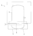
- FIG. 1 shows a front view showing the entire pressure vessel of the present embodiment
- FIG. 2 shows a side view of the entire pressure vessel.
- the pressure vessel 30 includes a bottomed cylindrical can body 34 and a lid body 36 for closing the opening 35 of the can body 34.
- the can 34 is arranged horizontally, and the opening 35 also faces the horizontal direction.
- the periphery of the can body 34 is covered with a main body exterior 38, and the periphery of the lid body 36 is covered with a lid body exterior 37.
- the lid 36 is locked and unlocked from the can 34 by an operation lever 88 as will be described later, and by pulling the operation lever 88 away from the can 34 (front side in FIG. 1), The lid 36 can be opened from the can 34 by rotating the hinge 42.
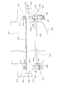
- FIG. 3 illustrates a locking mechanism between the can body and the lid body.
- 4 is a front view of the lid
- FIG. 5 is a plan view of the lid.
- a flange portion 44 that protrudes outward is formed on the periphery of the opening 35 of the can 34.
- a plurality of claw portions 46 projecting inward are provided on the outer edge of the flange portion 44.
- a gap 45 is formed between the claw portion 46 and the flange portion 44, and the end of the lid main body 50 of the lid body 36 is disposed in the gap 45.
- the lid body 36 includes a support plate 48 and a lid body 50.
- the lid body 50 is a member for actually closing the opening 35 of the can 34 on the can 34 side, and has a shape that engages with the claw 46 on the periphery of the opening 35. That is, the end surface of the lid body 50 on the side of the can body 34 is formed with a plurality of claw portions 52 having a thickness that can enter the inside of the claw portion 46 at the periphery of the opening 35 of the can body 34.
- the claw portions are engaged with each other, and the lid body 36 and the can body 34 are locked.
- the lid body 50 can rotate around the hinge portion 42 so as to be separated from the opening 35 of the can 34 and open the opening 35.
- the lid body 50 is formed with a curved portion 53 protruding in the opposite direction to the can body 34 on the side away from the can body 34 in plan view, and the above-described claw portion 52 is formed on the can body 34 side. ing.
- the lid body 50 is substantially circular when viewed from the front.
- the lid body 50 is rotatably held around the center O of the circle of the lid body passing through the longitudinal direction of the can 34 by the support plate 48 at a substantially intermediate position between the curved surface portion 53 and the claw portion 52. Yes.
- the support plate 48 is provided with a plurality of holding members 55 that rotatably hold the lid body 50.
- the holding member 55 includes a bearing 56 that holds the rotation end surface of the lid body 50, a presser pin 57 that fixes the bearing 56 to the support plate 48, and a nut 58 that tightens the presser pin 57 and the bearing 56. ing.
- the presser pin 57 is inserted into a mounting hole 59 formed at a predetermined position of the support plate 48.
- the holding members 55 are provided at three locations around the lid body 50, and the lid body 50 is supported by the support plate 48 by the three holding members 55. By operating an operation lever 88 to be described later, the lid body 50 can be rotated with respect to the support plate 48 in a vertical plane parallel to the opening surface of the opening 35 while being held by the bearing 56.
- the diameter of the mounting hole 59 of the support plate 48 is formed to be larger than the presser pin 57 so that there is a gap with the outer peripheral surface of the inserted presser pin 57.
- Each holding member 55 is provided with an adjustment screw 60 for adjusting and fixing the position of the presser pin 57 in the attachment hole 59.
- the adjustment screw 60 is arranged from the outside of the circle of the lid body to the inside. The tip of the adjustment screw 60 comes into contact with the side surface of the presser pin 57 in the mounting hole 59.
- the adjustment screw 60 is further tightened, the entire holding member 55 moves inward of the circle.
- the position of the lid main body 50 (position in a plane parallel to the opening surface of the opening 35) can be adjusted. Thereby, it can adjust so that the nail
- the lid body 36 has a plurality of push / angle adjustment members 64 that can push the lid body 50 into the support plate 48 and adjust the angle with respect to a plane parallel to the opening surface of the opening 35 of the lid body 50.
- the push-in / angle adjusting member 64 includes a pin 65 having a thread 65 a formed at the tip, and a compression coil spring 66 disposed around the pin 65.
- the pin 65 is housed in an arc groove 67 formed in the support plate 48, and the tip end portion on which the thread 65a is formed is screwed and fixed to the lid body 50.
- a retaining nut 69 is attached to the rear end side of the pin 65.
- a compression coil spring 66 is disposed between the nut 69 and the support plate 48 and biases the support plate 48 toward the lid body 50. Since the compression coil spring 66 presses the support plate 48 against the lid body 50 in this manner, the lid body 50 and the support plate 48 can always be in a fixed positional relationship, and the lid body 50 has a backlash. It is possible to eliminate sticking and the like.
- a shim 68 for adjusting the distance between the support plate 48 and the lid body 50 is disposed around the pin 65.
- the amount of pushing of the lid main body 50 in the direction of the can 34 can be adjusted by changing to the shims 68 having different thicknesses.
- the adjustment of the pushing amount of the lid main body 50 is executed by adjusting the distance of the gap 45 due to the existence of the gap 45 between the flange portion 44 of the can body 34 and the lid main body 50.
- the pressing force of the compression coil spring 66 on the lid body 50 of the support plate 48 (spring pressure of the compression coil spring 66) can be adjusted. it can.
- the screwing amount can be adjusted by tightening the nut 69.
- the lid body 50 can be adjusted by adjusting the screwing amount of the pin 65. It is possible to adjust the amount of force when rotating the.
- push-in / angle adjustment members 64 are provided at three locations around the lid body 50.
- the push-in / angle adjusting member 64 is disposed at each intermediate position of the above-described three holding members 55.
- the holding angle of the lid body 50 with respect to the support plate 48 can be adjusted by making the distances between the two different from each other.
- the holding angle refers to an angle with respect to a plane parallel to the opening surface of the opening 35 of the lid main body 50. The vertical angle is shown in FIG.
- the pin 65 of the push-in / angle adjusting member 64 is housed in the arc groove 67, the push-in / angle adjusting member 64 moves along the arc groove 67 even when the lid body 50 rotates. . For this reason, even if the push-in / angle adjustment member 64 is provided, it is possible to prevent any influence on the rotation operation of the lid body 50.
- a packing 62 is disposed at the periphery of the opening 35 of the can body 34 so that when the lid body 36 is closed, the inside of the can body 34 is sealed by contacting the end surface of the lid body 50 on the can body side. Is provided.
- the packing 62 is stored in a storage groove 61 formed on the periphery of the opening 35 of the can body 34.
- the hinge part 42 is demonstrated.
- the lid 36 is opened and closed by rotating the support plate 48 about the vertical direction as an axis in the hinge portions 70 and 72 provided at two locations.
- the support plate 48 is provided with a support portion 75 that supports a shaft 74 extending in the vertical direction of the second hinge portion 70.
- a connecting portion 76 connected to the first hinge portion 72 is provided on the shaft 74 of the second hinge portion 70.
- the first hinge portion 72 is provided outside the second hinge portion 70, and the first hinge portion 72 is a portion that operates most greatly, and is the main opening / closing operation for the opening portion 35 of the lid 36. It is a part that plays a role. In the 1st hinge part 72, it is provided so that the connection part 76 can rotate the circumference
- the second hinge portion 70 is provided with opening degree adjusting means 80 for the lid body 36.
- the opening degree adjusting means 80 is provided so as to be able to adjust the angle in the horizontal plane of the support plate 48 with respect to the shaft 74, and the bearing member 82 arranged around the shaft 74 and rotating around the shaft is provided with two screws 85. , 86 can determine the angle with respect to the axis 74.
- the support plate 48 can be positioned on the opening side (the front side in the drawing) with respect to the opening 35 by tightening the screw 85 near the first hinge 72 and loosening the screw 86 near the lid 36.
- the support plate 48 can be positioned on the opening 35 side (the back side in the drawing) by loosening the screw 85 near the first hinge portion 72 and tightening the screw 86 near the lid body 36.
- the second hinge part 70 is disposed in the lid outer case 37 so as not to be seen from the outside.
- the 1st hinge part 72 is arrange
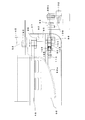
- FIGS. 6 and 7 illustrate an operation lever for opening and closing and locking the lid
- FIG. 8 illustrates a guide plate of the operation lever.
- One end portion 88a of the operation lever 88 is fixed to the curved portion of the lid main body 50 by welding or the like, and the operator operates by grasping the other end portion 88b.
- the other end portion 88b of the operation lever 88 is disposed so as to protrude from the lid body exterior 37, but the one end portion 88a is disposed in the lid body exterior 37 so as not to be seen from the outside. .
- the operation lever 88 is provided so as to be movable along the long hole 94 of the guide plate 92 fixed to the support plate 48.
- the guide plate 92 includes an arc-shaped main body 95 having the same radius of curvature as the operation locus of the operation lever 88 and a fixing portion 96 that is a member fixed to the support plate 48.
- a long hole 94 is formed in the arcuate main body 95 of the guide plate 92 along the moving direction of the operation lever 88, and a middle portion of the operation lever 88 enters into the long hole 94.
- a stopper 90 that restricts the operation of the operation lever 88 is provided in the middle of the operation lever 88 in the longitudinal direction.
- the stopper 90 includes a pin 98 provided on the operation lever 88 and a semicircular storage recess 100 in which the pin 98 is stored.
- the pin 98 is housed in the housing recess 100 formed in the arcuate body 95 of the guide plate 92, thereby restricting the operation of the operation lever 88.
- the pin 98 is attached to a slide lock bar 104 provided on the operation lever 88.
- the slide lock bar 104 is housed in a slide groove 101 formed along the longitudinal direction of the operation lever 88 so as to be slidable along the longitudinal direction of the operation lever 88. In the slide lock bar 104 in the slide groove 101, the pin 98 is constantly urged toward the guide plate 92 by an urging means 106 such as a spring.
- a slide guide cover 105 is attached to both the front and back surfaces of the operation lever 88 so as to cover the front and back surfaces of the slide lock bar 104 in order to prevent the slide lock bar 104 from coming off from the slide groove 101. ing.
- Each slide guide cover 105 is formed with a semicircular restriction recess 109 for restricting the operation of the pin 98 in the direction opposite to the urging direction.
- the stopper 90 is released by a stopper release button 102 provided on the other end 88b side of the operation lever 88.
- the stopper release button 102 is arranged so as to protrude to the other end side of the other end portion 88b of the operation lever 88, and when the operator holds the operation lever 88 with one hand, The stopper release button 102 can be operated with such a finger.
- the stopper release button 102 is connected to the slide lock bar 104 via a connecting member 108.
- the slide lock bar 104 slides in the slide groove 101 toward the one end portion 88 a of the operation lever 88 against the urging force of the urging means 106 via the connecting member 108. Moving.
- the slide lock bar 104 moves in the direction of the one end portion 88 a, the pin 98 comes out of the housing recess 100, and the operation lever 88 can move in the long hole 95 of the guide plate 92.
- the storage recess 100 of the stopper 90 is formed at two predetermined locations on the guide plate 92. This is because the claw portion 52 of the lid body 36 is engaged with the claw portion 46 of the can body 34 (the position where the claw portion 52 is locked and cannot be opened and closed), and the claw portion 52 of the lid body 36 is connected to the claw portion 46 of the can body 34. Are two positions that are not meshed with each other (positions that can be opened and closed when the lock is released). For example, if the storage recess 100 formed at the upper position is set to the unlocking position and the storage recess 100 formed at the lower position is set to the lock position, the operator can actually operate the nail by operating the operation lever 88 during this period. The lid 36 can be easily opened and closed without visually confirming the positional relationship between the portions 46 and 52.
- This position is a position where the claw part 52 of the lid body 50 is completely displaced from the claw part 46 of the can body 34 and the lock is released, and when the operator pulls the operation lever 88 toward this side at this position, the hinge part.
- the shaft rotates and the lid 36 opens.
- the operation lever 88 is configured such that two members are connected by a connecting pin 110 in the middle part. With this configuration, even when one end portion 88a of the operation lever 88 is fixed to the lid body 36 by welding, the operation lever 88 can be accurately inserted into the elongated hole 94 of the guide plate 92. That is, even if a slight error occurs in the directionality of the operation lever 88 due to thermal deformation during welding of the one end portion 88a, this error can be corrected at the connection location by the connection pin 110. The entry into the hole 94 is made accurately.
Landscapes
- Engineering & Computer Science (AREA)
- General Engineering & Computer Science (AREA)
- Mechanical Engineering (AREA)
- Closures For Containers (AREA)
- Pressure Vessels And Lids Thereof (AREA)
Abstract
L'invention concerne un récipient sous pression qui, sans être un fardeau pour un opérateur, permet l'ouverture et la fermeture d'un couvercle et le verrouillage du couvercle et d'un contenant, chacune de ces opérations pouvant être effectuée d'une seule main. Le récipient sous pression comporte : un contenant (34) dans lequel une ouverture (35) est formée ; un couvercle (36) qui ferme l'ouverture (35) ; et une charnière (42) pour l'ouverture et la fermeture du couvercle (36). Plusieurs griffes (46) faisant saillie vers l'intérieur sont disposées sur le bord de l'ouverture du contenant (34). Le couvercle (36) comporte : un corps principal de couvercle (50) sur lequel plusieurs griffes (52) faisant saillie vers l'extérieur sont disposées ; et une plaque de support (48) qui est réunie à la charnière (42) et qui supporte le corps principal de couvercle (50) en rotation avec le centre du corps principal de couvercle comme ligne axiale. Un levier de fonctionnement (88) est prévu, dont une extrémité (88a) est fixée au corps principal de couvercle (50) et l'autre extrémité (88b) est formée en tant que section de prise qu'un opérateur attrape. Le levier de fonctionnement (88) est disposé parallèlement au plan de l'ouverture (35) du contenant (34) et peut être actionné par le déplacement de l'autre extrémité (88b) vers le haut et vers le bas d'une manière telle que le corps principal de couvercle (50) tourne avec le centre du corps principal de couvercle comme ligne axiale.
Priority Applications (1)
| Application Number | Priority Date | Filing Date | Title |
|---|---|---|---|
| JP2013502144A JPWO2012117606A1 (ja) | 2011-03-01 | 2011-10-17 | 圧力容器 |
Applications Claiming Priority (2)
| Application Number | Priority Date | Filing Date | Title |
|---|---|---|---|
| JP2011-043888 | 2011-03-01 | ||
| JP2011043888 | 2011-03-01 |
Publications (1)
| Publication Number | Publication Date |
|---|---|
| WO2012117606A1 true WO2012117606A1 (fr) | 2012-09-07 |
Family
ID=46757556
Family Applications (1)
| Application Number | Title | Priority Date | Filing Date |
|---|---|---|---|
| PCT/JP2011/073867 Ceased WO2012117606A1 (fr) | 2011-03-01 | 2011-10-17 | Recipient sous pression |
Country Status (2)
| Country | Link |
|---|---|
| JP (1) | JPWO2012117606A1 (fr) |
| WO (1) | WO2012117606A1 (fr) |
Cited By (1)
| Publication number | Priority date | Publication date | Assignee | Title |
|---|---|---|---|---|
| CN109809058A (zh) * | 2019-03-25 | 2019-05-28 | 宁夏合力万兴汽车制造有限公司 | 带盖密封罐及载有带盖密封罐的特种车辆 |
Citations (5)
| Publication number | Priority date | Publication date | Assignee | Title |
|---|---|---|---|---|
| JPS4319451Y1 (fr) * | 1964-07-30 | 1968-08-14 | ||
| JPS5853998U (ja) * | 1981-10-09 | 1983-04-12 | 株式会社神戸製鋼所 | 圧力容器の覗き窓構造 |
| JPS6425801U (fr) * | 1987-08-06 | 1989-02-14 | ||
| JPH01154024U (fr) * | 1988-04-18 | 1989-10-24 | ||
| JP2005069374A (ja) * | 2003-08-25 | 2005-03-17 | Nof Corp | 耐圧収容容器 |
-
2011
- 2011-10-17 JP JP2013502144A patent/JPWO2012117606A1/ja active Pending
- 2011-10-17 WO PCT/JP2011/073867 patent/WO2012117606A1/fr not_active Ceased
Patent Citations (5)
| Publication number | Priority date | Publication date | Assignee | Title |
|---|---|---|---|---|
| JPS4319451Y1 (fr) * | 1964-07-30 | 1968-08-14 | ||
| JPS5853998U (ja) * | 1981-10-09 | 1983-04-12 | 株式会社神戸製鋼所 | 圧力容器の覗き窓構造 |
| JPS6425801U (fr) * | 1987-08-06 | 1989-02-14 | ||
| JPH01154024U (fr) * | 1988-04-18 | 1989-10-24 | ||
| JP2005069374A (ja) * | 2003-08-25 | 2005-03-17 | Nof Corp | 耐圧収容容器 |
Cited By (1)
| Publication number | Priority date | Publication date | Assignee | Title |
|---|---|---|---|---|
| CN109809058A (zh) * | 2019-03-25 | 2019-05-28 | 宁夏合力万兴汽车制造有限公司 | 带盖密封罐及载有带盖密封罐的特种车辆 |
Also Published As
| Publication number | Publication date |
|---|---|
| JPWO2012117606A1 (ja) | 2014-07-07 |
Similar Documents
| Publication | Publication Date | Title |
|---|---|---|
| JP5505644B2 (ja) | ロック装置 | |
| JP2014510857A (ja) | 自動車用ドア及びパネルの位置調整要素 | |
| US20180274265A1 (en) | Rotary locking device | |
| US20220134874A1 (en) | Lid opening and closing device | |
| US9855863B2 (en) | Lock device | |
| WO2013099601A1 (fr) | Dispositif de verrouillage pour corps d'ouverture/de fermeture | |
| JP5986023B2 (ja) | バレル研磨装置 | |
| CN107521419B (zh) | 用于车辆的后门闩锁设备 | |
| JP5494964B2 (ja) | ロック装置の固定構造 | |
| WO2012117606A1 (fr) | Recipient sous pression | |
| US7591387B2 (en) | Fuel filling port structure of a fuel tank | |
| JP5865343B2 (ja) | 圧力容器 | |
| US9016515B2 (en) | Removable gripping device for a cooking vessel without indexing | |
| US10343823B2 (en) | Cover for closing a box and assembly comprising a box and a cover of said type | |
| US12590478B2 (en) | Lid opening/closing structure | |
| JP6275176B2 (ja) | パーキング解除ユニット | |
| US9764591B2 (en) | Cover with a seal for closing a can, and assembly comprising a can and such a cover | |
| JP2008261129A (ja) | 自動車用ドアハンドル装置 | |
| JP7701294B2 (ja) | ロック装置 | |
| KR101902232B1 (ko) | 밸브 셔터의 멀티 핸들 | |
| JP2006118115A (ja) | 二段階開放型密閉リフトハンドル装置 | |
| JP2007327272A (ja) | 施錠装置用補助錠 | |
| JP4739775B2 (ja) | ルーフロック装置 | |
| JP6503576B2 (ja) | ラッチ装置 | |
| JP2020037792A (ja) | 車両用リッドロック機構、車両用リッドロック装置、及び車両用ロック機構 |
Legal Events
| Date | Code | Title | Description |
|---|---|---|---|
| 121 | Ep: the epo has been informed by wipo that ep was designated in this application |
Ref document number: 11859848 Country of ref document: EP Kind code of ref document: A1 |
|
| ENP | Entry into the national phase |
Ref document number: 2013502144 Country of ref document: JP Kind code of ref document: A |
|
| NENP | Non-entry into the national phase |
Ref country code: DE |
|
| 122 | Ep: pct application non-entry in european phase |
Ref document number: 11859848 Country of ref document: EP Kind code of ref document: A1 |