WO2012117655A1 - Dispositif d'égalisation de forme d'onde - Google Patents
Dispositif d'égalisation de forme d'onde Download PDFInfo
- Publication number
- WO2012117655A1 WO2012117655A1 PCT/JP2012/000086 JP2012000086W WO2012117655A1 WO 2012117655 A1 WO2012117655 A1 WO 2012117655A1 JP 2012000086 W JP2012000086 W JP 2012000086W WO 2012117655 A1 WO2012117655 A1 WO 2012117655A1
- Authority
- WO
- WIPO (PCT)
- Prior art keywords
- value
- filter
- coefficient
- unit
- error
- Prior art date
- Legal status (The legal status is an assumption and is not a legal conclusion. Google has not performed a legal analysis and makes no representation as to the accuracy of the status listed.)
- Ceased
Links
Images




Classifications
-
- H—ELECTRICITY
- H04—ELECTRIC COMMUNICATION TECHNIQUE
- H04L—TRANSMISSION OF DIGITAL INFORMATION, e.g. TELEGRAPHIC COMMUNICATION
- H04L25/00—Baseband systems
- H04L25/02—Details ; arrangements for supplying electrical power along data transmission lines
- H04L25/03—Shaping networks in transmitter or receiver, e.g. adaptive shaping networks
- H04L25/03006—Arrangements for removing intersymbol interference
- H04L25/03012—Arrangements for removing intersymbol interference operating in the time domain
- H04L25/03019—Arrangements for removing intersymbol interference operating in the time domain adaptive, i.e. capable of adjustment during data reception
-
- H—ELECTRICITY
- H04—ELECTRIC COMMUNICATION TECHNIQUE
- H04L—TRANSMISSION OF DIGITAL INFORMATION, e.g. TELEGRAPHIC COMMUNICATION
- H04L25/00—Baseband systems
- H04L25/02—Details ; arrangements for supplying electrical power along data transmission lines
- H04L25/03—Shaping networks in transmitter or receiver, e.g. adaptive shaping networks
- H04L25/03006—Arrangements for removing intersymbol interference
- H04L2025/03592—Adaptation methods
- H04L2025/03598—Algorithms
- H04L2025/03681—Control of adaptation
- H04L2025/03687—Control of adaptation of step size
-
- H—ELECTRICITY
- H04—ELECTRIC COMMUNICATION TECHNIQUE
- H04L—TRANSMISSION OF DIGITAL INFORMATION, e.g. TELEGRAPHIC COMMUNICATION
- H04L25/00—Baseband systems
- H04L25/02—Details ; arrangements for supplying electrical power along data transmission lines
- H04L25/03—Shaping networks in transmitter or receiver, e.g. adaptive shaping networks
- H04L25/03006—Arrangements for removing intersymbol interference
- H04L2025/03592—Adaptation methods
- H04L2025/03598—Algorithms
- H04L2025/03681—Control of adaptation
- H04L2025/037—Detection of convergence state
Definitions
- the present invention relates to a waveform equalizer that updates filter coefficient values.
- a waveform equalizer (waveform, etc.) is used to suppress a reflected wave generated in a transmission path etc. and a plurality of scattered reflected waves. Chemical) is used.
- the filter tap coefficients of the waveform equalizer are designed to be adaptively processed in order to cope with reflected waves with different delay amounts generated under various environments and reflected waves that fluctuate with time.
- filter tap coefficients to be adaptively processed are calculated from an error which is a difference between a filter output and a value to be expected, and are automatically determined so as to reduce the value of the error.
- a coefficient update algorithm that determines filter tap coefficients from error detection greatly affects the convergence time and accuracy of waveform equalization that suppresses reflected waves. Also, the number of filter taps determines the adaptive equalization range, the update period of the filter tap coefficients determines the removal level of the time-varying reflected wave, and both greatly affect the waveform equalization performance. Do.
- FIG. 3 shows a conventional waveform equalizer described in Patent Document 1 mentioned above.
- the filter unit 1100 multiplies the input signal by the filter tap coefficient value.
- the error detection unit 1200 detects an error by calculating the comparison result between the output of the filter unit 1100 and the value to be expected.
- the delay unit 1420 adjusts the timing of generating filter tap coefficients from the input signal.
- the coefficient generator A 1411 and the coefficient generator B 1412 generate coefficients by different algorithms, and calculate filter tap coefficient values from the error signal whose error is detected and the input signal passed through the delay unit 1420.
- the error control unit 1300 compares the threshold value prepared in advance with the error signal, and switches to one of the coefficient generator A 1411 and the coefficient generator B 1412 based on the comparison result to determine the filter tap coefficient value. doing.
- the filter coefficient value is calculated for each sampling, and the filter coefficient values of all the filters are updated.
- the calculation may be performed even when the necessity of the update is actually low (for example, when the filter coefficient value hardly changes before and after the update), which increases the amount of calculation and wastes power consumption. I am invited.
- the present invention has been made under such problems, and it is an object of the present invention to provide a waveform equalizer that contributes to reduction of the amount of calculation and suppression of power consumption when updating filter coefficient values. Do.
- a waveform equalizer is a waveform equalizer that reduces transmission distortion of an input signal used for broadcasting, and is subjected to filter processing using filter coefficient values and input. Comparing a filter unit having a plurality of sub-filters for updating the filter coefficient value using a value, an output from the filter unit, and an expected value expected as a result of filtering the input signal Error detection unit for detecting an error and outputting it as an error signal, and a coefficient updating unit for generating a value used for updating a filter coefficient value from the error signal and the input signal and outputting the value to the filter unit; A threshold value is held, the threshold value is compared with the filter coefficient value of the sub filter, and if the filter coefficient value is smaller, the filter updating unit It characterized in that it comprises a error controller for instructing so that new is not performed.
- the waveform equalizer of the present invention it is possible to contribute to reduction of the operation amount and suppression of power consumption when updating the filter coefficient value.
- a block diagram showing a basic configuration of a waveform equalization device according to Embodiments 1 to 3 of the present invention Block diagram showing the configuration of the waveform equalizer in the first embodiment according to the present invention
- Block diagram showing the configuration of a conventional waveform equalizer Block diagram showing the configuration of the waveform equalizer in the second embodiment according to the present invention
- Flow chart showing coefficient update control in Embodiment 2 according to the present invention Diagram showing an example of configuration of FIR filter Block diagram showing the configuration of the waveform equalizer in the first embodiment in the third embodiment according to the present invention
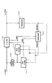
- FIG. 1 is a block diagram showing a basic configuration of a waveform equalizer in the first to third embodiments of the present invention.
- the filter unit 100 receives an input signal used for broadcast waves and the like.
- the filter unit 100 has a plurality of sub-filters, and in each sub-filter, an input signal is multiplied by a filter tap coefficient value, and an output result of each sub-filter is added to obtain the final result of the waveform equalizer. Output as a signal.
- a signal of the Advanced Television Systems Committee (ATSC) standard can be mentioned.
- the error detection unit 200 detects an error based on the comparison result of the output of the filter unit 100 and the value to be expected, and outputs an error signal indicating an error value.
- the coefficient updating unit 400 generates a value used for updating the filter coefficient value (hereinafter may be referred to as “updated difference value”) from the input signal and the error value indicated by the error signal, and filters the updated difference value. Output to section 100.
- updated difference value a value used for updating the filter coefficient value (hereinafter may be referred to as “updated difference value”) from the input signal and the error value indicated by the error signal, and filters the updated difference value.
- the error control unit 300 (301) adjusts the coefficient update period from the filter tap coefficient value and the error value (used as necessary) indicated by the error signal.
- the error control unit 300 holds the threshold value, compares the threshold value with the filter coefficient value of the sub filter, and for example, when the filter coefficient value is smaller, the filter to the coefficient updating unit 400 Give an instruction to prevent updating of coefficient values.
- the error control unit 300 does not necessarily use the error value, and is used in the second embodiment described later, but is not used in the first and third embodiments.
- the filter tap coefficient value calculated at the time of correction is smaller than a predetermined threshold value for an input signal including a reflection that can be sufficiently received without correction by such a configuration.
- the coefficient updating can be stopped so that the waveform equalizer does not perform unnecessary arithmetic processing.
- the reception limit is in an environment where reflected waves of a strong electric field exist
- an environment where only reflected waves of weak electric fields exist such as an easily receivable environment, etc.
- the plurality of sub-filters are formed by connecting three or more sub-filters in series, and the error control unit has an adder for adding filter coefficient values of two or more sub-filter groups, and the error The control unit compares the added filter coefficient value with the threshold value, and if the added filter coefficient value is smaller, the filter of the sub filter group with respect to the coefficient updating unit is used as the instruction. It may be configured to issue an instruction to prevent the coefficient value from being updated.
- N is an integer of 2 or more sub-filters are connected in series, and the coefficient updating unit individually separates values used for updating filter coefficient values of the N sub-filters.
- the error control unit has N threshold values respectively corresponding to the filter coefficient values of the respective subfilters, compares each filter coefficient value with the corresponding threshold value, and An instruction for preventing the updating of the filter coefficient value of the subfilter corresponding to the smaller one may be performed as the instruction.
- the instruction may be configured to include a period indicating stop of updating.
- the instruction may be configured to include an effect of setting the update cycle to a fixed interval.
- the amount of operation of the waveform equalizer can be reduced.
- the error control unit includes a counter that counts the number of instructions.
- the counter may stop the comparison operation between the filter coefficient value and the threshold until the count value reaches the preset value, and the error control unit may issue the instruction while the comparison is stopped. Absent.
- the error control unit calculates the amount of change from the difference between the filter coefficient value input from the filter unit last time and the filter coefficient value newly input from the filter unit, and if the calculated change amount is equal to or less than a predetermined value, The count value may be reset.
- the comparison operation can be postponed by resetting the count value, which can contribute to the reduction of the amount of calculation.
- the error control unit calculates the amount of change from the difference between the filter coefficient value input from the filter unit last time and the filter coefficient value newly input from the filter unit, and the calculated change amount is larger than a predetermined value.
- the instruction to the coefficient update unit may be suppressed.
- the error control unit may suppress the instruction to the coefficient update unit if the error indicated by the error signal output from the error detection unit is equal to or greater than a predetermined value.
- coefficient updating can be performed when the error is large.
- the error control unit may stop the comparison until a predetermined time has elapsed since the previous comparison, and may issue the instruction although the comparison is not performed.
- a waveform equalizer is a waveform equalizer that reduces transmission distortion of an input signal used for broadcasting, and performs filter processing using a filter coefficient value and uses the input value.
- An error is detected by comparing a filter unit having a plurality of sub-filters for updating filter coefficient values, an output from the filter unit, and an expected value expected as a result of filtering the input signal.
- An error detection unit that outputs an error signal, a coefficient update unit that generates a value used for updating a filter coefficient value from the error signal and the input signal, and outputs the value to the filter unit; Compare the calculated filter coefficient value with the filter coefficient value newly input from the filter unit to calculate the change amount from the difference, and if the calculated change amount is equal to or less than the threshold value, Characterized in that it comprises a error controller for instructing so that updating of the filter coefficient values is not performed for the number updating unit.
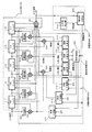
- FIG. 2 is a block diagram showing the configuration of the waveform equalizer in the first embodiment.
- the same components as in FIG. 1 will be assigned the same reference numerals and descriptions thereof will be omitted.
- the filter unit 100 includes FIR filters 111 to 115 which are five filter taps obtained by weighting an input signal with filter tap coefficient values, and an adder 120 which integrates the outputs of the filter taps and outputs the result as an output signal of the waveform equalizer. It is composed of
- the FIR filter is a Finite Impulse Response filter, which is one of the types of digital filters.
- an FIR filter is used as an example of a digital filter that performs adaptive processing, a function of holding filter tap coefficient values, and a function of multiplying the held filter tap coefficient values and the input signal and outputting the result. It has a function of outputting an input signal to a filter at a later stage, and a function of updating a filter tap coefficient value (sometimes referred to as a "filter coefficient value").
- FIG. 1 A configuration example of the FIR filter 111 is shown in FIG.
- the FIR filter 111 includes a delay unit 111a, an adder 111b, a delay unit 111c, and a multiplier 111d.
- the adder 111 b adds the previous filter coefficient value C n output from the delay unit 111 c and ⁇ EX n (updated difference value) output from the multiplier 431 to obtain a new filter coefficient value C n. Output +1 .
- Such updating of filter coefficient values will be described later.
- the error detection unit 200 includes an expected value detector 210 and an expected value comparator 220.
- the expected value detector 210 derives an expected value signal predicted from the output signal of the adder 120.
- the expected value comparator 220 outputs an error signal indicating an error value which is a difference between the output signal of the waveform equalizer and the expected value signal.
- the coefficient updating unit 400 includes a coefficient generator A 411, a coefficient generator B 412, a coefficient generator C 413, five multipliers 431 to 435, and five delay devices 421 to 425.
- the coefficient update unit 400 will be described.
- the coefficient generator A 411 receives an error signal (indicating an error value E) from the error detection unit 200, zero that may be used as the error value E, and a control signal from the error control unit 300. Also, the value ( ⁇ ) of the step gain is held.
- the coefficient generator A 411 outputs a value obtained by multiplying the value of the step gain by the error value.
- the error value either the error value indicated by the error signal as it is or zero is used based on the instruction content of the control signal.
- the coefficient generator B412 and the coefficient generator C413 are also similar to this.
- the multipliers 431 to 435 output updated differential values of the filter tap coefficient values of the filter taps.
- the delay units 421 to 425 adjust the multiplication timing of the output of the coefficient generator and the input signal for each filter tap.
- the error control unit 300 includes a coefficient comparator A 311, a coefficient comparator B 312, a coefficient comparator C 313, an update controller 320, an adder 331, and an adder 332.
- the coefficient comparator A 311, the coefficient comparator B 312, and the coefficient comparator C 313 compare magnitudes between the filter tap coefficient value of each filter tap of the filter unit 100 or the sum of the filter tap coefficient values and a predetermined threshold value. Is a comparator that outputs the result.
- the update controller 320 controls the update periods of the coefficient generator A411, the coefficient generator B412, and the coefficient generator C413 based on the comparison results of the coefficient comparator A311, the coefficient comparator B312, and the coefficient comparator C313.
- the adder 331 outputs the sum of the filter tap coefficient values of the FIR filters 111 and 112, and the adder 332 outputs the sum of the filter tap coefficient values of the FIR filters 114 and 115.
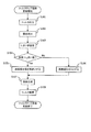
- FIG. 5 is a diagram showing a coefficient update control flow of the waveform equalizer.
- the input signal which is a signal input to the waveform equalizer is output by the process of the filter unit 100 (S101).
- the output signal of the waveform equalizer is also output to the error detection unit 200, and the error detection unit 200 performs error detection processing and outputs an error signal indicating an error value (S102).
- the error control unit 300 sets a threshold value to be compared with the filter tap coefficient value (S103), and compares the filter tap coefficient value of the filter unit 100 with the threshold value (S104).
- the error control unit 300 determines that the error value detected in S102 is treated as an error (S105). If the filter tap coefficient value is equal to or less than the threshold (S104: No), the error control unit 300 sets the error to zero in order to stop the coefficient update (S106).
- the coefficient updating unit 400 generates an updated value of the filter tap coefficient from the results of S105 and S106 (S107).
- the coefficient update unit 400 When the process goes through S105, the coefficient update unit 400 generates an update value using the error value indicated by the error signal received from the error detection unit 200, multiplies the generated update value with the input signal, and generates an update difference value. Is output (S108).
- the filter unit 100 updates the filter tap coefficient value using the updated difference value output from the coefficient updating unit 400.
- the error control unit 300 transmits a control signal instructing the coefficient updating unit 400 to set the error value to zero.
- the initial state of the filter tap coefficient value of the FIR filter is that only the FIR filter 113 called a center tap filter has a value of 1, and the other FIR filters 111, 112, 114, and 115 have zero.
- the input signal of the waveform equalizer is input as it is to the first stage filter FIR filter 111.
- the filter tap coefficient value of the initial value is zero
- the multiplication result of the FIR filter 111 and the filter tap coefficient value is zero
- the output is output to adder 120.
- the input signal at the time of the previous operation is outputted from the FIR filter 111 and becomes the input signal of the FIR filter 112 as it is. Also, an input signal of the waveform equalizer is newly input, and becomes an input of the FIR filter 111.
- the FIR filter 112 outputs a value obtained by multiplying the input signal and the filter tap coefficient value to the adder 120, and outputs the input signal to the FIR filter 113 in the next operation.
- the input signal of the waveform equalizer delays the operation of the FIR filter 111, the FIR filter 112, and the FIR filter 113, and becomes an output signal of the waveform equalizer.
- the filter tap coefficient value of the filter unit 100 By changing the filter tap coefficient value of the filter unit 100, it is possible to freely change the input signal and use it as the output signal of the waveform equalizer. That is, by setting the filter tap coefficient value to an appropriate value, the filter unit 100 can correct and output the input signal of the waveform equalizer.
- the filter tap coefficient value can be changed by the update difference value of the filter tap coefficient value output by the coefficient updating unit 400, and the coefficient updating unit 400 generates the filter tap coefficient value from the error signal by the control signal from the error control unit 300.
- the error signal is generated by the error detection unit 200, but the input signal of the error detection unit 200 is the output signal of the waveform equalizer itself.
- the expected value detector 210 has a function of estimating the correct value of the input signal of the waveform equalizer, and the expected value comparator 220 has a function of comparing the output of the waveform equalizer with its expected value. Have.
- the expected value detector 210 Since the value of the input signal of the waveform equalizer different from the original accurate signal is corrected by the filter unit 100 due to the generation of the reflected wave due to the reflection of the transmission path etc., the expected value detector 210 prepares in advance. Is compared to the current value. Then, the expected value detector 210 derives the correct signal value and the most expected value. Then, the expected value comparator 220 compares the expected value derived by the expected value detector 210 with the value of the output signal of the waveform equalizer, and outputs the difference value as an error value.
- the original accurate signal pattern can be expressed as 4 of “0
- the expected value comparator 220 outputs the expected value pattern “1
- the coefficient generator A 411, the coefficient generator B 412, and the coefficient generator C 413 multiply the error signal input to the coefficient update unit 400 by the step gain and output the result, and the control signal of the error control unit 300 It is possible to change the magnitude of the value and the value of the multiplication output itself.
- the delay units 421 to 425 are necessary for delaying the input signal of digital processing so that the coefficient update differential value can be generated and updated from the input signal before updating the filter tap coefficient value of each of the FIR filters 111 to 115. is there.
- multipliers 431 to 435 are required to multiply the outputs of coefficient generator A 411, coefficient generator B 412, and coefficient generator C 413 and output coefficient update difference values of FIR filters 111 to 115, respectively.
- the coefficient updating method is performed by the LMS algorithm, the coefficient value C n + 1 updated by digital processing is shown in (Expression 1).
- C n + 1 C n + ⁇ EX n (Equation 1)
- C n is a current coefficient value
- ⁇ is a step gain
- E is an error value (error signal)
- X n is a current input signal.
- the LMS algorithm is a Least Mean Square algorithm, which performs coefficient updating while reducing the error value by multiplying the error value indicated by the error signal, the step gain, and the input signal.
- the LMS algorithm is described as an example.
- the present invention is not limited to this, and various methods that improve the LMS algorithm, a recursive least square algorithm (RLS) algorithm, and the like may be adopted.
- RLS recursive least square algorithm
- the coefficient generator B 412 performs coefficient update on the FIR filter 113 which is a center tap filter. Also, the coefficient generator A 411 performs the coefficient update of the FIR filter 111 and the FIR filter 112 of the previous stage. Furthermore, the coefficient generator C413 performs the updating of the coefficients of the FIR filter 114 and the FIR filter 115 in the latter stage.
- the amount of delay of the fluctuating reflected wave becomes small and is corrected almost by the FIR filter 113 which is a center tap, and the coefficient generator B 412 performs coefficient updating so as to follow the fluctuation of reflection.
- the reflected wave which hardly fluctuates is corrected by the FIR filter 114 or the FIR filter 115 because the delay amount is large, and the coefficient generator C 413 suppresses the coefficient update.
- the filter tap coefficient value for correction can be changed to a pinpoint by performing the coefficient update on the reflected wave of the specific delay amount included in the input signal, so the error signal is reduced by the correction. It is possible to shorten the convergence time required to improve the performance of the waveform equalizer.
- the coefficient comparator A 311 is involved in the coefficient update of the coefficient generator A 411 and reads the filter tap coefficient values of the FIR filter 111 and the FIR filter 112 as a judgment index of the coefficient update.
- the coefficient comparator B312 is involved in the coefficient updating of the coefficient generator B412 and reads the filter tap coefficient value of the FIR filter 113
- the coefficient comparator C313 is involved in the coefficient updating of the coefficient generator C413 and the FIR filter 114 and FIR
- the filter tap coefficient value of the filter 115 is read.
- the coefficient comparator A 311, the coefficient comparator B 312, and the coefficient comparator C 313 can take different threshold values, and can compare each read filter tap coefficient value with the threshold value. In the comparison process, if the filter tap coefficient value exceeds the threshold value, 1 (indicating that the operation of updating the coefficient is performed) is output, and if the filter tap coefficient value is a value equal to or less than the threshold value. Output 0 (do not perform the coefficient update operation).
- the update controller 320 generates the coefficient generator A411 and the coefficient generator B412 based on the comparison results of the coefficient comparator A311, the comparison results of the coefficient comparator B312, and the comparison results of the coefficient comparator C313, respectively. It is possible to output a control signal that controls the behavior of the coefficient update of the coefficient generator C413.
- the coefficient comparator A 311 reads a coefficient value A as a result of adding the filter tap coefficient values of the FIR filter 111 and the FIR filter 112 by the adder 331. By doing this, the amount of coefficient comparison processing can be halved compared to comparing the filter tap coefficient values of the respective FIR filters.
- the coefficient comparator C 313 also reads the coefficient value C as a result of adding the filter tap coefficient values of the FIR filter 114 and the FIR filter 115 by the adder 332.
- the coefficient comparator needs to be increased by the number of FIR filters.
- the increase in coefficient comparators is an increase in comparison processing of filter tap coefficient values, resulting in a huge amount of calculation.
- the threshold A of the coefficient comparator A 311 is 0.3
- the threshold B of the coefficient comparator B 312 is 0.1
- the threshold C of the coefficient comparator C 313 is 0.4.
- the filter tap coefficient value of the FIR filter 111 is “0.2
- the filter tap coefficient value of the FIR filter 112 is “0.2
- the filter tap coefficient value of the FIR filter 113 is“ 0.9
- the filter tap coefficient value of the FIR filter 114 is“ 0.2
- the adder 331 sequentially outputs “0.4
- the adder 332 sequentially outputs “0.2
- the coefficient B is the filter tap coefficient value of the FIR filter 113 as it is, and is in the order of “0.9
- the coefficient comparator A 311 compares the coefficient A (0.4
- the coefficient comparator B312 compares the coefficient B (0.9
- the coefficient comparator C313 compares the coefficient C (0.2
- the update controller 320 causes the output to the coefficient generator A to be output as 0 when the output of the coefficient comparator A 311 is 0, the filter tap coefficient values of the FIR filter 111 and the FIR filter 112 are one of four times. It becomes the operation of the coefficient update of time. Similarly, the filter tap coefficient values of the FIR filter 114 and the FIR filter 115, which are updated by the output of the coefficient generator C313, become the operation of updating the coefficients twice out of four times.
- the filter tap coefficient value of the FIR filter 113 which is updated by the output of the coefficient generator B 312 is an operation of updating the coefficients four times out of four times and constantly.
- the error control unit 300 compares the filter tap coefficient value of the filter unit 100 with the threshold value with the three coefficient comparators, and stops the coefficient updating unit 400 from updating the coefficient when the value is less than the threshold value.
- the update difference value of the coefficient update unit 400 is zero by transmitting the control signal as described above, the coefficient update is stopped, and the amount of calculation due to the filter tap coefficient update can be reduced.
- the error value indicated by the error signal may be defined to be 1 as an instruction to stop the coefficient updating.
- the FIR filter is provided as the filter tap of the filter unit 100 in the first embodiment, another filter such as an IIR (Infinite Impulse Response) filter may be used.
- IIR Infinite Impulse Response
- the convergence time of the filter tap coefficient value and the variation amount of the coefficient value differ, but the same effect can be obtained by appropriately setting the threshold value.
- five FIR filters of filter unit 100 three coefficient comparators of error control unit 300, two adders, three coefficient generators of coefficient updating unit 400, and a delayer
- five and five multipliers are shown, the number is not particularly limited. When the number is increased, it is considered that the waveform equalization performance is improved because the accuracy of digital processing generally improves.
- the coefficient update is stopped by setting the update difference value of the coefficient update unit 400 to zero.
- the method is not limited to this as long as the coefficient update in the filter unit 100 can be stopped.
- the error control unit 300 may send a control signal indicating that the update difference value of the coefficient updating unit 400 is an invalid value to the coefficient updating unit 400.
- FIG. 4 is a block diagram showing the configuration of a waveform equalization apparatus according to a second embodiment of the present invention.
- FIG. 4 the same components as in FIG. 1 and FIG.
- the error control unit 301 includes a delay unit 340, a coefficient variation detector 350, a coefficient comparator 310, an update controller 320, and a counter 360.
- the delay 340 adjusts the timing to compare the filter tap coefficient value of the filter unit 100 with the previous value.
- the coefficient variation detector 350 detects the coefficient variation value by comparing the filter tap coefficient value of the filter unit 100 with the filter tap coefficient value output from the delay unit 340 and outputting the difference.
- the coefficient comparator 310 outputs the result of comparing the coefficient fluctuation value detected by the coefficient fluctuation detector 350 with a predetermined threshold value.
- the update controller 320 outputs a control signal for controlling the update cycle of the coefficient update unit 400 based on the comparison result by the coefficient comparator 310 and the error signal from the error detection unit 200.
- the counter 360 detects a control signal from the update controller 320 to the coefficient update unit 400, and counts the number of times. When the count value reaches the preset value, a stop signal indicating stop of operation is sent to the coefficient comparator 310 and the coefficient variation detector 350 to stop these operations.
- FIG. 6 is a diagram showing a coefficient update control flow of the waveform equalizer.
- the signal input to the waveform equalizer is processed by the filter unit 100 and output as an output signal (S201).
- the output signal of the waveform equalizer is also output to the error detection unit 200, and the error detection unit 200 performs error detection processing to output an error signal indicating an error value (E) (S202).
- the update controller 320 compares whether the error value (E) indicated in the error signal received from the error detection unit 200 is 0.5 or more (S203).
- the coefficient variation detector 350 calculates the coefficient change amount from the difference between the current filter tap coefficient value and the previous filter tap coefficient value (S204).
- the coefficient comparator 310 sets a threshold for comparison with the calculated coefficient variation (S205), and the counter 360 sets a preset value (S206).
- S205 the calculated coefficient variation
- S206 a preset value
- the preset value is eight times. Note that these settings can be made, for example, by receiving an input from the user. When the setting has been made, S205 and S206 may be skipped.
- the update controller 320 confirms whether the set count value is eight times or more of the preset value (S207), and compares the coefficient variation with the threshold value in the case of eight or more times (S209).
- the counter 360 transmits a stop signal indicating stop of operation to the coefficient variation detector 350 and the coefficient comparator 310 to stop their operation (S208).
- the update controller 320 When S208 or S210 is followed, the update controller 320 outputs a control signal instructing the coefficient update unit 400 to make the error (E) zero in order to stop the coefficient update (S212).
- the value to be compared with the error value (E) in S203 may be set to a value other than 0.5.
- the coefficient updating unit 400 generates an updated value of the filter tap coefficient from the result of S211 or S212 (S214).
- the coefficient update unit 400 multiplies the generated update value with the input signal to output an update difference value (S215).
- the filter unit 100 updates the filter tap coefficient value using the updated difference value output from the coefficient updating unit 400.
- the coefficient variation detector 350 reads filter tap coefficient values before and after updating from the filter unit 100. Therefore, the coefficient variation detector 350 updates the filter tap coefficient value by the delay unit 340 and delays the processing for one process, and calculates the variation of the filter tap coefficient value before and after the update.
- the coefficient comparator 310 compares the coefficient change amount with the threshold value, and outputs 1 if the coefficient change amount exceeds the threshold value, and 0 if the coefficient change amount is less than the threshold value. Output
- the update controller 320 outputs a control signal of coefficient update to the counter 360 based on the comparison result of the coefficient comparator 310. However, the update controller 320 simultaneously reads the error signal from the error detection unit 200, and if the value of the error signal from the error detection unit 200 is 0.5 or more, it is for forcibly performing the coefficient update. The control signal is output to the counter 360.
- the counter 360 counts the number of control signals of the update controller 320. When the number is eight or more, the counter 360 outputs the control signal of the update controller 320 to the coefficient updating unit 400, and the number is less than eight. , And outputs a control signal for stopping coefficient updating to the coefficient updating unit 400. At this time, even if the number of counts of the counter 360 is less than eight, if the control signal for forcing the coefficient update to be output is output from the update controller 320, the number of counts is equal to eight or more. A control signal for operation is output to coefficient updating section 400.
- the threshold value of the coefficient comparator 310 is 0.1 and the filter tap coefficient value changes in the order of “0.9
- the coefficient fluctuation detector 350 sequentially outputs “0.2
- the coefficient comparator 310 sequentially outputs “1
- the update controller 320 reads the error signal from the error detection unit 200, and the error signal changes in the order of “0.3
- the coefficient is forcibly updated regardless of the value of the counter 360.
- the last fourth value is forcibly set to 1 regardless of the count number of the counter 360, “1
- the initial value is considered to be zero, and the counter 360 outputs “0
- the coefficient updating unit 400 when the control value from the counter 360 is zero, the update difference value is set to zero, and therefore the coefficient updating unit 400 operates as a coefficient updating cycle out of four times.
- the amount of change in the filter tap coefficient value of the filter unit 100 is compared with the threshold value in the error control unit 301 and is less than the threshold value, and the value of the error signal of the error detection unit 200 is small.
- a control signal to the coefficient updating unit 400 so as to stop the coefficient updating, and further counting the number of times of the control signal and transmitting the control signal so as to stop the coefficient updating also when the number is small.
- the update difference value of the coefficient update unit 400 By setting the update difference value of the coefficient update unit 400 to zero, the coefficient update is stopped, and the amount of calculation due to the filter tap coefficient update can be reduced.
- the filter tap coefficient value can be forcibly updated.
- the delay unit 340 is provided as means for calculating the change amount of the error control unit 301.
- a memory capable of storing or averaging values for a fixed period may be used. In this case, there is an advantage that the timing at which the change amount of the filter tap coefficient value is calculated and the change amount of the filter tap coefficient value are suppressed, and the comparison operation of the coefficient comparator 310 becomes easy.
- the counter set value of the counter 360 is eight times and the update effective value of the error signal of the update controller 320 is 0.2 or more, but the number is not particularly limited.
- the coefficient update period tends to be longer, and thus the power consumption can be reduced by reducing the amount of calculation in coefficient update, but the waveform equalization performance is degraded.
- the coefficient update period tends to be shorter, and the deterioration of the waveform equalization performance is suppressed, but it becomes difficult to suppress the power consumption due to the reduction of the calculation amount in the coefficient update.
- a plurality of sets may be stored as threshold values used for the coefficient comparator, and these may be selected and used.
- the error control units 300 and 301 can be configured according to the filter algorithm of the filter unit 100 and the filter configuration such as the coefficient value of each filter tap.
- the comparison operation is stopped using the count value, but instead of or in combination with this, the comparison operation may be stopped by timer control.
- timer control for example, instead of the determination of S207 of FIG. It can be realized by doing.
- the adders 331 and 332 for adding filter tap coefficient values are provided. However, in the third embodiment, such an adder is not provided. By providing a dedicated coefficient generator and coefficient comparator for each FIR filter, detailed control of updating of filter tap coefficient values is achieved.
- FIG. 8 is a block diagram showing the configuration of a waveform equalizer in the third embodiment.
- the same components as in FIG. 2 will be assigned the same reference numerals and descriptions thereof will be omitted.
- the filter unit 600 includes three FIR filters 111, 112 and 113.
- the filter tap coefficient value of the FIR filter 111 is input to the coefficient comparator A 311 of the error control unit 800, the filter tap coefficient value of the FIR filter 112 is input to the coefficient comparator B 312, and the coefficient comparator C 313 is input.
- the filter tap coefficient values of the FIR filter 113 are input.
- the coefficient generator A 411 of the coefficient update unit 900 generates an update value for the FIR filter 111
- the coefficient generator B 412 generates an update value for the FIR filter 112
- the coefficient generator C 413 generates an update value.
- the waveform equalizer according to the present invention can change the coefficient update period of the filter coefficient value according to the magnitude of the reflected wave, thereby reducing the amount of calculation when updating the filter coefficient value in an environment with little reflection. By doing this, it is useful as a waveform equalization technique etc. in which power consumption is suppressed.
Landscapes
- Engineering & Computer Science (AREA)
- Power Engineering (AREA)
- Computer Networks & Wireless Communication (AREA)
- Signal Processing (AREA)
- Cable Transmission Systems, Equalization Of Radio And Reduction Of Echo (AREA)
- Filters That Use Time-Delay Elements (AREA)
Abstract
Le dispositif d'égalisation de forme d'onde de l'invention comprend : une unité de détection d'erreur (200) servant à détecter un signal d'erreur ; et une unité de mise à jour de coefficient (400) servant à générer une valeur à utiliser pour mettre à jour une valeur de coefficient de filtre pour une unité de filtrage (100). Une unité de contrôle d'erreur (300) compare la valeur de coefficient de filtre de l'unité de filtrage (100) à une valeur de seuil, et si la valeur de coefficient de filtre est inférieure, en informe l'unité de mise à jour de coefficient (400) afin que la valeur de coefficient de filtre ne soit pas mise à jour.
Applications Claiming Priority (2)
| Application Number | Priority Date | Filing Date | Title |
|---|---|---|---|
| JP2011-044641 | 2011-03-02 | ||
| JP2011044641A JP2012182694A (ja) | 2011-03-02 | 2011-03-02 | 波形等化装置 |
Publications (1)
| Publication Number | Publication Date |
|---|---|
| WO2012117655A1 true WO2012117655A1 (fr) | 2012-09-07 |
Family
ID=46757602
Family Applications (1)
| Application Number | Title | Priority Date | Filing Date |
|---|---|---|---|
| PCT/JP2012/000086 Ceased WO2012117655A1 (fr) | 2011-03-02 | 2012-01-10 | Dispositif d'égalisation de forme d'onde |
Country Status (2)
| Country | Link |
|---|---|
| JP (1) | JP2012182694A (fr) |
| WO (1) | WO2012117655A1 (fr) |
Cited By (1)
| Publication number | Priority date | Publication date | Assignee | Title |
|---|---|---|---|---|
| WO2025011650A1 (fr) * | 2023-07-13 | 2025-01-16 | 集益威半导体(上海)有限公司 | Procédé adaptatif pour un égaliseur d'extrémité de réception d'une puce d'interface série à grande vitesse |
Citations (6)
| Publication number | Priority date | Publication date | Assignee | Title |
|---|---|---|---|---|
| JPS60107928A (ja) * | 1983-11-16 | 1985-06-13 | Fujitsu Ltd | エコ−キヤンセラ− |
| JPH02186839A (ja) * | 1989-01-13 | 1990-07-23 | Mitsubishi Electric Corp | 適応形自動等化器 |
| JP2003283383A (ja) * | 2002-03-20 | 2003-10-03 | Matsushita Electric Ind Co Ltd | ディジタル信号処理装置 |
| JP2004056263A (ja) * | 2002-07-17 | 2004-02-19 | Matsushita Electric Ind Co Ltd | 波形等化装置およびシフトレジスタ |
| JP2007158996A (ja) * | 2005-12-08 | 2007-06-21 | Mitsubishi Electric Corp | 干渉波除去装置及び干渉波除去方法 |
| JP2009502097A (ja) * | 2005-07-19 | 2009-01-22 | トムソン ライセンシング | 適応等化器のタップのステップサイズ |
-
2011
- 2011-03-02 JP JP2011044641A patent/JP2012182694A/ja not_active Withdrawn
-
2012
- 2012-01-10 WO PCT/JP2012/000086 patent/WO2012117655A1/fr not_active Ceased
Patent Citations (6)
| Publication number | Priority date | Publication date | Assignee | Title |
|---|---|---|---|---|
| JPS60107928A (ja) * | 1983-11-16 | 1985-06-13 | Fujitsu Ltd | エコ−キヤンセラ− |
| JPH02186839A (ja) * | 1989-01-13 | 1990-07-23 | Mitsubishi Electric Corp | 適応形自動等化器 |
| JP2003283383A (ja) * | 2002-03-20 | 2003-10-03 | Matsushita Electric Ind Co Ltd | ディジタル信号処理装置 |
| JP2004056263A (ja) * | 2002-07-17 | 2004-02-19 | Matsushita Electric Ind Co Ltd | 波形等化装置およびシフトレジスタ |
| JP2009502097A (ja) * | 2005-07-19 | 2009-01-22 | トムソン ライセンシング | 適応等化器のタップのステップサイズ |
| JP2007158996A (ja) * | 2005-12-08 | 2007-06-21 | Mitsubishi Electric Corp | 干渉波除去装置及び干渉波除去方法 |
Cited By (1)
| Publication number | Priority date | Publication date | Assignee | Title |
|---|---|---|---|---|
| WO2025011650A1 (fr) * | 2023-07-13 | 2025-01-16 | 集益威半导体(上海)有限公司 | Procédé adaptatif pour un égaliseur d'extrémité de réception d'une puce d'interface série à grande vitesse |
Also Published As
| Publication number | Publication date |
|---|---|
| JP2012182694A (ja) | 2012-09-20 |
Similar Documents
| Publication | Publication Date | Title |
|---|---|---|
| JP4177882B2 (ja) | 適応帰還抑制システムを備えた補聴器 | |
| US8402074B2 (en) | Adaptive filter device and method for determining filter coefficients | |
| US8477956B2 (en) | Howling suppression device, howling suppression method, program, and integrated circuit | |
| US8583717B2 (en) | Signal processing circuit | |
| JP2009177717A (ja) | 適応等化装置 | |
| JP3973929B2 (ja) | ハウリング検出装置 | |
| JP2008022422A (ja) | 適応等化装置及び受信装置 | |
| KR0124597B1 (ko) | 에이치디티브이(hdtv)용 채널등화기 | |
| WO2012117655A1 (fr) | Dispositif d'égalisation de forme d'onde | |
| KR20090056929A (ko) | 파형등화장치 | |
| JP2010041450A (ja) | 適応等化器、適応等化方法、及び、適応等化プログラム | |
| JP5823845B2 (ja) | エコーキャンセラ装置及びエコーキャンセル方法 | |
| JP4994389B2 (ja) | 波形等化装置 | |
| JP2005039687A (ja) | 波形等化装置 | |
| JP4901416B2 (ja) | デジタルフィルタ装置 | |
| CN101304495B (zh) | 一种重影消除均衡器 | |
| JP4283689B2 (ja) | 波形等化装置 | |
| JP3147864B2 (ja) | 適応ステップサイズ制御適応フィルタ、及び適応ステップサイズ制御方法 | |
| CN115776307B (zh) | 一种零中频接收i/q不平衡校正系统和方法 | |
| JP3804496B2 (ja) | 適応ステップサイズ制御適応フィルタ、および適応スケール係数制御方法 | |
| Yeung et al. | A feedback ANC system using adaptive lattice filters | |
| JP2011109283A (ja) | デジタルフィルタ | |
| Radhika et al. | Architecture Design for an Adaptive Equalizer using LMS 2Tap filters | |
| JP2010093695A (ja) | Fm受信機 | |
| JP2008160386A (ja) | 信号処理装置、プログラムおよび信号処理方法 |
Legal Events
| Date | Code | Title | Description |
|---|---|---|---|
| 121 | Ep: the epo has been informed by wipo that ep was designated in this application |
Ref document number: 12752734 Country of ref document: EP Kind code of ref document: A1 |
|
| NENP | Non-entry into the national phase |
Ref country code: DE |
|
| 122 | Ep: pct application non-entry in european phase |
Ref document number: 12752734 Country of ref document: EP Kind code of ref document: A1 |