WO2012117699A1 - Dispositif de mesure d'échantillon biologique - Google Patents
Dispositif de mesure d'échantillon biologique Download PDFInfo
- Publication number
- WO2012117699A1 WO2012117699A1 PCT/JP2012/001224 JP2012001224W WO2012117699A1 WO 2012117699 A1 WO2012117699 A1 WO 2012117699A1 JP 2012001224 W JP2012001224 W JP 2012001224W WO 2012117699 A1 WO2012117699 A1 WO 2012117699A1
- Authority
- WO
- WIPO (PCT)
- Prior art keywords
- temperature
- biological sample
- temperature information
- unit
- measuring instrument
- Prior art date
- Legal status (The legal status is an assumption and is not a legal conclusion. Google has not performed a legal analysis and makes no representation as to the accuracy of the status listed.)
- Ceased
Links
Images














Classifications
-
- G—PHYSICS
- G01—MEASURING; TESTING
- G01N—INVESTIGATING OR ANALYSING MATERIALS BY DETERMINING THEIR CHEMICAL OR PHYSICAL PROPERTIES
- G01N33/00—Investigating or analysing materials by specific methods not covered by groups G01N1/00 - G01N31/00
- G01N33/48—Biological material, e.g. blood, urine; Haemocytometers
- G01N33/50—Chemical analysis of biological material, e.g. blood, urine; Testing involving biospecific ligand binding methods; Immunological testing
- G01N33/66—Chemical analysis of biological material, e.g. blood, urine; Testing involving biospecific ligand binding methods; Immunological testing involving blood sugars, e.g. galactose
-
- F—MECHANICAL ENGINEERING; LIGHTING; HEATING; WEAPONS; BLASTING
- F24—HEATING; RANGES; VENTILATING
- F24F—AIR-CONDITIONING; AIR-HUMIDIFICATION; VENTILATION; USE OF AIR CURRENTS FOR SCREENING
- F24F11/00—Control or safety arrangements
- F24F11/30—Control or safety arrangements for purposes related to the operation of the system, e.g. for safety or monitoring
-
- F—MECHANICAL ENGINEERING; LIGHTING; HEATING; WEAPONS; BLASTING
- F24—HEATING; RANGES; VENTILATING
- F24F—AIR-CONDITIONING; AIR-HUMIDIFICATION; VENTILATION; USE OF AIR CURRENTS FOR SCREENING
- F24F11/00—Control or safety arrangements
- F24F11/70—Control systems characterised by their outputs; Constructional details thereof
- F24F11/72—Control systems characterised by their outputs; Constructional details thereof for controlling the supply of treated air, e.g. its pressure
- F24F11/74—Control systems characterised by their outputs; Constructional details thereof for controlling the supply of treated air, e.g. its pressure for controlling air flow rate or air velocity
- F24F11/76—Control systems characterised by their outputs; Constructional details thereof for controlling the supply of treated air, e.g. its pressure for controlling air flow rate or air velocity by means responsive to temperature, e.g. bimetal springs
-
- G—PHYSICS
- G01—MEASURING; TESTING
- G01K—MEASURING TEMPERATURE; MEASURING QUANTITY OF HEAT; THERMALLY-SENSITIVE ELEMENTS NOT OTHERWISE PROVIDED FOR
- G01K1/00—Details of thermometers not specially adapted for particular types of thermometer
- G01K1/14—Supports; Fastening devices; Arrangements for mounting thermometers in particular locations
-
- G—PHYSICS
- G01—MEASURING; TESTING
- G01N—INVESTIGATING OR ANALYSING MATERIALS BY DETERMINING THEIR CHEMICAL OR PHYSICAL PROPERTIES
- G01N27/00—Investigating or analysing materials by the use of electric, electrochemical, or magnetic means
- G01N27/26—Investigating or analysing materials by the use of electric, electrochemical, or magnetic means by investigating electrochemical variables; by using electrolysis or electrophoresis
- G01N27/28—Electrolytic cell components
- G01N27/30—Electrodes, e.g. test electrodes; Half-cells
- G01N27/327—Biochemical electrodes, e.g. electrical or mechanical details for in vitro measurements
- G01N27/3271—Amperometric enzyme electrodes for analytes in body fluids, e.g. glucose in blood
- G01N27/3274—Corrective measures, e.g. error detection, compensation for temperature or hematocrit, calibration
-
- G—PHYSICS
- G01—MEASURING; TESTING
- G01N—INVESTIGATING OR ANALYSING MATERIALS BY DETERMINING THEIR CHEMICAL OR PHYSICAL PROPERTIES
- G01N33/00—Investigating or analysing materials by specific methods not covered by groups G01N1/00 - G01N31/00
- G01N33/48—Biological material, e.g. blood, urine; Haemocytometers
- G01N33/483—Physical analysis of biological material
- G01N33/487—Physical analysis of biological material of liquid biological material
- G01N33/48785—Electrical and electronic details of measuring devices for physical analysis of liquid biological material not specific to a particular test method, e.g. user interface or power supply
- G01N33/48792—Data management, e.g. communication with processing unit
-
- F—MECHANICAL ENGINEERING; LIGHTING; HEATING; WEAPONS; BLASTING
- F24—HEATING; RANGES; VENTILATING
- F24F—AIR-CONDITIONING; AIR-HUMIDIFICATION; VENTILATION; USE OF AIR CURRENTS FOR SCREENING
- F24F2110/00—Control inputs relating to air properties
- F24F2110/10—Temperature
Definitions
- the present invention relates to a biological sample measuring apparatus including a biological sample measuring device and a temperature information supply device that supplies temperature information to the biological sample measuring device.
- a conventional biological sample measuring instrument includes a biological sample measurement sensor mounting unit for measuring a biological sample, a measurement unit connected to the mounting unit, a control unit connected to the measurement unit, and a temperature connected to the control unit. It is the structure which has a sensor (for example, refer patent document 1).
- the control unit of such a biological sample measuring instrument performs control to correct the measurement value measured by the measurement unit based on the temperature detected by the temperature sensor.
- the temperature sensor is arranged inside the biological sample measuring instrument.
- the temperature detected by the temperature sensor may be affected by the temperature rise of components (for example, components such as a control unit) mounted in the biological sample measuring instrument.
- the measurement value may be corrected by a temperature different from the environmental temperature of the reaction part of the biological sample measurement sensor outside the biological sample measurement device, and in this case, the measurement value varies.
- the present invention has been made in view of the above-described problems, and suppresses variations in measured values.
- the biological sample measuring device of the present invention includes a biological sample measuring instrument, and a temperature information supply unit that supplies temperature information about the measurement environment to the biological sample measuring instrument and has a holding unit for the biological sample measuring instrument on the upper surface thereof.
- the biological sample measuring instrument has a main body case, a measurement unit provided in the main body case, a control unit connected to the measurement unit, and a temperature information receiving unit connected to the control unit.
- the temperature information supply device includes a temperature sensor and a temperature information transmission unit that is connected to the temperature sensor and transmits temperature information to the temperature information reception unit.
- the biological sample measuring instrument of the present invention includes a main body case, a measurement unit provided in the main body case, a control unit connected to the measurement unit, and a temperature of a measurement environment connected to the control unit from the temperature information supply device.
- a temperature information receiving unit for receiving information.
- the temperature information supply device of the present invention includes a first temperature sensor, and a temperature information transmission unit that is connected to the first temperature sensor and transmits temperature information about the measurement environment to the temperature information reception unit. .
- FIG. 1 is a perspective view showing a configuration of a biological sample measuring apparatus according to the first embodiment of the present invention.
- FIG. 2 is a diagram showing a cross-sectional configuration of the biological sample measurement device according to the first embodiment of the present invention.
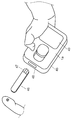
- FIG. 3 is a perspective view showing the configuration of the biological sample measuring instrument according to the first embodiment of the present invention.
- FIG. 4 is a functional block diagram of the biological sample measuring instrument according to the first embodiment of the present invention.
- FIG. 5 is a functional block diagram of the temperature information supply device (retainer) in the first embodiment of the present invention.
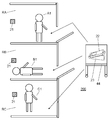
- FIG. 6 is a diagram for explaining an example of a usage state of the biological sample measurement device according to the first embodiment of the present invention.
- FIG. 1 is a perspective view showing a configuration of a biological sample measuring apparatus according to the first embodiment of the present invention.
- FIG. 2 is a diagram showing a cross-sectional configuration of the biological sample measurement device according to the first embodiment of the present invention.
- FIG. 3 is
- FIG. 7 is a flowchart showing an operation flow of the biological sample measurement device according to the first embodiment of the present invention.
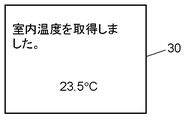
- FIG. 8A is a diagram showing an example of a screen displayed on the display unit of the biological sample measuring instrument according to the first embodiment of the present invention.
- FIG. 8B is a diagram showing an example of a screen displayed on the display unit of the biological sample measuring instrument according to the first embodiment of the present invention.
- FIG. 9 is a perspective view showing the configuration of the temperature information supply device according to the second embodiment of the present invention.
- FIG. 10 is a diagram illustrating a usage environment of the temperature information supply device and the biological sample measurement device according to the second embodiment of the present invention.
- FIG. 11 is a perspective view showing a configuration of a biological sample measuring instrument according to the second embodiment of the present invention.
- FIG. 8A is a diagram showing an example of a screen displayed on the display unit of the biological sample measuring instrument according to the first embodiment of the present invention.
- FIG. 8B is a diagram showing an example of
- FIG. 12 is a perspective view showing a configuration of a biological sample measuring instrument according to the second embodiment of the present invention.
- FIG. 13 is a functional block diagram of the biological sample measuring instrument according to the second embodiment of the present invention.
- FIG. 14 is a functional block diagram of a temperature information supply device according to the second embodiment of the present invention.
- FIG. 15 is a flowchart showing an operation flow of the biological sample measuring apparatus according to the second embodiment of the present invention.
- FIG. 16A is a diagram showing an example of a screen displayed on the display unit of the biological sample measuring instrument according to the second embodiment of the present invention.
- FIG. 16B is a diagram showing an example of a screen displayed on the display unit of the biological sample measuring instrument according to the second embodiment of the present invention.
- FIG. 16A is a diagram showing an example of a screen displayed on the display unit of the biological sample measuring instrument according to the second embodiment of the present invention.
- FIG. 16B is a diagram showing an example of a screen displayed on the display unit of the biological
- FIG. 17 is a perspective view showing the configuration of the biological sample measurement device according to the third embodiment of the present invention.
- FIG. 18 is a diagram showing a cross-sectional configuration of a biological sample measuring apparatus according to the third embodiment of the present invention.
- FIG. 19 is a perspective view showing a configuration of a biological sample measuring instrument according to the third embodiment of the present invention.
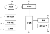
- FIG. 20 is a functional block diagram of a biological sample measuring instrument according to the third embodiment of the present invention.
- FIG. 21 is a functional block diagram of a temperature information supply device according to the third embodiment of the present invention.
- FIG. 22 is a flowchart showing an operation flow of the biological sample measuring apparatus according to the third embodiment of the present invention.
- FIG. 1 is a perspective view showing a configuration of a biological sample measuring apparatus 100 according to the first embodiment of the present invention.
- FIG. 2 is a diagram showing a cross-sectional configuration of the biological sample measuring apparatus 100.
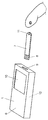
- FIG. 3 is a perspective view showing the configuration of the biological sample measuring instrument 1 according to the first embodiment of the present invention.
- the biological sample measuring device 100 supplies temperature information to a biological sample measuring instrument (hereinafter also simply referred to as a measuring instrument) 1 that measures a blood glucose level from blood, for example.
- a biological sample measuring instrument hereinafter also simply referred to as a measuring instrument
- a holder 2 that also serves as a temperature information supplier.
- the measuring instrument 1 is held by a holding unit 3 provided on the upper surface of the holder 2 when moving between hospital rooms in a hospital, for example.
- the holding unit 3 has a surface inclined downward from the front end to the rear end (from the right side to the left side as viewed in the drawing).
- a stopper 4 is provided at the lower end portion of the inclination to receive the measuring instrument 1 that contacts the inclined surface of the holding portion 3.
- the cage 2 has a temperature sensor 5 on the outer peripheral portion near the bottom. That is, in the present embodiment, the temperature sensor 5 (first temperature sensor) is provided outside the measuring instrument 1.
- the measuring instrument 1 has a plate-shaped main body case 6.
- a sensor mounting portion 9 for inserting a connection terminal 8 of a thin plate blood glucose level sensor 7 (an example of a biological sample measurement sensor) is provided at the distal end portion of the main body case 6.
- a display unit 10 for displaying a blood sugar level is provided on the upper surface of the main body case 6.
- the measurer attaches the connection terminal 8 of the blood glucose level sensor 7 to the sensor attachment portion 9, and in that state, drops the blood on the spotting portion 11 on the distal end side of the blood glucose level sensor 7. Thereby, the blood glucose level at that time is measured by the measuring unit 12 built in the main body case 6.
- FIG. 4 is a functional block diagram of the biological sample measuring instrument 1 according to the first embodiment of the present invention.
- the sensor mounting portion 9 is connected to the measuring portion 12.
- the measurement unit 12 is connected to the control unit 13.
- the control unit 13 is connected to a display unit 10 that displays a blood sugar level, a temperature information receiving unit 14 that receives temperature information from the cage 2, and a power source 15.
- control unit 13 includes a barcode reading unit 64 that reads a barcode ID (individual identification information, hereinafter referred to as ID) of each of a measurer, a patient, and a bottle (not shown) that houses the sensor. It is connected.
- ID barcode ID
- FIG. 5 is a functional block diagram of the temperature information supply device (retainer) 2 in the first embodiment of the present invention.
- the holding detection unit 16 that detects that the measuring device 1 is held in the holding unit 3 of the holder 2 is connected to the control unit 17. Further, the control unit 17 includes a temperature sensor 5 (see FIG. 1) disposed on the outer periphery of the cage 2, and a temperature information transmission unit that sends the detected temperature detected by the temperature sensor 5 to the temperature information reception unit 14 of the measuring device 1. 18 and a power source 19 are connected.
- control unit 17 of the holder 2 can detect that the measuring device 1 is held by the holding unit 3.
- maintenance detection part 16 can be comprised with a general contact type switch.
- a temperature information receiving unit 14 having a metal terminal shape is provided on the lower surface of the measuring instrument 1.
- a metal plate spring-shaped temperature information transmitting unit 18 is provided on the upper surface of the holding unit 3.
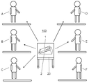
- FIG. 6 is a diagram for explaining an example of a usage state of the biological sample measurement apparatus 100 according to the first embodiment of the present invention.
- FIG. 6 shows a hospital room. Assume that patients A to F are waiting in a hospital room with three curtains on the left and right sides of the page. And the state where the measurement person (for example, nurse) carried the measuring instrument 1 and the holder 2 on the wagon 20 and carried it to the central part of the hospital room is shown.
- the measurement person for example, nurse
- measurement related information such as a patient ID and a biological sample sensor ID is collected for each measurement.
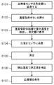
- FIG. 7 is a flowchart showing an operation flow of the biological sample measuring apparatus 100 according to the first embodiment of the present invention.
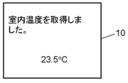
- 8A and 8B are diagrams showing examples of screens displayed on the display unit 10 of the biological sample measuring instrument 1 according to the first embodiment of the present invention.
- measurement-related information such as a measurer ID, a patient ID, and a bottle ID containing a sensor is collected for each measurement.
- the measurer picks up the measuring instrument 1 from the holder 2 and reads the measurer ID, patient ID, and bottle ID using the barcode reading unit 64 of the measuring instrument 1 (S1). .
- components for example, components such as the barcode reading unit 64, the control unit 13, or the display unit 10) built in the measuring instrument 1 operate.
- a temperature rise occurs in the measuring instrument 1.
- the temperature rise inside the measuring instrument 1 does not affect the temperature sensor 5 of the holder 2. That is, the temperature sensor 5 of the cage 2 can detect the temperature in the hospital room that is the measurement environment.
- the measurer attaches the connection terminal 8 of the blood glucose level sensor 7 to the sensor attachment portion 9 in order to measure the blood glucose level of the patient A. Then, power is supplied from the power supply 15 to the control unit 13 of the measuring instrument 1. At this time, as shown in FIG. 8A, the display unit 10 displays a message “Place the measuring device on the table (acquire the room temperature)” (S2).
- Measurer who has read this message returns the measuring instrument 1 to the holder 2. And a patient's A finger is punctured using a puncture tool (not shown). And as shown in FIG. 3, blood is made to flow out slightly.
- the holder 2 detects that the measuring instrument 1 is held by the holding unit 3 by the holding detection unit 16.
- the holding detection unit 16 notifies the holding information to the control unit 17 (S3). It is assumed that the retainer 2 is provided with a power switch (not shown), the power switch is turned on in advance, and power is supplied from the power source 19 to the control unit 17.
- the control unit 17 notified of the holding information detects the temperature in the hospital room using the temperature sensor 5.
- the control unit 17 transmits the detected temperature to the measuring instrument 1 via the temperature information transmission unit 18.
- the control unit 13 of the measuring instrument 1 acquires the transmitted detected temperature via the temperature information receiving unit 14. Then, for example, as shown in FIG. 8B, a message “Indoor temperature has been acquired, 23.5 ° C.” is displayed on the display unit 10 (S4).
- the operation in which the control unit 13 of the measuring instrument 1 receives the detected temperature from the holder 2 is performed during the puncturing operation of the patient A.
- the measurer who has finished the puncturing operation checks the temperature of the hospital room acquired by looking at the display on the display unit 10 of the measuring instrument 1. Then, the measurer removes the measuring instrument 1 from the holder 2 and deposits blood on the spotting part 11 on the distal end side of the blood glucose level sensor 7 (S5). Then, the blood glucose level of the patient A is measured by the measuring unit 12 (S6).
- control unit 13 corrects the measurement value measured by the measurement unit 12 by the detected temperature (measurement environment temperature) detected by the temperature sensor 5 of the cage 2 (S7).
- amendment by the detected temperature of a measured value is abbreviate
- the temperature detected by the temperature sensor 5 of the cage 2 provided outside the measuring instrument 1 is used for correction.
- the blood glucose level measurement reaction in the blood glucose level sensor 7 is performed in the spotting section 11 as shown in FIG. That is, the reaction is performed at a measurement environment temperature outside the measuring device 1. Since this reaction varies greatly depending on the temperature, it is necessary to correct the measured value based on the measurement environment temperature.
- the temperature sensor 5 has been arranged inside the measuring instrument 1. For this reason, the temperature detected by the temperature sensor 5 is affected by the temperature rise of components (for example, components such as the barcode reading unit 64, the control unit 13, and the display unit 10) mounted in the measuring instrument 1. There is. As a result, the measured value may be corrected by a temperature different from the environmental temperature of the spotting part 11 of the blood glucose level sensor 7 outside the measuring instrument 1, and the measured value varies.
- components for example, components such as the barcode reading unit 64, the control unit 13, and the display unit
- the temperature detected by the temperature sensor 5 and the temperature rise of components for example, the barcode reading unit 64, the control unit 13, and the display unit 10) built in the measuring instrument 1, There is also a method for estimating the measurement environment temperature of a certain spot 11.
- the measured value may be corrected by a temperature different from the measurement environment temperature of the spotting portion 11, and the measured value may vary.
- the temperature sensor 5 is disposed on the outer peripheral portion of the cage 2 provided separately from the measuring device 1. For this reason, the temperature sensor 5 measures and detects the temperature outside the measuring instrument 1, that is, the temperature (measurement environment temperature) corresponding to the environment temperature of the spotting part 11 where the reaction of blood glucose level measurement is performed. Can do. And the control part 13 correct
- the correction can be performed using the temperature information corresponding to the measurement environment of the spotting section 11, so that the variation of the measured value can be suppressed.
- control unit 13 displays the corrected blood glucose level on the display unit 10, and the measurement of the patient A is completed (S8).
- the measuring instrument 1 when the measuring instrument 1 acquires the measurement environment temperature, the measuring instrument 1 may be placed on the holding unit 3 of the holder 2. For this reason, the time during which the measuring instrument 1 and the holder 2 are in contact with each other can be shortened, and the heat inside the measuring instrument 1 is not easily transmitted to the temperature sensor 5.
- the temperature sensor 5 is disposed on the outer peripheral portion near the bottom of the cage 2. That is, the temperature sensor 5 is arranged at a position as far as possible from the measuring device 1 placed on the holding unit 3 of the holder 2. For this reason, even if the measuring device 1 is placed on the holding portion 3 of the holder 2, the heat inside the measuring device 1 is not easily transmitted to the temperature sensor 5.
- the measurer sequentially performs the steps from Step S1 to Step S8 of FIG. 7 described above on the patients B to F, and continuously measures the blood glucose level.
- the temperature rise due to energization of the components (for example, the barcode reading unit 64, the control unit 13, and the display unit 10) built in the measuring instrument 1 is integrated and increased.
- the measuring instrument 1 is frequently held by the measurer. For this reason, the heat of the measurer's hand is transmitted to the inside of the measuring instrument 1 and the internal temperature of the measuring instrument 1 is increased.
- the temperature sensor 5 is disposed on the outer peripheral portion of the cage 2 provided separately from the measuring device 1. Therefore, even during continuous measurement in such hospital work, the temperature sensor 5 of the cage 2 can measure and detect the temperature corresponding to the measurement environment temperature of the spotting section 11. As a result, the correction can be performed using the temperature information corresponding to the measurement environment of the spotting section 11, so that variations in measured values can be suppressed.
- thermosensor 5 it is also conceivable to provide a temperature sensor 5 on the outer peripheral surface of the measuring instrument 1 and measure the outside air at the measurement location. However, if it does so, a measurer's hand may touch the temperature sensor 5, and an appropriate temperature cannot always be measured.
- the biological sample measuring device 200 includes a biological sample measuring device 22 and one or a plurality of temperature information supply devices 21.
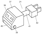
- FIG. 9 is a perspective view showing the configuration of the temperature information supply unit 21 in the second embodiment of the present invention.
- FIG. 10 is a diagram showing a use environment of the temperature information supply device 21 and the biological sample measurement device 22 in the second embodiment of the present invention.
- the temperature information supply device 21 as shown in FIG. 9 is arranged and used for each of the private rooms RA to RC of the hospital as shown in FIG.
- FIG. 11 is a perspective view showing the configuration of the biological sample measuring instrument 22 in the second embodiment of the present invention.
- a biological sample measuring device 22 measures a blood glucose level from blood, for example.
- the measuring device 22 is held by a holding portion 24 provided on the upper surface of the holding device 23 when moving between hospital rooms in a hospital, for example.
- the holding portion 24 has a surface inclined downward from the front end to the rear end (from the right side to the left side as viewed in the drawing).
- a stopper 25 is provided at the lower end portion of the inclination to receive the measuring device 22 that contacts the inclined surface of the holding portion 24.
- FIG. 12 is a perspective view showing the configuration of the biological sample measuring instrument 22 in the second embodiment of the present invention.
- the measuring instrument 22 has a plate-shaped main body case 26.
- a sensor mounting portion 29 for inserting a connection terminal 28 of a thin blood glucose level sensor 27 is provided at the distal end portion of the main body case 26.
- a display unit 30 for displaying a blood sugar level and a temperature acquisition button 31 to which a trigger for acquiring temperature information from the temperature information supply device 21 is input are provided.
- a temperature information receiving unit 32 that performs communication using radio waves or light to receive temperature information from the temperature information supply device 21 is provided at the tip of the main body case 26.
- the temperature information receiving unit 32 performs general infrared communication with the temperature information transmitting unit 40 of the temperature information supply unit 21.
- the measurer attaches the connection terminal 28 of the blood glucose level sensor 27 to the sensor attachment portion 29, and in that state, drops the blood on the spotting portion 33 on the distal end side of the blood glucose level sensor 27. Thereby, the blood glucose level at that time is measured by the measuring unit 34 built in the main body case 26.
- FIG. 13 is a functional block diagram of the biological sample measuring instrument 22 in the second embodiment of the present invention.
- the sensor mounting portion 29 is connected to the measuring portion 34.
- the measurement unit 34 is connected to the control unit 35.
- the control unit 35 is connected to a display unit 30 for displaying a blood sugar level, a temperature acquisition button 31, a temperature information receiving unit 32, and a power source 36.
- the temperature information supply unit 21 has a polyhedral main body case 37.
- a temperature sensor 38 that acquires the external temperature of the temperature information supply device 21 is disposed on the outer periphery of the main body case 37.
- a display unit 39 for displaying temperature information acquired by the temperature sensor 38 is provided on the rear end side (left side in FIG. 9) of the main body case 37.
- a temperature information transmitting unit 40 that performs radio wave or optical communication with the temperature information receiving unit 32 of the measuring instrument 22 is provided on the rear end side of the main body case 37.
- the temperature information transmitting unit 40 is configured to perform general infrared communication with the temperature information receiving unit 32 of the measuring instrument 22.
- a power plug 42 is connected to the front end side (right side in FIG. 9) of the main body case 37 via a connection portion 41. By inserting the power plug 42 into a general outlet (for example, AC 100 V), power is supplied to the temperature information supplier 21.
- a general outlet for example, AC 100 V
- FIG. 14 is a functional block diagram of the temperature information supplier 21 in the second embodiment of the present invention.
- the temperature information transmission unit 40 that transmits temperature information to the measuring instrument 22 is connected to the control unit 43.
- a display unit 39, a temperature sensor 38, and a power plug 42 are connected to the control unit 43.
- FIG. 10 shows a hospital room. Assume that the patients A1 to C1 are waiting in the individual rooms RA to RC of the hospital room, respectively. Then, it is assumed that the measurer has put the measuring device 22 and the holder 23 on the wagon 44 in order to sequentially measure the blood glucose levels of the patients A1 to C1.
- the power plug 42 of the temperature information supply device 21 is inserted in advance into an outlet provided on the wall of each of the individual rooms RA to RC, for example.
- the temperature information supplier 21 is energized while attached to the wall.
- the control unit 43 of the temperature information supply device 21 periodically detects the room temperature in the individual rooms RA to RC using the temperature sensor 38 provided on the outer periphery of the main body case 37. Further, the detected temperature is displayed on the display unit 39 by the control unit 43.
- FIG. 15 is a flowchart showing an operation flow of the biological sample measuring apparatus 200 according to the second embodiment of the present invention.
- FIGS. 16A and 16B are diagrams showing an example of a screen displayed on the display unit 30 of the biological sample measuring instrument 22 in the second embodiment of the present invention.
- the measurer pushes the wagon 44 and enters the private room RA of the patient A1.
- the measurer takes out the measuring instrument 22 from the holder 23 and attaches the connection terminal 28 of the blood glucose level sensor 27 to the sensor attaching portion 29 as shown in FIG.
- power is supplied from the power source 36 to the control unit 35 of the measuring instrument 22, and a message “Please obtain the room temperature” as shown in FIG. 16A is displayed on the display unit 30. (S101).
- the measurer who has read this message points the temperature information receiving unit 32 at the tip of the measuring device 22 toward the temperature information transmitting unit 40 of the temperature information supplying device 21 attached to the wall of the bed, and acquires the temperature of the measuring device 22.
- the button 31 (see FIG. 12) is pressed (S102).
- a temperature acquisition request is transmitted from the temperature information receiving unit 32 to the temperature information transmitting unit 40.
- the control unit 43 of the temperature information supply device 21 receives this temperature acquisition request via the temperature information transmission unit 40.
- the control unit 43 detects the room temperature in the private room RA using the temperature sensor 38 and displays it on the display unit 39.
- control unit 43 transmits the temperature information of the detected temperature (room temperature, that is, the measurement environment temperature) in the private room RA from the temperature information transmission unit 40 to the temperature information reception unit 32 of the measuring instrument 22.
- the control unit 35 receives the temperature information via the temperature information receiving unit 32.
- the display unit 30 reads “Indoor temperature acquired, 23.5 ° C.” It is displayed (S103).
- the measurer can confirm whether or not the room temperature has been correctly acquired by looking at this display and the temperature displayed on the display unit 39 of the temperature information supplier 21.
- the measurer takes out the puncture tool (not shown) and punctures the finger of the patient A1 to expose the blood. Then, as shown in FIG. 12, the measurer drops blood on the spotting portion 33 on the distal end side of the blood glucose level sensor 27 (S104). Thereby, the blood glucose level of the patient A1 is measured by the measuring unit 34 (S105).
- the measurement value measured by the measurement unit 34 is corrected by the detected temperature (measurement environment temperature) detected by the temperature sensor 38 of the temperature information supply unit 21 (S106).
- the temperature detected by the temperature sensor 38 of the temperature information supply device 21 provided separately from the measuring device 22 is used for correcting the measured value.
- the blood glucose level measurement reaction in the blood glucose level sensor 27 is performed in the spotting section 33 as shown in FIG. That is, the reaction is performed at the measurement environment temperature (room temperature) outside the measuring device 22. Since this reaction varies greatly depending on the temperature, it is necessary to correct the measured value based on the measurement environment temperature.
- the measurement environment temperature used for correction is acquired by the temperature sensor 38.
- the temperature sensor 38 has been arranged inside the measuring device 22.
- the temperature detected by the temperature sensor 38 may be affected by the temperature rise of components (for example, components such as the control unit 35 and the display unit 30) mounted in the measuring instrument 22.
- the measured value may be corrected by a temperature different from the environmental temperature of the spotting part 33 of the blood glucose level sensor 27 outside the measuring instrument 22, and in this case, the measured value varies.
- the temperature detected by the temperature sensor 38 and the temperature rise of components (for example, the control unit 35 and the display unit 30) built in the measuring instrument 22 are used to detect the spotting unit 33 outside the measuring instrument 22.
- the measured value may be corrected by a temperature different from the measurement environment temperature of the spotting portion 33, and the measured value may vary.
- the temperature sensor 38 is disposed on the outer peripheral portion of the temperature information supply device 21 provided separately from the measuring device 22. For this reason, the temperature sensor 38 can measure and detect the temperature outside the measuring instrument 22, that is, the measurement environment temperature (indoor temperature) of the spotting portion 33 where the reaction of blood glucose level measurement is performed. And the control part 35 correct
- control unit 35 displays the corrected blood glucose level on the display unit 30, and the measurement of the patient A1 is completed (S107).
- the measurer pushes the wagon 44 and sequentially visits the individual rooms RB to RC of the patients B1 to C1 to perform measurement as shown in FIG.
- the air conditioner may be adjusted for each of the private rooms RA to RC.
- the room temperature may be set higher than the designated temperature
- the room temperature may be set lower than the designated temperature. For this reason, a temperature difference of several degrees may occur between the room temperature of the private room RA and the room temperature of the private room RB.
- the temperature information supply device 21 since the temperature information supply device 21 is placed in the energized state in advance in the individual rooms RA to RC, an accurate room temperature can be detected.
- the measurer After moving from the private room RA to the private room RB, the measurer attaches the connection terminal 28 of the blood glucose level sensor 27 to the sensor attachment portion 29 as described above, and in this state, attaches the spot on the tip side of the blood glucose level sensor 27 Blood is spotted on the part 33 and the blood sugar level is measured.
- the blood glucose level sensor 27 used at this time has a thin plate shape as shown in FIG. For this reason, even when there is a temperature difference of several degrees between the two rooms when moving from the private room RA to the private room RB, the thin plate-shaped blood glucose level sensor 27 has a large surface area relative to the volume. It becomes the same temperature as the room temperature of the destination private room RB.
- the temperature sensor 38 disposed on the outer periphery of the temperature information supply unit 21 measures and detects the room temperature of the individual room RB, that is, the temperature corresponding to the measurement environment temperature of the spotting section 33. And the measuring device 22 correct
- thermosensor 38 it is also conceivable to provide a temperature sensor 38 on the outer peripheral surface of the measuring instrument 22 and measure the outside air at the measurement location. However, if it does so, a measurer's hand may touch the temperature sensor 38, and an appropriate temperature cannot always be measured.
- the temperature information transmission unit 40 is configured to perform general infrared communication.
- the temperature information transmission unit 40 may be configured to perform radio communication.
- radio wave communication When radio wave communication is used, the temperature information of the adjacent room can be prevented from interfering by shortening the transmission / reception distance.
- FIG. 17 is a perspective view showing a configuration of a biological sample measuring apparatus 300 according to the third embodiment of the present invention.
- FIG. 18 is a diagram showing a cross-sectional configuration of the biological sample measuring apparatus 300.
- FIG. 19 is a perspective view showing a configuration of a biological sample measuring instrument 1a according to the third embodiment of the present invention.
- the biological sample measuring apparatus 300 includes a biological sample measuring device (also referred to as a measuring device) 1a and a temperature information supply device (also referred to as a holder) 2a.
- a biological sample measuring device also referred to as a measuring device
- a temperature information supply device also referred to as a holder
- the biological sample measurement apparatus 300 is also compatible with emergency measurement in a hospital. For example, in a hospital, it is necessary to take out the measuring device 1a urgently to a patient who has been urgently transported, and perform measurement at a place away from the holder 2a. During such an emergency measurement, the measuring device 1a may not be able to acquire temperature information from the temperature sensor 5a (first temperature sensor, see FIG. 18) of the cage 2a.
- the temperature sensor 5a first temperature sensor, see FIG. 18
- the temperature sensor 51 (second temperature sensor) is also provided in the measuring instrument 1a.
- retainer 2a has the air blower 57 (refer FIG. 18) which ventilates the measuring device 1a.
- the measuring instrument 1a acquires temperature information from the temperature sensor 51 provided therein, and corrects the measured value. Then, after the emergency measurement, when the measurer holds the measuring instrument 1a in the holder 2a, the blower 57 of the holder 2a cools the temperature sensor 51 of the measuring instrument 1a to the room temperature.
- the measuring instrument 1a can acquire accurate temperature information (indoor temperature, that is, measurement environment temperature) from the temperature sensor 51, thereby suppressing variations in measurement values. Can do.
- the measuring instrument 1a measures a blood glucose level from blood, for example. As shown in FIG. 18, the measuring instrument 1a is detachably held by the holder 2a during measurement other than during measurement, for example, when moving between hospital rooms.
- the measuring instrument 1a has a plate-like main body case 45 as shown in FIG.
- An opening 48 for inserting a terminal portion 47 of a thin plate blood glucose level sensor (an example of a biological sample measurement sensor) 46 is provided at the distal end portion of the main body case 45.
- a display unit 49 for displaying the blood sugar level is provided on the upper surface of the main body case 45.
- the measurer attaches blood to the detection portion (not shown) at the tip of the blood glucose level sensor 46 with the terminal portion 47 of the blood glucose level sensor 46 inserted into the opening 48, the blood glucose level at that time Is measured by the measuring unit 50 (see FIG. 20) built in the main body case 45.
- FIG. 20 is a functional block diagram of the biological sample measuring instrument 1a according to the third embodiment of the present invention.
- a communication unit 53 As shown in FIG. 20, a communication unit 53, a measurement unit 50, a display unit 49 and a temperature sensor 51 are connected to the control unit 52.
- the measuring device 1a may be taken out from the holder 2a for measurement.
- the temperature information is acquired by the temperature sensor 51 (see FIG. 18) provided in the vicinity of the opening 48 in the main body case 45 instead of acquiring the temperature from the cage 2a.
- the control unit 52 acquires temperature information from the temperature sensor 51 and corrects the measured value based on the temperature information.
- the corrected blood glucose level is displayed on the display unit 49.
- a bar code reading unit (not shown) of the measuring instrument 1a, that is, a measurer ID, a patient ID, or a bottle ID Etc. may not be read.
- the measurer takes the measuring instrument 1a back to the place of the holder 2a, and holds the measuring instrument 1a in the holder 2a as shown in FIG.
- the retainer 2 a is provided with a retaining portion 54 that is inclined downward from one end to the other end (from the right to the left as viewed in the drawing). Further, a stopper 55 that receives the measuring instrument 1 a that contacts the inclined surface of the holding portion 54 is provided on the inclined lower end side.
- the opening 48 side of the measuring instrument 1 a is positioned in contact with the stopper 55.
- air is blown from the upper air blowing port 56 to cool the opening 48 side of the main body case 45 of the measuring instrument 1a, that is, the side where the temperature sensor 51 in the main body case 45 is provided, and the opening The main body case 45 can be cooled via 48.
- a fan 57 is provided in the cage 2a.
- the blower 57 and the blower port 56 are connected by an air passage 58.
- a sterilizer 59 that generates OH radicals or active oxygen is disposed in the air passage 58.
- the body case 45 from which the blood glucose level measurement is completed and the blood glucose level sensor 46 is removed from the opening 48 is held by the holding portion 54 of the holder 2a as shown in FIG. Assumed state.
- the measuring instrument 1a is cooled by the wind blown from the blower 57 (the indoor air as the measurement place or the outdoor air) through the air passage 58 and the air blowing port 56.
- the temperature detected by the temperature sensor 51 shows a value that approximates the temperature at the measurement location. Therefore, the temperature correction performed in the control unit 52 described above is appropriately performed.
- FIG. 21 is a functional block diagram of the cage 2a according to the third embodiment of the present invention.
- the blower 57 and the sterilizer 59 are connected to the control unit 60 (second control unit).
- the control unit 60 also includes a temperature sensor 5a that detects the temperature of the measurement location (measurement environment temperature), a mounting detector 61 that detects that the measuring device 1a is mounted on the holding unit 54 of the holder 2a, and the measuring device 1a.
- a communication unit 62 that performs infrared communication with the communication unit 53 and a power source 63.
- FIG. 22 is a flowchart showing an operation flow of the biological sample measurement apparatus 300 according to the third embodiment of the present invention.
- the mounting detector 61 detects the mounting of the measuring instrument 1a (S201).
- blower 57 and the sterilizer 59 are driven by the controller 60 of the cage 2a (S202). Thereby, ventilation is started from the blower 57 to the opening 48 part of the main body case 45 through the air passage 58 and the blower opening 56, and cooling is started from the opening 48 part.
- the vicinity of the opening 48 is sterilized by OH radicals or active oxygen generated in the sterilizer 59.
- temperature information of the detected temperature from the temperature sensor 51 of the measuring instrument 1 a is supplied to the control unit 60 via the communication unit 53 and the communication unit 62. Further, the detected temperature from the temperature sensor 5a of the cage 2a is also supplied to the control unit 60 (S203, S204).
- the controller 60 of the holder 2a compares the detected temperature detected by the temperature sensor 51 of the measuring instrument 1a with the detected temperature detected by the temperature sensor 5a of the holder 2a. And the control part 60 continues ventilation and disinfection until the detection temperature of the temperature sensor 51 of the measuring device 1a approaches the preset temperature set in the vicinity of the detection temperature of the temperature sensor 5a of the holder
- the air blown from the air blowing port 56 is blown into the main body case 45 through the opening 48 of the main body case 45.
- the inside of main body case 45 can be directly cooled by this ventilation.
- the inside of the main body case 45 can be quickly cooled. For this reason, the temperature in the main body case 45 does not increase significantly compared to the room temperature or the outside air temperature as the measurement location.
- the measurement error can be reduced.
- the power source of the measuring instrument 1a is constituted by a rechargeable battery
- the charging unit when the charging unit is provided in the holder 2a and the measuring instrument 1a is held in the holder 2a, the rechargeable battery Can be charged.
- the rechargeable battery may be heated by charging, and the internal temperature of the main body case 45 may increase.
- the measuring device 1a is held by the retainer 2a, cooling is performed by the blower 57 of the retainer 2a. Does not increase significantly from the room temperature or the outside temperature, which is the measurement location.
- the measurement error can be reduced.
- the measuring instrument 1a is held by the holder 2a and is cooled by the blower 57 so that the temperature inside the measuring instrument 1a becomes the room temperature.
- the blower 57, the blower port 56 and the air passage 58 constituting the cooling mechanism are provided on the rear end side of the cage 2a, and the opening of the main body case 45 of the measuring instrument 1a. 48 is covered.
- the tip portion from the central portion of the measuring instrument 1a is not covered by the cooling mechanism of the holder 2a and is in an open state.
- the middle part of the measuring instrument 1a can be grasped using, for example, the thumb and the index finger. Thereby, the measuring device 1a can be easily taken out from the holder 2a.
- the measuring instrument 1a holds the temperature information (measurement environment temperature) of the temperature sensor 5a of the holder 2a in the same manner as described in the first and second embodiments.
- the measured value is corrected with the received temperature information received via the communication unit 62 of the measuring instrument 2a and the communication unit 53 of the measuring instrument 1a.
- each biological sample measurement device has been described as measuring a blood glucose level of a human body.
- the present invention is not limited to this example.
- the biological sample measurement device includes a device that measures various biological samples that may cause variations in measurement values due to temperature changes in the measurement environment.
- the biological sample measuring instrument since it is possible to produce a special effect that variation in measured values can be suppressed, the biological sample measuring instrument and the temperature at which temperature information is supplied to the biological sample measuring instrument. It is useful as a biological sample measuring device equipped with an information supply device.
Landscapes
- Health & Medical Sciences (AREA)
- Engineering & Computer Science (AREA)
- Life Sciences & Earth Sciences (AREA)
- Chemical & Material Sciences (AREA)
- Physics & Mathematics (AREA)
- Hematology (AREA)
- Biomedical Technology (AREA)
- Immunology (AREA)
- Molecular Biology (AREA)
- General Physics & Mathematics (AREA)
- Urology & Nephrology (AREA)
- Pathology (AREA)
- General Health & Medical Sciences (AREA)
- Biochemistry (AREA)
- Analytical Chemistry (AREA)
- Food Science & Technology (AREA)
- Medicinal Chemistry (AREA)
- Biophysics (AREA)
- Mechanical Engineering (AREA)
- General Engineering & Computer Science (AREA)
- Combustion & Propulsion (AREA)
- Diabetes (AREA)
- Biotechnology (AREA)
- Cell Biology (AREA)
- Microbiology (AREA)
- Human Computer Interaction (AREA)
- Optics & Photonics (AREA)
- Medical Informatics (AREA)
- Chemical Kinetics & Catalysis (AREA)
- Electrochemistry (AREA)
- Databases & Information Systems (AREA)
- Fluid Mechanics (AREA)
- Investigating Or Analysing Biological Materials (AREA)
- Measurement Of The Respiration, Hearing Ability, Form, And Blood Characteristics Of Living Organisms (AREA)
Abstract
Priority Applications (3)
| Application Number | Priority Date | Filing Date | Title |
|---|---|---|---|
| JP2013502183A JP5824507B2 (ja) | 2011-03-01 | 2012-02-23 | 生体試料測定装置 |
| US13/978,031 US9587989B2 (en) | 2011-03-01 | 2012-02-23 | Biological sample measurement device |
| US15/409,486 US9921227B2 (en) | 2011-03-01 | 2017-01-18 | Biological information measurement method |
Applications Claiming Priority (6)
| Application Number | Priority Date | Filing Date | Title |
|---|---|---|---|
| JP2011-043480 | 2011-03-01 | ||
| JP2011043482 | 2011-03-01 | ||
| JP2011-043483 | 2011-03-01 | ||
| JP2011043483 | 2011-03-01 | ||
| JP2011043480 | 2011-03-01 | ||
| JP2011-043482 | 2011-03-01 |
Related Child Applications (2)
| Application Number | Title | Priority Date | Filing Date |
|---|---|---|---|
| US13/978,031 A-371-Of-International US9587989B2 (en) | 2011-03-01 | 2012-02-23 | Biological sample measurement device |
| US15/409,486 Continuation US9921227B2 (en) | 2011-03-01 | 2017-01-18 | Biological information measurement method |
Publications (1)
| Publication Number | Publication Date |
|---|---|
| WO2012117699A1 true WO2012117699A1 (fr) | 2012-09-07 |
Family
ID=46757644
Family Applications (1)
| Application Number | Title | Priority Date | Filing Date |
|---|---|---|---|
| PCT/JP2012/001224 Ceased WO2012117699A1 (fr) | 2011-03-01 | 2012-02-23 | Dispositif de mesure d'échantillon biologique |
Country Status (3)
| Country | Link |
|---|---|
| US (2) | US9587989B2 (fr) |
| JP (1) | JP5824507B2 (fr) |
| WO (1) | WO2012117699A1 (fr) |
Families Citing this family (2)
| Publication number | Priority date | Publication date | Assignee | Title |
|---|---|---|---|---|
| JP5749806B2 (ja) * | 2011-11-01 | 2015-07-15 | パナソニックヘルスケアホールディングス株式会社 | 生体試料測定装置 |
| US9841391B2 (en) | 2014-09-09 | 2017-12-12 | LifeSan Scotland Limited | Hand-held test meter with integrated thermal channel |
Citations (4)
| Publication number | Priority date | Publication date | Assignee | Title |
|---|---|---|---|---|
| JP2002521692A (ja) * | 1998-07-31 | 2002-07-16 | アボット・ラボラトリーズ | データ管理システムを含む被分析物検査器具システム |
| JP2007526440A (ja) * | 2003-06-03 | 2007-09-13 | バイエル・ヘルスケア・エルエルシー | 携帯型医療診断装置 |
| WO2009119118A1 (fr) * | 2008-03-27 | 2009-10-01 | パナソニック株式会社 | Dispositif de mesure d'échantillon, système de mesure d'échantillon et procédé de mesure d'échantillon |
| WO2010049669A1 (fr) * | 2008-10-27 | 2010-05-06 | Lifescan Scotland Limited | Procédés et dispositifs pour atténuer des événements de décharge électrostatique |
Family Cites Families (10)
| Publication number | Priority date | Publication date | Assignee | Title |
|---|---|---|---|---|
| US8688188B2 (en) * | 1998-04-30 | 2014-04-01 | Abbott Diabetes Care Inc. | Analyte monitoring device and methods of use |
| US6946299B2 (en) | 2002-04-25 | 2005-09-20 | Home Diagnostics, Inc. | Systems and methods for blood glucose sensing |
| US7354429B2 (en) * | 2003-05-27 | 2008-04-08 | Integrated Sensing Systems, Inc. | Device and method for detecting and treating chemical and biological agents |
| US20060229502A1 (en) | 2003-06-03 | 2006-10-12 | Bayer Healthcare Llc | Portable medical diagnostic apparatus |
| WO2007075919A2 (fr) * | 2005-12-22 | 2007-07-05 | Honeywell International Inc. | Systeme d'analyseur portatif d'echantillons |
| US8696597B2 (en) | 2006-04-03 | 2014-04-15 | Nipro Diagnostics, Inc. | Diagnostic meter |
| JP5773241B2 (ja) * | 2007-10-15 | 2015-09-02 | バイエル・ヘルスケア・エルエルシーBayer HealthCareLLC | 試験センサの温度を決定する方法及びアセンブリ |
| WO2009119116A1 (fr) | 2008-03-27 | 2009-10-01 | パナソニック株式会社 | Procédé de mesure de la température d’un environnement, procédé de mesure d’échantillon liquide, et dispositif de mesure |
| WO2010017192A1 (fr) * | 2008-08-05 | 2010-02-11 | Ph Diagnostics Inc. | Appareil, procédé et système pour déterminer un état physiologique chez un mammifère |
| US8140294B2 (en) * | 2009-06-05 | 2012-03-20 | Roche Diagnostics Operations, Inc. | Temperature estimations in a blood glucose measuring device |
-
2012
- 2012-02-23 WO PCT/JP2012/001224 patent/WO2012117699A1/fr not_active Ceased
- 2012-02-23 US US13/978,031 patent/US9587989B2/en active Active
- 2012-02-23 JP JP2013502183A patent/JP5824507B2/ja active Active
-
2017
- 2017-01-18 US US15/409,486 patent/US9921227B2/en active Active
Patent Citations (4)
| Publication number | Priority date | Publication date | Assignee | Title |
|---|---|---|---|---|
| JP2002521692A (ja) * | 1998-07-31 | 2002-07-16 | アボット・ラボラトリーズ | データ管理システムを含む被分析物検査器具システム |
| JP2007526440A (ja) * | 2003-06-03 | 2007-09-13 | バイエル・ヘルスケア・エルエルシー | 携帯型医療診断装置 |
| WO2009119118A1 (fr) * | 2008-03-27 | 2009-10-01 | パナソニック株式会社 | Dispositif de mesure d'échantillon, système de mesure d'échantillon et procédé de mesure d'échantillon |
| WO2010049669A1 (fr) * | 2008-10-27 | 2010-05-06 | Lifescan Scotland Limited | Procédés et dispositifs pour atténuer des événements de décharge électrostatique |
Also Published As
| Publication number | Publication date |
|---|---|
| US9587989B2 (en) | 2017-03-07 |
| US20170122956A1 (en) | 2017-05-04 |
| JPWO2012117699A1 (ja) | 2014-07-07 |
| US9921227B2 (en) | 2018-03-20 |
| JP5824507B2 (ja) | 2015-11-25 |
| US20130279539A1 (en) | 2013-10-24 |
Similar Documents
| Publication | Publication Date | Title |
|---|---|---|
| JP7642134B2 (ja) | スパイロメトリデータを収集するための方法およびシステム | |
| JP2022107538A (ja) | 医療機器を滅菌する装置及び方法 | |
| AU2023274057A1 (en) | System and method for wirelessly charging a medical device battery | |
| ES2284163T3 (es) | Procedimiento y aparato para marcar eventos predeterminados con un biosensor. | |
| CN114787737A (zh) | 用于受控污染区域的移动监测设备 | |
| US8647575B2 (en) | Device for measuring blood component | |
| CN110237880A (zh) | 分析设备 | |
| CN101051045A (zh) | 利用rfid校准分析物测量仪的适用方法 | |
| JP2019514606A (ja) | 分析物測定システムおよび初期化方法 | |
| EP2633310A1 (fr) | Dispositifs et systèmes de mesure d'analyte, et composants et procédés associés | |
| KR101259236B1 (ko) | 비침습형 의료 데이터 수집 어셈블리 | |
| KR102128652B1 (ko) | 적외선 귀 체온계 | |
| JP5862330B2 (ja) | 生体情報測定システムおよび生体情報測定機器 | |
| KR20160102492A (ko) | 분석물 측정기용 검사 스트립 삽입 구동 기구 | |
| CN109124598A (zh) | 健康一体机及其控制方法 | |
| JP5824507B2 (ja) | 生体試料測定装置 | |
| JP5516289B2 (ja) | グルコース濃度測定器システム、グルコースセンサチップ携行ケース | |
| KR20170076613A (ko) | 소변 내 활성 산소 자가 계측용 키트 및 이를 이용한 활성 산소 계측기 | |
| JP4598825B2 (ja) | 穿刺装置及び穿刺チップ | |
| US20240161287A1 (en) | Medical device inspection system with external inspection device | |
| JP2013137679A (ja) | 生体情報測定システムおよび生体情報測定機器 | |
| TWI463428B (zh) | 自動移動健康照護裝置 | |
| JP3971113B2 (ja) | 内視鏡システムおよび処置具管理システム | |
| KR102327768B1 (ko) | Nfc를 이용한 내시경 스코프 세척 및 소독 관제 시스템 | |
| US9625441B2 (en) | Biological sample measurement device |
Legal Events
| Date | Code | Title | Description |
|---|---|---|---|
| 121 | Ep: the epo has been informed by wipo that ep was designated in this application |
Ref document number: 12752615 Country of ref document: EP Kind code of ref document: A1 |
|
| ENP | Entry into the national phase |
Ref document number: 2013502183 Country of ref document: JP Kind code of ref document: A |
|
| WWE | Wipo information: entry into national phase |
Ref document number: 13978031 Country of ref document: US |
|
| NENP | Non-entry into the national phase |
Ref country code: DE |
|
| 122 | Ep: pct application non-entry in european phase |
Ref document number: 12752615 Country of ref document: EP Kind code of ref document: A1 |