WO2012117771A1 - 多軸駆動装置 - Google Patents
多軸駆動装置 Download PDFInfo
- Publication number
- WO2012117771A1 WO2012117771A1 PCT/JP2012/051458 JP2012051458W WO2012117771A1 WO 2012117771 A1 WO2012117771 A1 WO 2012117771A1 JP 2012051458 W JP2012051458 W JP 2012051458W WO 2012117771 A1 WO2012117771 A1 WO 2012117771A1
- Authority
- WO
- WIPO (PCT)
- Prior art keywords
- output
- selector
- bevel gear
- case
- drive device
- Prior art date
- Legal status (The legal status is an assumption and is not a legal conclusion. Google has not performed a legal analysis and makes no representation as to the accuracy of the status listed.)
- Ceased
Links
Images





Classifications
-
- F—MECHANICAL ENGINEERING; LIGHTING; HEATING; WEAPONS; BLASTING
- F16—ENGINEERING ELEMENTS AND UNITS; GENERAL MEASURES FOR PRODUCING AND MAINTAINING EFFECTIVE FUNCTIONING OF MACHINES OR INSTALLATIONS; THERMAL INSULATION IN GENERAL
- F16H—GEARING
- F16H1/00—Toothed gearings for conveying rotary motion
- F16H1/02—Toothed gearings for conveying rotary motion without gears having orbital motion
- F16H1/20—Toothed gearings for conveying rotary motion without gears having orbital motion involving more than two intermeshing members
- F16H1/22—Toothed gearings for conveying rotary motion without gears having orbital motion involving more than two intermeshing members with a plurality of driving or driven shafts; with arrangements for dividing torque between two or more intermediate shafts
-
- F—MECHANICAL ENGINEERING; LIGHTING; HEATING; WEAPONS; BLASTING
- F16—ENGINEERING ELEMENTS AND UNITS; GENERAL MEASURES FOR PRODUCING AND MAINTAINING EFFECTIVE FUNCTIONING OF MACHINES OR INSTALLATIONS; THERMAL INSULATION IN GENERAL
- F16H—GEARING
- F16H37/00—Combinations of mechanical gearings, not provided for in groups F16H1/00 - F16H35/00
- F16H37/02—Combinations of mechanical gearings, not provided for in groups F16H1/00 - F16H35/00 comprising essentially only toothed or friction gearings
- F16H37/06—Combinations of mechanical gearings, not provided for in groups F16H1/00 - F16H35/00 comprising essentially only toothed or friction gearings with a plurality of driving or driven shafts; with arrangements for dividing torque between two or more intermediate shafts
- F16H37/065—Combinations of mechanical gearings, not provided for in groups F16H1/00 - F16H35/00 comprising essentially only toothed or friction gearings with a plurality of driving or driven shafts; with arrangements for dividing torque between two or more intermediate shafts with a plurality of driving or driven shafts
-
- B—PERFORMING OPERATIONS; TRANSPORTING
- B60—VEHICLES IN GENERAL
- B60N—SEATS SPECIALLY ADAPTED FOR VEHICLES; VEHICLE PASSENGER ACCOMMODATION NOT OTHERWISE PROVIDED FOR
- B60N2/00—Seats specially adapted for vehicles; Arrangement or mounting of seats in vehicles
- B60N2/02—Seats specially adapted for vehicles; Arrangement or mounting of seats in vehicles the seat or part thereof being movable, e.g. adjustable
- B60N2/0296—Central command actuator to selectively switch on or engage one of several special purpose circuits or mechanisms
-
- F—MECHANICAL ENGINEERING; LIGHTING; HEATING; WEAPONS; BLASTING
- F16—ENGINEERING ELEMENTS AND UNITS; GENERAL MEASURES FOR PRODUCING AND MAINTAINING EFFECTIVE FUNCTIONING OF MACHINES OR INSTALLATIONS; THERMAL INSULATION IN GENERAL
- F16H—GEARING
- F16H1/00—Toothed gearings for conveying rotary motion
- F16H1/02—Toothed gearings for conveying rotary motion without gears having orbital motion
- F16H1/20—Toothed gearings for conveying rotary motion without gears having orbital motion involving more than two intermeshing members
- F16H1/22—Toothed gearings for conveying rotary motion without gears having orbital motion involving more than two intermeshing members with a plurality of driving or driven shafts; with arrangements for dividing torque between two or more intermediate shafts
- F16H1/222—Toothed gearings for conveying rotary motion without gears having orbital motion involving more than two intermeshing members with a plurality of driving or driven shafts; with arrangements for dividing torque between two or more intermediate shafts with non-parallel axes
-
- F—MECHANICAL ENGINEERING; LIGHTING; HEATING; WEAPONS; BLASTING
- F16—ENGINEERING ELEMENTS AND UNITS; GENERAL MEASURES FOR PRODUCING AND MAINTAINING EFFECTIVE FUNCTIONING OF MACHINES OR INSTALLATIONS; THERMAL INSULATION IN GENERAL
- F16H—GEARING
- F16H19/00—Gearings comprising essentially only toothed gears or friction members and not capable of conveying indefinitely-continuing rotary motion
- F16H19/02—Gearings comprising essentially only toothed gears or friction members and not capable of conveying indefinitely-continuing rotary motion for interconverting rotary or oscillating motion and reciprocating motion
- F16H19/04—Gearings comprising essentially only toothed gears or friction members and not capable of conveying indefinitely-continuing rotary motion for interconverting rotary or oscillating motion and reciprocating motion comprising a rack
-
- F—MECHANICAL ENGINEERING; LIGHTING; HEATING; WEAPONS; BLASTING
- F16—ENGINEERING ELEMENTS AND UNITS; GENERAL MEASURES FOR PRODUCING AND MAINTAINING EFFECTIVE FUNCTIONING OF MACHINES OR INSTALLATIONS; THERMAL INSULATION IN GENERAL
- F16H—GEARING
- F16H21/00—Gearings comprising primarily only links or levers, with or without slides
- F16H21/10—Gearings comprising primarily only links or levers, with or without slides all movement being in, or parallel to, a single plane
- F16H21/16—Gearings comprising primarily only links or levers, with or without slides all movement being in, or parallel to, a single plane for interconverting rotary motion and reciprocating motion
- F16H21/18—Crank gearings; Eccentric gearings
- F16H21/22—Crank gearings; Eccentric gearings with one connecting-rod and one guided slide to each crank or eccentric
- F16H21/28—Crank gearings; Eccentric gearings with one connecting-rod and one guided slide to each crank or eccentric with cams or additional guides
-
- F—MECHANICAL ENGINEERING; LIGHTING; HEATING; WEAPONS; BLASTING
- F16—ENGINEERING ELEMENTS AND UNITS; GENERAL MEASURES FOR PRODUCING AND MAINTAINING EFFECTIVE FUNCTIONING OF MACHINES OR INSTALLATIONS; THERMAL INSULATION IN GENERAL
- F16H—GEARING
- F16H25/00—Gearings comprising primarily only cams, cam-followers and screw-and-nut mechanisms
- F16H25/18—Gearings comprising primarily only cams, cam-followers and screw-and-nut mechanisms for conveying or interconverting oscillating or reciprocating motions
-
- F—MECHANICAL ENGINEERING; LIGHTING; HEATING; WEAPONS; BLASTING
- F16—ENGINEERING ELEMENTS AND UNITS; GENERAL MEASURES FOR PRODUCING AND MAINTAINING EFFECTIVE FUNCTIONING OF MACHINES OR INSTALLATIONS; THERMAL INSULATION IN GENERAL
- F16H—GEARING
- F16H3/00—Toothed gearings for conveying rotary motion with variable gear ratio or for reversing rotary motion
- F16H3/02—Toothed gearings for conveying rotary motion with variable gear ratio or for reversing rotary motion without gears having orbital motion
- F16H3/20—Toothed gearings for conveying rotary motion with variable gear ratio or for reversing rotary motion without gears having orbital motion exclusively or essentially using gears that can be moved out of gear
- F16H3/22—Toothed gearings for conveying rotary motion with variable gear ratio or for reversing rotary motion without gears having orbital motion exclusively or essentially using gears that can be moved out of gear with gears shiftable only axially
-
- F—MECHANICAL ENGINEERING; LIGHTING; HEATING; WEAPONS; BLASTING
- F16—ENGINEERING ELEMENTS AND UNITS; GENERAL MEASURES FOR PRODUCING AND MAINTAINING EFFECTIVE FUNCTIONING OF MACHINES OR INSTALLATIONS; THERMAL INSULATION IN GENERAL
- F16H—GEARING
- F16H37/00—Combinations of mechanical gearings, not provided for in groups F16H1/00 - F16H35/00
- F16H37/02—Combinations of mechanical gearings, not provided for in groups F16H1/00 - F16H35/00 comprising essentially only toothed or friction gearings
- F16H37/06—Combinations of mechanical gearings, not provided for in groups F16H1/00 - F16H35/00 comprising essentially only toothed or friction gearings with a plurality of driving or driven shafts; with arrangements for dividing torque between two or more intermediate shafts
-
- F—MECHANICAL ENGINEERING; LIGHTING; HEATING; WEAPONS; BLASTING
- F16—ENGINEERING ELEMENTS AND UNITS; GENERAL MEASURES FOR PRODUCING AND MAINTAINING EFFECTIVE FUNCTIONING OF MACHINES OR INSTALLATIONS; THERMAL INSULATION IN GENERAL
- F16D—COUPLINGS FOR TRANSMITTING ROTATION; CLUTCHES; BRAKES
- F16D23/00—Details of mechanically-actuated clutches not specific for one distinct type
- F16D23/12—Mechanical clutch-actuating mechanisms arranged outside the clutch as such
- F16D2023/123—Clutch actuation by cams, ramps or ball-screw mechanisms
-
- F—MECHANICAL ENGINEERING; LIGHTING; HEATING; WEAPONS; BLASTING
- F16—ENGINEERING ELEMENTS AND UNITS; GENERAL MEASURES FOR PRODUCING AND MAINTAINING EFFECTIVE FUNCTIONING OF MACHINES OR INSTALLATIONS; THERMAL INSULATION IN GENERAL
- F16D—COUPLINGS FOR TRANSMITTING ROTATION; CLUTCHES; BRAKES
- F16D2125/00—Components of actuators
- F16D2125/18—Mechanical mechanisms
- F16D2125/20—Mechanical mechanisms converting rotation to linear movement or vice versa
- F16D2125/22—Mechanical mechanisms converting rotation to linear movement or vice versa acting transversely to the axis of rotation
- F16D2125/28—Cams; Levers with cams
-
- Y—GENERAL TAGGING OF NEW TECHNOLOGICAL DEVELOPMENTS; GENERAL TAGGING OF CROSS-SECTIONAL TECHNOLOGIES SPANNING OVER SEVERAL SECTIONS OF THE IPC; TECHNICAL SUBJECTS COVERED BY FORMER USPC CROSS-REFERENCE ART COLLECTIONS [XRACs] AND DIGESTS
- Y10—TECHNICAL SUBJECTS COVERED BY FORMER USPC
- Y10T—TECHNICAL SUBJECTS COVERED BY FORMER US CLASSIFICATION
- Y10T74/00—Machine element or mechanism
- Y10T74/19—Gearing
- Y10T74/19019—Plural power paths from prime mover
Definitions
- the present invention relates to a multi-axis drive device that drives a plurality of output shafts with a single motor suitable for application to, for example, an electric seat for vehicles.
- the vehicle seat can be adjusted to the position and position of the occupant by adjusting the position of multiple locations, such as sliding in the entire longitudinal direction, vertical movement of the seating surface, or reclining of the seat back (backrest). Many of these formats are used.
- the adjustment of these movable parts was performed manually, but as a more convenient one, an electric seat that is adjusted by motor drive is provided.
- a selector for selecting an output shaft for transmitting motor power includes a rack and a pinion
- the present invention has been made in consideration of the above facts, and an object thereof is to obtain a multi-axis drive device that can protect a rack and a pinion from an operation load input to a selector.
- a multi-axis drive device is fixed to a case, and is provided in a single motor that drives a plurality of movable mechanisms mounted on a vehicle, and the power of the motor. Is transmitted to the movable mechanism and is selectively meshed with the input side gear, and the power transmitted from the input side gear is transmitted to the movable mechanism.
- the output side gear and the rack are slidable in one direction and the opposite direction, and the output side gear is moved backward by pressing a part of the output side gear.
- a selector that connects and disconnects the gear and the input side gear; and a pinion that meshes with the rack provided in the selector and is input to the operating means.
- a rotating shaft that slides the selector by rotating around the axis by the operating force, and a restricting portion that is provided on the operating means side including the rotating shaft and restricts the rotation angle of the rotating shaft. .
- the operating force input to the operating means is transmitted to the rack via the pinion.
- the selector provided with this rack slides.
- the output side gear moves backward.
- the meshing between the output side gear and the input side gear is disconnected and connected.
- the selector is slid and the pressure on a part of the output side gear is released, the output side gear advances.
- the output side gear meshes with the input side gear.
- the control part which controls the rotation angle of a rotating shaft is provided in the operation means side containing this rotating shaft. Therefore, when the selector is in contact with the case or the like, the operation force input to the rotation shaft is prevented from being received by the rack and the pinion, as in the configuration in which the rotation angle of the rotation shaft is regulated.
- the multi-axis drive device is the above first aspect, wherein the restricting portion is provided on the rotating shaft and provided on the case and a part of the operating means abuts. And a contacted portion.
- the operation force input to the rotating shaft is received by a part of the operation means coming into contact with the contacted portion provided in the case.
- the rack and pinion it is possible to prevent the rack and pinion from directly receiving the operating force input to the rotating shaft.
- a multi-axis drive device is the above first aspect, wherein the restricting portion is provided inside the case and formed in a part of the rotating shaft, and the case And a contacted portion with which the contact portion abuts.
- the operation force input to the rotation shaft is received by the contact portion formed on a part of the rotation shaft contacting the contacted portion provided on the case.
- the abutting portion and the abutted portion are provided inside the case of the multi-axis driving device, the appearance design of the multi-axis driving device accompanying the provision of the abutting portion and the abutting portion is achieved. The influence of is suppressed.
- the multi-axis drive device has an excellent effect that the rack and the pinion can be protected from the operation load input to the selector.
- the multi-axis drive device has an excellent effect that the rack and the pinion can be protected from the operation load input to the selector without being restricted by the appearance design of the multi-axis drive device.
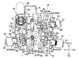
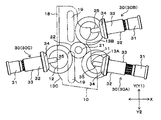
- FIGS. 1 and 2 are a perspective view and a plan view of a multi-axis drive device according to an embodiment.
- reference numeral 1 denotes a case having a recess 2 that opens upward
- 10 denotes a selector housed in the recess 2 of the case 1
- 20 denotes a motor fixed to the lower portion of the case 1.
- the opening of the recess 2 of the case 1 is covered with a cover (not shown) fixed to the case 1.
- the selector 10 is a substantially rectangular plate-like member that is long in the Y direction in FIG. 2, and two guide holes 19 extending in the Y direction are formed at the center in the width direction (X direction).
- the guide holes 19 are inserted into the guide projections 3 protruding from the bottom of the recess 2, and the selector 10 is supported by the guide holes 19 so as to be slidable in the Y direction. Yes.
- the right side surface in FIG. 2 is formed on the first cam surface 11. Further, the lower side of the left side surface is formed on the second cam surface 12, and the rack 18 in which the tooth rows are arranged in the Y direction is formed on the upper side.
- the rotating shaft 16 rotatably supported by the case 1 is provided with a pinion 17 formed so as to extend outward in the radial direction of the rotating shaft 16.
- the pinion 17 is formed along the circumferential direction of the rotating shaft 16, and both end portions in the circumferential direction of the pinion 17 are formed on the vertical wall portion 1 ⁇ / b> A as a contacted portion that forms the recess 2 in the case 1.
- the contact portion 17A is in contact.
- the pinion 17 is meshed with the rack 18.
- a dial 69 as an operation means is fixed to the rotating shaft 16. When the dial 69 is rotated, the pinion 17 is rotated, whereby the selector 10 is reciprocated in the Y direction according to the rotation direction of the dial 69 via the rack 18.
- output portions 30 are disposed on both sides of the selector 10 in the X direction so as to face the cam surfaces 11 and 12.
- the two output portions 30 (the first output portion 30A and the second output portion 30B) are separated from each other in the Y direction with respect to the first cam surface 11, and one output portion 30 is disposed with respect to the second cam surface 12.
- An output unit 30 (third output unit 30C) is provided. These output portions 30 are accommodated in an accommodating portion 60 formed in the case 1 as shown in FIGS. 1 and 2.
- Each input-side clutch member 50 has the same configuration, and includes an input gear 51 that is a spur gear and meshes with the pinion 22, and an input-side bevel gear 52 as an input-side gear that is integrally formed on the upper surface of the input gear 51.
- the input side bevel gear 52 is positioned at a predetermined position by being rotatably supported by the case 1 together with the input side clutch member 50. For example, when the motor 20 is turned ON / OFF and the rotation direction is selected by a switch provided on the dial 69 or the like, and the motor 20 is operated, all the input side clutch members 50 are rotated.
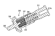
- Each output unit 30 (30A to 30C) has the same configuration, and as shown in FIGS. 4, 5A and 5B, an output shaft 31 disposed in a state facing the cam surface 11 (12), and an output An output-side clutch member 32 that can rotate integrally with the shaft 31 and can move forward and backward along the axial direction of the output shaft 31 with respect to the cam surface 11 (12), and the output-side clutch member 32 toward the input-side bevel gear 52.
- a coil spring 36 that is urged to advance.
- the output shaft 31 is rotatably supported by a support portion 61 that constitutes the housing portion 60 of the case 1.
- the output shaft 31 is a movable mechanism such as a mechanism for adjusting the height of the seat seat surface, a reclining mechanism for adjusting the angle of the seat back (backrest portion), and a mechanism for adjusting the front-rear position of the seat.
- they are connected via a torque cable (not shown).
- One end of the torque cable is inserted into a mounting hole 31 b (see FIG. 1) having a rectangular cross section formed on the rear end surface of the output shaft 31, and rotates together with the output shaft 31.
- the output-side clutch member 32 includes a cylindrical slide shaft 33 that is packaged on the selector 10 side of the output shaft 31, and a tooth surface that is integrally formed on the distal end side of the slide shaft 33.
- Output side bevel gear 34 as an output side gear toward the selector 10 side, a pin (contact portion) 35 protruding in the axial direction from the center of the output side bevel gear 34, and the slide shaft 33 urged toward the selector 10 Coil spring 36.
- the slide shaft 33 is spline-coupled to the outer peripheral surface of the output shaft 31 in the circumferential direction so that the inner peripheral surface is not rotatable relative to the outer peripheral surface, that is, can be integrally rotated, and is slidable in the axial direction. It can be moved forward and backward with respect to the cam surface.
- the coil spring 36 is housed inside the output shaft 31 and the slide shaft 33 in a compressed state, and urges the slide shaft 33 from the output shaft 31 toward the cam surface 11 (12).
- the tip of the pin 35 comes into contact with the cam surface 11 (12).
- the tip surface of the pin 35 is formed in a spherical shape, and when the selector 10 is fed in the Y direction by the dial 69, it comes into sliding contact with the cam surface 11 (12) that is abutting.
- the first cam surface 11 of the selector 10 is formed with a first recess 13A and a second recess 13B as cam portions corresponding to the first output portion 30A and the second output portion 30B.
- a third recess 13C is formed as a cam portion corresponding to the third output portion 30C.
- the housing 60 of the case 1 in which the output units 30 are housed is positioned on the rear side of the output unit 30, and the rearward movement away from the selector 10 is restricted while the output shaft 31 is rotatable.
- the output side clutch member 32 is surrounded by a pair of side wall parts 63 that are connected to the wall part 62 and are integrally formed with the support part 61 and the tip wall part 62.
- the support portion 61, the tip wall portion 62, and the pair of side wall portions 63 are formed integrally with the case 1.
- the through-hole 62a through which the pin 35 is rotatable is formed in the tip wall portion 62.
- Each output part 30 has the pin 35 penetrated through the through hole 62a of the tip wall part 62 from the upper opening in a state where the coil spring 36 is compressed and contracted so that the output side clutch member 32 and the output shaft 31 approach each other.
- the force that has been put into the housing portion 60 and then reduced is released and the output shaft 31 is inserted into the support portion 61 to be incorporated into the housing portion 60.
- the output shaft 31 is rotatably supported by the support part 61, and the pins 35 penetrate through the through holes 62a, so that both end parts are It is in a state of being rotatably supported.
- the output-side clutch member 32 urged in the direction of the selector 10 by the coil spring 36 is a clutch that has advanced in the direction of the selector 10 when the pin 35 is fitted into any one of the recesses 13A to 13C of the selector 10.
- the distal end surface of the output side bevel gear 34 abuts against the inner surface of the distal end wall portion 62, and further advancement to the selector 10 side is restricted.
- the output side bevel gear 34 meshes with the input side bevel gear 52 to be in the clutch connected state, but the front end surface of the output side bevel gear 34 abuts against the inner surface of the front end wall portion 62, thereby the axial position of the output side bevel gear 34.
- the pin 35 of the output side clutch member 32 in the first output section 30A is sent by rotating the dial 69 (rotating the rotating shaft 16 in the C1 direction) and sending the selector 10 in the Y direction. Shows a state of protruding and fitting into the first recess 13A. At this time, the output side bevel gear 34 of the first output unit 30A meshes with the input side bevel gear 52 corresponding to the first output unit 30A, and the clutch is engaged.
- the pin of the third output unit 30C 35 protrudes and fits into the third recess 13C, and the output side bevel gear 34 of the third output portion 30C meshes with the corresponding input side bevel gear 52, and the clutch is engaged.
- the pin 35 is pushed by the cam surface 11, and the output side bevel gear 34 is separated from the corresponding input side bevel gear 52, and the clutch is disengaged. It becomes.
- the selector 10 reciprocates in the Y direction by rotating the dial 69 forward and backward, and the pin 35 protrudes and fits into any one of the recesses 13A to 13C of the selector 10 during the movement, As described above, one of the first to third output units 30A to 30C is selected, and the output-side bevel gear 34 of the output unit 30 is engaged with the corresponding input-side bevel gear 52 to engage the clutch. Connected.
- the end portion (contact portion 17A) of the pinion 17 and the vertical wall portion 1A of the case 1 are provided as a restricting portion that restricts the rotation angle of the rotating shaft 16. This prevents the rack 18 and the pinion 17 from directly receiving the operating force input to the rotating shaft. As a result, in this embodiment, it is possible to prevent the rack 18 and the pinion 17 from being damaged by the operation load input from the rotary shaft 16 to the selector 10.
- each output unit 30 is housed in the housing unit 60 formed in the case 1.
- the output-side bevel gear 34 of the output-side clutch member 32 that is biased in the direction of the input-side bevel gear 52 by the coil spring 36 includes a support portion 61, a tip wall portion 62, and a pair formed integrally with the case 1.
- the distal end surface of the clutch is in contact with the distal end wall portion 62 so that the axial position is restricted and the input side bevel gear 52 is always properly engaged.
- the tip wall portion 62 is pressed by the output-side bevel gear 34 urged by the coil spring 36, and the tip wall portion 62 is integrally formed with the case 1 together with the support portion 61 and the pair of wall portions 63.
- the stress received by the pressing does not concentrate on the tip wall portion 62 but is dispersed throughout the case 1 via the support portion 61 and the pair of wall portions 63, and the deformation of the tip wall portion 62 is suppressed.
- the output side bevel gear 34 is surely positioned at a fixed position in the axial direction by contacting the tip wall portion 62.
- the input side bevel gear 52 is positioned by being supported by the case 1 together with the output side bevel gear 34, the relative positions of the two are not easily displaced. For these reasons, the backlash in the meshed state of the output side bevel gear 34 and the input side bevel gear 52 is always stable with high accuracy. As a result, it is possible to obtain an effect that the output-side bevel gear 34 is prevented from per-contacting the input-side bevel gear 52 and durability is improved, and an operating sound generated at the time of meshing is reduced.
- the selector 10 of the present invention is linearly moved.
- the selector 10 is a disk-shaped rotating member, and its peripheral surface is a cam surface. It can change into the form arrange
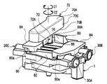
- the dial 70 is fixed to the end of the rotary shaft 16 and a part of the dial 70 abuts a part of the case 1, thereby It is characterized in that the rotation angle is regulated.
- the dial 70 as the operation means is a long component whose longitudinal direction is a direction orthogonal to the axial direction of the rotary shaft 16.
- the dial 70 includes an upper wall portion 70A and a lower wall portion 70B that extend in a direction substantially orthogonal to the axial direction of the rotary shaft 16, and a side wall that connects the upper wall portion 70A and the lower wall portion 70B. 70C is provided.
- a fixing hole (not shown) formed along the shape of the end of the rotating shaft 16 is formed in the lower wall portion 70B. The end of the rotating shaft 16 is inserted into the fixing hole and a screw (not shown) is used to fix the dial 70 to the end of the rotating shaft 16.
- the lower wall portion 70B is provided with a protrusion 72 as a contact portion formed in a substantially cubic shape.
- the protrusion 72 is disposed at a portion adjacent to a fixing hole provided in the lower wall portion 70B.
- the protrusion 72 is configured to rotate and move about the rotation shaft 16 as an axis.
- the surfaces of the protrusion 72 that are directed in the circumferential direction of the rotating shaft 16 are a first contact surface 72A and a second contact surface 72B.
- the cover 80 includes a base 82 that covers the recess 2 of the case 1 (see FIG. 2).
- the cover 80 includes a convex portion 84 that is formed so as to protrude from the base portion 82 in the axial direction of the motor shaft 21 (see FIG. 2) and covers the housing portion 60 (see FIG. 2).
- the base 82 is formed with an insertion hole 86 through which the rotary shaft 16 is inserted. Further, the base 82 is provided with a first protrusion 88 and a second protrusion 90 as contacted parts formed so as to protrude in the plate thickness direction of the base 82.
- the first projecting portion 88 and the second projecting portion 90 are formed in a substantially rectangular parallelepiped shape, and are disposed at a portion adjacent to the insertion hole 86.
- the surfaces of the first protrusion 88 and the second protrusion 90 facing the insertion hole 86 are the first contact surfaces where the first contact surface 72A and the second contact surface 72B of the protrusion 72 are in contact.
- a contact surface 88A and a second contacted surface 90A are provided.
- a mounting hole 80a is formed in the base portion 82, and a screw is inserted into the mounting hole 80a, and the screw is tightened into a mounting hole 1b (see FIG. 2) formed in the case 1.
- the cover 80 is fixed to the case 1. It is assumed that the cover 80 forms a part of the case 1 in a state where the cover 80 is fixed to the case 1.
Landscapes
- Engineering & Computer Science (AREA)
- General Engineering & Computer Science (AREA)
- Mechanical Engineering (AREA)
- Aviation & Aerospace Engineering (AREA)
- Transportation (AREA)
- Gear Transmission (AREA)
- Transmission Devices (AREA)
- Seats For Vehicles (AREA)
Abstract
Description
図1および図2は、一実施形態に係る多軸駆動装置の斜視図および平面図である。これら図で符号1は上方に開口する凹所2を有するケース、10はケース1の凹所2内に収容されたセレクタ、20はケース1の下部に固定されたモータである。ケース1の凹所2の開口は、ケース1に固定される図示せぬカバーによって覆われる。セレクタ10は図2においてY方向に長い略長方形状の板状部材であって、幅方向(X方向)の中央部にはY方向に延びる2つのガイド孔19が形成されている。これらガイド孔19には、凹所2の底部から突出するガイド突起3がそれぞれ挿入されており、セレクタ10はガイド孔19がガイド突起3にガイドされることによりY方向にスライド自在に支持されている。
次に、上記多軸駆動装置の作用を説明する。
図2および図4は、上記ダイヤル69を回転させて(回転軸16をC1方向に回転させて)セレクタ10をY方向に送ることにより、第1出力部30Aにおける出力側クラッチ部材32のピン35が第1凹部13Aに突出して嵌り込んだ状態を示している。この時、第1出力部30Aの出力側ベベルギヤ34は、第1出力部30Aに対応する入力側ベベルギヤ52に噛み合い、クラッチ接続の状態となる。一方、他の出力部30(第2出力部30と第3出力部30)においてはピン35がカム面11,12に押されて出力側ベベルギヤ34は対応する入力側ベベルギヤ52から離れている。また、この状態において、回転軸16に設けられたピニオン17の端部(当接部17A)はケース1の縦壁部1Aに当接している。そのため、回転軸16をC1方向へ、それ以上回転させることが規制される。
次に図7A及び図7Bを用いて、上記実施形態の変形例について説明する。
なお、上記実施形態と同一に部材については同一の符号を付してその説明を省略する。
モータ20の動力を伝える出力部30(30A、30B、30C)を選択するために、ダイヤル70を矢印C2方向に回転させると、ダイヤル70に設けられた突起部72の第1当接面72Aがカバー80に設けられた第1突起部88の第1被当接面88Aに接触する。そのため、ダイヤル70を矢印C2方向へそれ以上回転させることが規制される。また、ダイヤル70を矢印C1方向に回転させると、ダイヤル70に設けられた突起部72の第2当接面72Bがカバー80に設けられた第2突起部90の第2被当接面90Aに接触する。そのため、ダイヤル70を矢印C1方向へそれ以上回転させることが規制される。その結果、本実施形態では、ダイヤル70から回転軸16を通じてセレクタ10に入力される操作荷重によって、ラック18及びピニオン17が破損することを防止することができる。
Claims (3)
- ケースに固定されると共に、車両に搭載された複数の可動機構を駆動する単一のモータと、
前記ケースの内部に設けられると共に、前記モータの動力が伝達される入力側ギヤと、
前記入力側ギヤに対して進退可能に設けられることによって、前記入力側ギヤに選択的に噛み合わされ、前記入力側ベベルギヤから伝達された動力を前記可動機構に伝達する出力側ギヤと、
ラックを備えることによって一の方向及びこれと反対方向にスライド可能とされると共に、前記出力側ギヤの一部を押圧することによって前記出力側ギヤを後退させ、前記出力側ギヤと前記入力側ギヤとの噛み合わせを断接させるセレクタと、
前記セレクタに設けられた前記ラックと噛み合わされるピニオンを備えると共に、操作手段に入力された操作力によって軸線まわりに回転することによって前記セレクタをスライドさせる回転軸と、
前記回転軸を含む前記操作手段側に設けられ、前記回転軸の回転角度を規制する規制部と、
を備えた多軸駆動装置。 - 前記規制部は、前記回転軸に固定された操作手段と、前記ケースに設けられると共に前記操作手段の一部が当接する被当接部と、を含んで構成された請求項1記載の多軸駆動装置。
- 前記規制部は、前記ケースの内部に設けられると共に前記回転軸の一部に形成された当接部と、前記ケースに設けられると共に前記当接部が当接する被当接部と、を含んで構成された請求項1記載の多軸駆動装置。
Priority Applications (5)
| Application Number | Priority Date | Filing Date | Title |
|---|---|---|---|
| EP12752273.8A EP2682641A4 (en) | 2011-02-28 | 2012-01-24 | Multi-shaft drive device |
| JP2013502212A JP5797734B2 (ja) | 2011-02-28 | 2012-01-24 | 多軸駆動装置 |
| KR1020137025517A KR101825774B1 (ko) | 2011-02-28 | 2012-01-24 | 다축 구동 장치 |
| CN201280010504.0A CN103384782B (zh) | 2011-02-28 | 2012-01-24 | 多轴驱动装置 |
| US14/001,671 US9267589B2 (en) | 2011-02-28 | 2012-01-24 | Multi-shaft drive device |
Applications Claiming Priority (2)
| Application Number | Priority Date | Filing Date | Title |
|---|---|---|---|
| JP2011-042118 | 2011-02-28 | ||
| JP2011042118 | 2011-02-28 |
Publications (1)
| Publication Number | Publication Date |
|---|---|
| WO2012117771A1 true WO2012117771A1 (ja) | 2012-09-07 |
Family
ID=46757713
Family Applications (1)
| Application Number | Title | Priority Date | Filing Date |
|---|---|---|---|
| PCT/JP2012/051458 Ceased WO2012117771A1 (ja) | 2011-02-28 | 2012-01-24 | 多軸駆動装置 |
Country Status (6)
| Country | Link |
|---|---|
| US (1) | US9267589B2 (ja) |
| EP (1) | EP2682641A4 (ja) |
| JP (1) | JP5797734B2 (ja) |
| KR (1) | KR101825774B1 (ja) |
| CN (1) | CN103384782B (ja) |
| WO (1) | WO2012117771A1 (ja) |
Cited By (1)
| Publication number | Priority date | Publication date | Assignee | Title |
|---|---|---|---|---|
| JP2018189139A (ja) * | 2017-05-01 | 2018-11-29 | 周浩 李 | 伝動装置及び方法 |
Families Citing this family (8)
| Publication number | Priority date | Publication date | Assignee | Title |
|---|---|---|---|---|
| CZ306544B6 (cs) * | 2016-01-03 | 2017-03-01 | České vysoké učení technické v Praze, Fakulta strojní, Ústav výrobních strojů a zařízení | Pohon potahových řemenů zejména vertikálního balicího stroje |
| JP6720829B2 (ja) | 2016-10-26 | 2020-07-08 | トヨタ紡織株式会社 | シート駆動装置 |
| JP6753320B2 (ja) * | 2017-01-19 | 2020-09-09 | トヨタ紡織株式会社 | シート駆動装置 |
| US10738866B2 (en) * | 2018-04-19 | 2020-08-11 | Robert Bosch Mexico Sistemas Automotrices S.A. de C.V. | Modular actuator for providing relative motion between two points |
| US11602337B2 (en) | 2019-04-24 | 2023-03-14 | Nuvasive, Inc. | Transmission assembly |
| CN110081132A (zh) * | 2019-05-30 | 2019-08-02 | 新乡北方车辆仪表有限公司 | 一种三路输出分动箱 |
| JP7337964B2 (ja) | 2019-06-18 | 2023-09-04 | ニューヴェイジヴ,インコーポレイテッド | 組織牽引システム |
| US11547395B2 (en) | 2019-06-18 | 2023-01-10 | Nuvasive, Inc. | Tissue retraction system |
Citations (5)
| Publication number | Priority date | Publication date | Assignee | Title |
|---|---|---|---|---|
| JPS5028181U (ja) * | 1973-07-10 | 1975-04-01 | ||
| JPS52164671U (ja) * | 1976-06-09 | 1977-12-13 | ||
| JPH06156123A (ja) | 1992-11-25 | 1994-06-03 | Mitsuba Electric Mfg Co Ltd | 車両用パワーシートにおける可動部駆動装置 |
| JP2005145308A (ja) * | 2003-11-17 | 2005-06-09 | Kiyotaka Hyodo | 船外機 |
| JP2011021679A (ja) * | 2009-07-15 | 2011-02-03 | Nhk Spring Co Ltd | クラッチ装置 |
Family Cites Families (10)
| Publication number | Priority date | Publication date | Assignee | Title |
|---|---|---|---|---|
| US2674182A (en) * | 1950-06-22 | 1954-04-06 | Joseph W Kirkpatrick | Fruit juice extractor |
| US2845807A (en) * | 1953-08-10 | 1958-08-05 | Hoe & Co R | Reversing drive |
| JPS5441898A (en) * | 1977-09-06 | 1979-04-03 | Mitsubishi Chem Ind Ltd | Purification of stevioside |
| DE2901208C2 (de) * | 1979-01-13 | 1984-08-09 | Keiper Automobiltechnik Gmbh & Co Kg, 5630 Remscheid | Verstellbarer Sitz, insbesondere Fahrzeugsitz |
| US5009296A (en) * | 1986-12-24 | 1991-04-23 | Tokyo Seat Co., Ltd. | Power transmitting apparatus for use in vehicle |
| SE464287B (sv) * | 1987-10-12 | 1991-04-08 | Haakansson Bengt E W | Anordning foer att reglera objekt i foerarmiljoen i ett fordon |
| US6050641A (en) | 1996-12-20 | 2000-04-18 | Schukra Of North America, Ltd. | Four-way power lumbar system |
| JP4275039B2 (ja) * | 2003-11-10 | 2009-06-10 | 株式会社ミツバ | 減速機構付モータ及び減速機構付パワーシートモータ |
| JP4313280B2 (ja) * | 2003-11-28 | 2009-08-12 | アスモ株式会社 | シート駆動用モータおよびパワーシート装置 |
| JP2011031733A (ja) * | 2009-07-31 | 2011-02-17 | Imasen Electric Ind Co Ltd | 車両用電動シートのリクライニング駆動装置 |
-
2012
- 2012-01-24 JP JP2013502212A patent/JP5797734B2/ja active Active
- 2012-01-24 CN CN201280010504.0A patent/CN103384782B/zh not_active Expired - Fee Related
- 2012-01-24 KR KR1020137025517A patent/KR101825774B1/ko not_active Expired - Fee Related
- 2012-01-24 US US14/001,671 patent/US9267589B2/en active Active
- 2012-01-24 EP EP12752273.8A patent/EP2682641A4/en not_active Withdrawn
- 2012-01-24 WO PCT/JP2012/051458 patent/WO2012117771A1/ja not_active Ceased
Patent Citations (5)
| Publication number | Priority date | Publication date | Assignee | Title |
|---|---|---|---|---|
| JPS5028181U (ja) * | 1973-07-10 | 1975-04-01 | ||
| JPS52164671U (ja) * | 1976-06-09 | 1977-12-13 | ||
| JPH06156123A (ja) | 1992-11-25 | 1994-06-03 | Mitsuba Electric Mfg Co Ltd | 車両用パワーシートにおける可動部駆動装置 |
| JP2005145308A (ja) * | 2003-11-17 | 2005-06-09 | Kiyotaka Hyodo | 船外機 |
| JP2011021679A (ja) * | 2009-07-15 | 2011-02-03 | Nhk Spring Co Ltd | クラッチ装置 |
Non-Patent Citations (1)
| Title |
|---|
| See also references of EP2682641A4 * |
Cited By (1)
| Publication number | Priority date | Publication date | Assignee | Title |
|---|---|---|---|---|
| JP2018189139A (ja) * | 2017-05-01 | 2018-11-29 | 周浩 李 | 伝動装置及び方法 |
Also Published As
| Publication number | Publication date |
|---|---|
| US9267589B2 (en) | 2016-02-23 |
| CN103384782B (zh) | 2016-01-20 |
| EP2682641A1 (en) | 2014-01-08 |
| CN103384782A (zh) | 2013-11-06 |
| KR101825774B1 (ko) | 2018-02-05 |
| EP2682641A4 (en) | 2017-06-28 |
| EP2682641A8 (en) | 2014-03-12 |
| JP5797734B2 (ja) | 2015-10-21 |
| KR20140010108A (ko) | 2014-01-23 |
| JPWO2012117771A1 (ja) | 2014-07-07 |
| US20130327181A1 (en) | 2013-12-12 |
Similar Documents
| Publication | Publication Date | Title |
|---|---|---|
| JP5797734B2 (ja) | 多軸駆動装置 | |
| KR101498401B1 (ko) | 동력 전달 기구 및 이것을 이용한 다축 구동 장치 | |
| US9027442B2 (en) | Multi-shaft drive device | |
| JP5934694B2 (ja) | 多軸駆動装置 | |
| JP5873806B2 (ja) | 出力部材及び多軸駆動装置 | |
| JP5820872B2 (ja) | 多軸駆動装置 | |
| JP2012177459A (ja) | 多軸駆動装置 | |
| JP2012177460A (ja) | ベベルギヤ、動力伝達機構および多軸駆動装置 | |
| JP2012180850A (ja) | 動力伝達機構および多軸駆動装置 | |
| JP2012180852A (ja) | 多軸駆動装置 | |
| JP2012176734A (ja) | 多軸駆動装置 | |
| JP2023073841A (ja) | 多軸駆動装置及びパワーシート | |
| WO2011007791A1 (ja) | クラッチ装置 | |
| JP2012180848A (ja) | 複合ギヤの支持構造 | |
| JP2012180851A (ja) | ウォームギヤの支持構造 |
Legal Events
| Date | Code | Title | Description |
|---|---|---|---|
| 121 | Ep: the epo has been informed by wipo that ep was designated in this application |
Ref document number: 12752273 Country of ref document: EP Kind code of ref document: A1 |
|
| ENP | Entry into the national phase |
Ref document number: 2013502212 Country of ref document: JP Kind code of ref document: A |
|
| WWE | Wipo information: entry into national phase |
Ref document number: 14001671 Country of ref document: US |
|
| NENP | Non-entry into the national phase |
Ref country code: DE |
|
| ENP | Entry into the national phase |
Ref document number: 20137025517 Country of ref document: KR Kind code of ref document: A |