WO2012117799A1 - Terminal d'informations, serveur, et procédé et programme de détermination de destinations de connexion - Google Patents
Terminal d'informations, serveur, et procédé et programme de détermination de destinations de connexion Download PDFInfo
- Publication number
- WO2012117799A1 WO2012117799A1 PCT/JP2012/052352 JP2012052352W WO2012117799A1 WO 2012117799 A1 WO2012117799 A1 WO 2012117799A1 JP 2012052352 W JP2012052352 W JP 2012052352W WO 2012117799 A1 WO2012117799 A1 WO 2012117799A1
- Authority
- WO
- WIPO (PCT)
- Prior art keywords
- information
- information terminal
- terminal
- connection destination
- application
- Prior art date
- Legal status (The legal status is an assumption and is not a legal conclusion. Google has not performed a legal analysis and makes no representation as to the accuracy of the status listed.)
- Ceased
Links
Images





Classifications
-
- G—PHYSICS
- G10—MUSICAL INSTRUMENTS; ACOUSTICS
- G10H—ELECTROPHONIC MUSICAL INSTRUMENTS; INSTRUMENTS IN WHICH THE TONES ARE GENERATED BY ELECTROMECHANICAL MEANS OR ELECTRONIC GENERATORS, OR IN WHICH THE TONES ARE SYNTHESISED FROM A DATA STORE
- G10H1/00—Details of electrophonic musical instruments
- G10H1/36—Accompaniment arrangements
- G10H1/361—Recording/reproducing of accompaniment for use with an external source, e.g. karaoke systems
- G10H1/365—Recording/reproducing of accompaniment for use with an external source, e.g. karaoke systems the accompaniment information being stored on a host computer and transmitted to a reproducing terminal by means of a network, e.g. public telephone lines
-
- G—PHYSICS
- G10—MUSICAL INSTRUMENTS; ACOUSTICS
- G10H—ELECTROPHONIC MUSICAL INSTRUMENTS; INSTRUMENTS IN WHICH THE TONES ARE GENERATED BY ELECTROMECHANICAL MEANS OR ELECTRONIC GENERATORS, OR IN WHICH THE TONES ARE SYNTHESISED FROM A DATA STORE
- G10H1/00—Details of electrophonic musical instruments
- G10H1/0033—Recording/reproducing or transmission of music for electrophonic musical instruments
- G10H1/0083—Recording/reproducing or transmission of music for electrophonic musical instruments using wireless transmission, e.g. radio, light, infrared
Definitions
- the present invention relates to an information terminal that can be connected to an external device wirelessly, a server that can communicate with the information terminal, a connection destination determination method in an information processing apparatus, and a program.
- the current communication karaoke system generally includes a server, a commander (karaoke device), peripheral devices such as an audio device, a display, a microphone, and a remote controller having an instruction function for the commander.
- the server has a music distribution function and the like.
- the commander has a performance function for the delivered music.
- equipment (commander, peripheral device, and remote controller) other than a server is usually installed in each room with an equivalent configuration. Therefore, in order to prevent interference between the equipment in one room and the equipment in another room, it is necessary to associate the equipment in the same room with each other.
- the remote controller transmits a remote control identification number to the commander by infrared communication, and the commander transmits a commander identification signal by radio communication using radio waves as a medium to the remote control.
- a method of matching is disclosed.
- the current online karaoke system is based on the premise that karaoke services are provided mainly by Commander.
- karaoke services are provided mainly by Commander.
- the future karaoke system will change to a new configuration that does not require a commander or remote control.
- an information terminal carried by the user is used as a hub device.
- the information terminal and the peripheral device are dynamically and wirelessly connected when using the service.
- the user wirelessly connects the user's information terminal and a peripheral device of karaoke.
- a user uses various karaoke services, acquiring a desired application and content to an information terminal on demand from a server.
- the present invention relates to an information terminal capable of dynamically establishing a connection state with an appropriate peripheral device according to an application to be used, a server capable of communicating with the information terminal, a connection destination determination method in an information processing apparatus, and The purpose is to provide a program.
- the information terminal is an information terminal that can be connected to an external device wirelessly, and includes position information acquisition means, device determination means, first connection destination determination means, and connection establishment means.
- the position information acquisition unit acquires terminal position information which is information indicating the position of the information terminal.
- the device determination unit determines a device to be used, which is a peripheral device used in a startup application that is an application started on the information terminal.
- the first connection destination determination unit refers to the first storage unit, and connects a peripheral device that is suitable for the device in use and installed at a position indicated by the terminal position information to the information terminal by the radio It is determined as the connection destination device that establishes the state.
- the first storage means stores information indicating peripheral devices installed at a plurality of positions and position information indicating the plurality of positions in association with each other.
- the connection establishment unit establishes a wireless connection state with the connection destination device.
- the information terminal refers to the first storage means based on the acquired terminal position information. Then, the information terminal determines, as a connection destination device, a peripheral device that is compatible with the device used by the activation application and is installed at the position where the information terminal exists.
- the information terminal can establish a wireless connection state with the connection destination device. That is, the information terminal can dynamically establish a connection state with an appropriate peripheral device installed at a position where the information terminal exists in accordance with the activation application.
- the information terminal may further include an application determining unit that determines a specified application as the activation application among a plurality of applications operable on the information terminal.
- the device determination unit refers to a second storage unit that stores information indicating the plurality of applications in association with information indicating at least one peripheral device used in the plurality of applications. Then, the information terminal may determine at least one device used corresponding to the activation application.
- the first connection destination determination means establishes a wireless connection state between the information terminal and the peripheral device that is adapted to the at least one device in use and is installed at a position indicated by the terminal position information. The connection destination device may be determined.
- the user of the information terminal can connect the information terminal to an appropriate peripheral device corresponding to the desired application by designating the desired application among the plurality of applications.
- the activation application may have at least a function for reproducing a sound of a song used in karaoke and an image corresponding to the song.
- the said device determination means may determine the music output apparatus and display apparatus which are peripheral devices which reproduce
- the information terminal establishes a connection state with these devices if the music output device and the display device are installed at the position where the information terminal exists at that time in accordance with the activation application used for karaoke. can do.
- the information terminal causes the connection destination device to output at least one of the sound and the image by the function of the activation application after a connection state with the connection destination device is established by the connection establishment unit. Means may further be provided.
- the information terminal can cause the display device and the music output device established with the information terminal to output the sound of the music and the image corresponding to the music. Therefore, the user can perform karaoke using the display device and the music output device.
- the information terminal may further include a billing determining unit that determines a billing amount for the user of the information terminal according to an attribute of the connection destination device whose connection state has been established by the connection establishing unit. In this case, the information terminal can determine an appropriate charge amount for the use of the connection destination device whose connection state has been established with the information terminal according to the activation application.
- the second storage means associates information specifying a plurality of rooms of a karaoke facility with information indicating peripheral devices installed in the plurality of rooms as the position information and the information indicating the peripheral devices. You may remember.
- Karaoke facilities usually have multiple rooms, and the same peripheral devices are often installed in each room. In such a case, the information terminal can dynamically establish a connection state with an appropriate peripheral device installed in a room where the information terminal exists. Therefore, the information terminal does not malfunction the same peripheral device installed in another room.
- the information terminal is an information terminal that can be connected to an external device wirelessly, and includes position information acquisition means, device determination means, first transmission means, first reception means, Two connection destination determination means and connection establishment means are provided.
- the position information acquisition unit acquires terminal position information which is information indicating the position of the information terminal.
- the device determination unit determines a device to be used, which is a peripheral device used in a startup application that is an application started on the information terminal.
- the first transmission means transmits the terminal location information to a server connected to the information terminal.
- the first receiving unit is configured to receive information indicating a peripheral device installed at a position indicated by the terminal location information, determined by the server based on the terminal location information transmitted by the first transmission unit. Receive from.
- the second connection destination determination unit determines the peripheral device that is compatible with the device in use as a connection destination device. .
- the connection establishment unit establishes a wireless connection state with the connection destination device.
- the information terminal acquires information indicating the peripheral device installed at the position where the information terminal exists from the server.
- the information terminal determines the compatible peripheral device as the connection destination device.
- the information terminal can establish a wireless connection state with the connection destination device. That is, the information terminal can dynamically establish a connection state with an appropriate peripheral device installed at a position where the information terminal exists in accordance with the activation application.
- An information terminal is an information terminal that can be connected to an external device wirelessly, and includes position information acquisition means, second transmission means, second reception means, and third connection destination determination means. And connection establishment means.
- the position information acquisition unit acquires terminal position information which is information indicating the position of the information terminal.
- the second transmission means transmits activation application information, which is information indicating an activation application that is an application activated on the information terminal, to a server connected to the information terminal.
- the second receiving unit is configured to receive information indicating a used device, which is a peripheral device used in the activated application, determined by the server based on the activated application information transmitted by the second transmitting unit. Receive from.
- the third connection destination determination means is installed at a position indicated by the terminal position information that matches the use device indicated by the information received by the second reception means with reference to the first storage means.
- the selected peripheral device is determined as a connection destination device.
- the first storage means stores information indicating peripheral devices installed at a plurality of positions and position information indicating the plurality of positions in association with each other.
- the connection establishment unit establishes a wireless connection state with the connection destination device.
- the information terminal acquires information indicating the device used in the startup application from the server. Then, the information terminal refers to the first storage unit based on the acquired terminal position information, and determines the peripheral device that is suitable for the device used and installed at the position where the information terminal exists as the connection destination device. To do.
- the information terminal can establish a wireless connection state with the connection destination device. That is, the information terminal can dynamically establish a connection state with an appropriate peripheral device installed at a position where the information terminal exists in accordance with the activation application.
- the fourth server of the present invention includes terminal information acquisition means, device determination means, fourth connection destination determination means, and connection destination notification means.
- the terminal information acquisition unit acquires terminal position information, which is information indicating the position of the information terminal, from an information terminal that can be connected to an external device wirelessly.
- the device determination unit determines a device to be used, which is a peripheral device used in a startup application that is an application started on the information terminal.
- the fourth connection destination determination means refers to the first storage means, and connects the peripheral device that is suitable for the device in use and installed at the position indicated by the terminal position information to the information terminal by the wireless communication. It is determined as a connection destination device for establishing the state.
- the first storage means stores information indicating peripheral devices installed at a plurality of positions and position information indicating the plurality of positions in association with each other.
- the connection destination notifying unit transmits information on the connection destination device determined by the fourth connection destination determining unit to the information terminal.
- the server acquires terminal location information indicating the location of the information terminal from the information terminal. Then, when the peripheral device installed at the position where the information terminal exists matches the device used by the activation application, the information terminal determines this as a connection destination device and transmits information on the connection destination device to the information terminal. Can do. Therefore, the information terminal that has received this information can dynamically establish a connection state with an appropriate peripheral device installed at a position where the information terminal exists, according to the activation application.
- the fifth connection destination determination method of the present invention is a connection destination determination method processed in the information processing apparatus, and includes a position information acquisition step, a device determination step, and a first connection destination determination step.
- position information acquisition step terminal position information, which is information indicating the position of an information terminal that can be connected to an external device wirelessly, is acquired.
- device determination step a device to be used that is a peripheral device used in a startup application that is an application to be started on the information terminal is determined.
- the first connection destination determination step referring to the first storage means, a peripheral device that matches the device in use and is installed at a position indicated by the terminal position information is connected to the information terminal by the wireless communication. It is determined as a connection destination device for establishing the state.
- the first storage means stores information indicating peripheral devices installed at a plurality of positions and position information indicating the plurality of positions in association with each other.
- connection destination determination method is processed in the information processing apparatus, and based on the terminal position information, the first storage means is referred to, and it is installed at the position where the information terminal exists and matches the device used by the activation application.
- the peripheral device thus determined is determined as the connection destination device. Therefore, if the information terminal establishes a wireless connection state with the connection destination device determined by this method, the information terminal is connected to an appropriate peripheral installed at the position where the information terminal exists according to the activation application.
- a connection state can be dynamically established with the device.
- the sixth program of the present invention includes an instruction for causing a computer of an information terminal that can be connected to an external device wirelessly to execute a position information acquisition step, a device determination step, and a first connection destination determination step.
- position information acquisition step terminal position information that is information indicating the position of the information terminal is acquired.
- device determination step a device to be used that is a peripheral device used in a startup application that is an application to be started on the information terminal is determined.
- the first connection destination determination step referring to the first storage means, a peripheral device that matches the device in use and is installed at a position indicated by the terminal position information is connected to the information terminal by the wireless communication. It is determined as a connection destination device for establishing the state.
- the first storage means stores information indicating peripheral devices installed at a plurality of positions and position information indicating the plurality of positions in association with each other.
- the first storage means When an instruction of the program is executed by the computer of the information terminal, the first storage means is referred to based on the terminal position information, and it is installed at the position where the information terminal exists and is compatible with the device used by the activation application.
- the peripheral device is determined as the connection destination device. Therefore, if the information terminal establishes a wireless connection state with the connection destination device determined in this way, the information terminal can be appropriately installed at a position where the information terminal exists according to the activation application.
- a connection state can be dynamically established with a peripheral device.
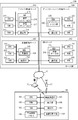
- FIG. 2 is a block diagram illustrating configurations of an information terminal 100 and a server group 200.
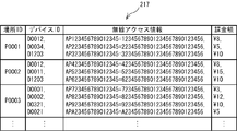
- FIG. It is explanatory drawing of a structure of use device DB216. It is explanatory drawing of a structure of installation device DB217.
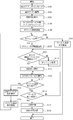
- 3 is a flowchart of processing of the first embodiment executed by the information terminal 100.
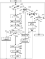
- 6 is a flowchart of processing of the second embodiment executed by the information terminal 100.
- 12 is a flowchart of processing of the second embodiment executed by the device management server 210.
- FIG. 12 is a flowchart of processing of the third embodiment executed by the device management server 210. It is a flowchart of the process of 4th embodiment performed with the information terminal 100.
- FIG. 14 is a flowchart of processing of a fourth embodiment executed by the device management server 210.
- the karaoke system 1 includes a server group 200, an information terminal 100, and peripheral devices such as an audio device 71.
- the server group 200 is deployed in the karaoke service center 2 built on the cloud system.
- the server group 200 is connected to the network 10 (for example, the Internet) via the router 11.
- the server group 200 stores applications and data used in the karaoke service, and provides them in response to a request from an external device such as the information terminal 100.
- the server group 200 of this embodiment includes four servers: a device management server 210, an application distribution server (hereinafter referred to as an application distribution server) 220, a music distribution server 230, and a social network service server (hereinafter referred to as an SNS server) 240. It is configured.
- the device management server 210 manages a management function of peripheral devices mainly used in the karaoke service.
- the application distribution server 220 mainly has a function of distributing applications to external devices such as the information terminal 100.
- the music distribution server 230 mainly has a function of distributing music data to an external device such as the information terminal 100.
- the SNS server 240 mainly has a function of sharing post data transmitted from the information terminal 100 with other information terminals 100. Details of the configuration of each server will be described later.
- the information terminal 100 is an information processing apparatus having a proximity wireless communication function and a wide area wireless communication function.
- the information terminal 100 according to the present embodiment is a terminal device that can be carried by a user. Accordingly, the user can bring the information terminal 100 used by the user into, for example, a karaoke-only store (so-called karaoke box) 3 or a restaurant 4 such as a snack equipped with karaoke equipment.
- a plurality of rooms 30 having the same configuration are prepared in the store 3.
- Each room 30 is provided with an acoustic device 71, a microphone 72, a display 73, and a camera 74, which are four types of peripheral devices that can be used in various karaoke services.
- the acoustic device 71 is a device that reproduces the sound of music, and includes a MIDI data reproduction unit, an amplifier, and a speaker.
- the microphone 72 is a device that acquires peripheral sounds. Particularly in karaoke, the microphone 72 is used to acquire the voice data of the singer.
- the display 73 is a device that reproduces and displays an image corresponding to a song, such as a song lyrics telop and a background video.
- the camera 74 is a device that can capture a moving image. For example, the camera 74 is used to shoot a movie of a singer who is singing.
- all of these peripheral devices include a wireless communication unit (not shown) and have a proximity wireless communication function. Therefore, the information terminal 100 can be connected by proximity wireless communication.
- Each room 30 is provided with a wireless access point (hereinafter referred to as wireless AP) 13.
- the wireless AP 13 in each room 30 is connected to the network 10 via the switch 12 and the router 11. Therefore, the information terminal 100 can connect to the network 10 by connecting to the wireless AP 13 by proximity wireless communication.
- each room 30 is provided with a non-contact type IC tag 80 in which at least information for specifying the position of each room 30 is stored.
- the IC tag 80 may be attached to the wall of the room 30 together with a message for prompting information reading.
- the IC tag 80 is used for the information terminal 100 to acquire position information.
- an acoustic device 71, a microphone 72, and a display 73 are installed in the restaurant 4.
- a camera 74 may be installed in addition to these peripheral devices.
- the restaurant 4 may not be provided with the router 11 or the wireless AP 13. Even in such a case, the information terminal 100 can be connected to the network 10 by directly connecting to the radio base station 5 by wide area radio. Details of the configuration of the information terminal 100 will be described later.
- the number of the above-mentioned store 3, its room 30, and the restaurant 4 is not restricted to the number illustrated by FIG. Moreover, the names of the store 3 and the restaurant 4 are merely used for convenience, and the store 3 and the restaurant 4 are in the same position as karaoke facilities where peripheral devices used in various karaoke services are installed.
- the user uses the karaoke service at the store 3 as follows, for example.
- the user brings his / her information terminal 100 into the room 30 of a certain store 3.
- the user connects the information terminal 100 to the server group 200 and downloads necessary applications and data according to the karaoke service that the user wants to use.
- the information terminal 100 reads information indicating the position of the room 30 from the IC tag 80 provided in the room 30 as the position information of the information terminal 100.
- peripheral devices for example, the audio equipment 71, the microphone 72, and the display 73
- the peripheral device operates in accordance with instructions and data transmitted from the information terminal 100.
- the karaoke system 1 does not use a commander or a remote control that is usually prepared for each room at a conventional karaoke facility. Instead, the information terminal 100 brought in by the user is used as a hub device, and the information terminal 100 and necessary peripheral devices are dynamically associated and connected according to the karaoke service to be used. . Details of processing in the information terminal 100 when using the karaoke service will be described later.
- each server included in the server group 200 will be described below with reference to FIGS.
- illustration of the router 11 and the switch 12 shown in FIG. 1 is omitted for simplification of description.
- the device management server 210, the application distribution server 220, the music distribution server 230, and the SNS server 240 (hereinafter collectively referred to simply as servers 210 to 240) included in the server group 200 are stored.
- the basic configuration is the same except that information stored in hard disk devices (hereinafter referred to as HDDs) 215, 225, 235, and 245, which are the devices, is different.
- the servers 210 to 240 include CPUs 211, 221, 231, 241, ROMs 212, 222, 232, 242, RAMs 213, 223, 233, 243, and communication units 214, 224, 234, 244, respectively. including.
- the CPUs 211, 221, 231, and 241 read various programs stored in the ROMs 212, 222, 232, and 242 or the HDDs 215, 225, 235, and 245, respectively, and execute various processes according to the instructions.
- the HDD 215 of the device management server 210 will be described.
- the HDD 215 stores a used device database (hereinafter referred to as DB) 216 and an installed device DB 217.
- the HDD 215 stores programs for various processes executed by the device management server 210.
- the CPU 211 of the device management server 210 transmits data stored in these databases to the information terminal 100 and performs various processes using these databases.
- the use device DB 216 stores an application ID and at least one device ID corresponding to each application ID for a plurality of applications operable on the information terminal 100.
- Application ID is information for identifying each application.
- an application that can be operated on the information terminal 100, for example, a basic service of karaoke “a service that outputs a sound acquired by a microphone together with a sound and an image of a song, and an additional service“ a state of singing ”
- An application that provides “a service for photographing and providing the moving image to the SNS” or the like.
- the service for outputting the sound acquired by the microphone is referred to as a music reproduction service.
- a service for photographing the state of singing and providing the moving image to the SNS is hereinafter referred to as a moving image photographing service.
- an application ID such as“ S0001 ”or“ S0002 ”is unique. The identification code is assigned.
- Device ID is information for identifying each peripheral device.
- peripheral devices used in the karaoke service for example, there are an acoustic device 71, a microphone 72, a display 73, and a camera 74.
- a unique identification code such as “D0011” or “S0012” is assigned to each of these peripheral devices as a device ID.
- the acoustic device 71, the microphone 72, and the display 73 are necessary to provide the “music reproduction service”.
- at least a microphone 72 and a camera 74 are required. Therefore, in the used device DB 216, device IDs of necessary peripheral devices are associated with application IDs of applications that provide each service.
- the application ID only needs to be associated with the device ID of at least one peripheral device used in the application.
- a location ID is associated with at least one device ID corresponding to each location ID. Further, the installed device DB 217 stores the wireless access information corresponding to each device ID and the charge amount corresponding to each device ID in association with the device ID.
- the location ID is information for identifying each location.
- a store 3 and a restaurant 4 (see FIG. 1) that are karaoke facilities are assumed as a plurality of places. Therefore, a unique identification code such as “P0001” or “P0002” is assigned to each of these stores 3 and restaurants 4 as a place ID.
- a location ID is assigned to each room 30.
- Wireless access information is information necessary when the information terminal 100 connects to a peripheral device wirelessly.
- the wireless access information of this embodiment includes a wireless identification ID and an authentication code of peripheral devices.
- the information terminal 100 can generate a wireless session with a peripheral device by acquiring the wireless access information.
- the same periphery installed in another room 30 can be managed by distinguishing and managing the wireless access information for each room 30 It is possible to prevent the device from malfunctioning.
- the charge amount is a charge amount to the user corresponding to the usage per unit time (for example, 1 minute) of each peripheral device.
- the charge amount is determined according to the attributes of the peripheral devices.
- the attribute of the peripheral device is, for example, superiority or inferiority of the type or performance of the peripheral device.
- the price of the device itself is high or low.
- the audio device 71 is a device that is more expensive than the microphone 72
- the charge amount per unit is set to be higher for the audio device 71.
- the sound effect performance such as mixing differs depending on the model of the acoustic device 71.
- the quality of the acquired image differs depending on the model of the camera 74. Therefore, in the present embodiment, the billing amount is set so that the higher the performance model, the higher the price compared to the same type of peripheral device.
- FIG. 4 shows an example in which a plurality of devices are installed at each location.
- the place ID only needs to be associated with the device ID of at least one peripheral device installed at the place indicated by the place ID.
- the HDD 225 of the application distribution server 220 will be described. As shown in FIG. 2, the HDD 225 stores an application DB 226 and programs for various processes executed by the application distribution server 220. Although details are not illustrated, the application DB 226 stores a plurality of karaoke applications that can be distributed to the information terminal 100 by the application distribution server 220 in association with application IDs. The CPU 221 of the application distribution server 220 distributes one of these applications to the information terminal 100 in response to a distribution request from the information terminal 100. As an application for karaoke, there are, for example, basic applications to be described later, and applications for individual services such as a music reproduction service and a moving image shooting service.
- the HDD 235 of the music distribution server 230 will be described.
- the HDD 235 stores a music DB 236 and programs for various processes executed by the music distribution server 230.
- the music DB 236 stores music data of a plurality of music that can be distributed to the information terminal 100 by the music distribution server 230 in association with information for identifying music.
- the music data is data indicating the accompaniment content and lyrics of the music, and includes sound data (for example, MIDI data) and image data.
- the CPU 231 of the music distribution server 230 distributes any of these music data to the information terminal 100 in response to a distribution request from the information terminal 100.
- the router 11 shown in FIG. 1 is a content cache type router configured to be able to store distributed music data.
- the information terminal 100 requests distribution of music data, if the music data is already stored in the cache database (not shown) of any router 11, the music data is transferred from the router 11 to the information terminal 100. Sent. Thereby, the load of the music distribution server 230 is reduced.
- the HDD 245 of the SNS server 240 will be described.
- the HDD 245 stores a posting data DB 246 and programs for various processes executed by the SNS server 240.
- the posting data DB 246 stores video data of various users singing in association with user information.
- the moving image data being sung is acquired by the information terminal 100 by the moving image shooting service, transmitted to the SNS server 240, and stored in the posted data DB 246 as posted data. Then, the CPU 241 of the SNS server 240 performs processing for sharing the posted data with the information terminal 100 used by other users.
- the information terminal 100 includes a CPU 101, a ROM 102, a RAM 103, a nonvolatile memory 104, a wireless communication unit 105, a display unit 106, an operation unit 107, and an information reading unit 108. ing.
- the CPU 101 reads out various programs stored in the ROM 102 or the nonvolatile memory 104 and executes various processes according to the instructions.
- the nonvolatile memory 104 stores applications and data downloaded from any of the servers 210 to 240, for example.
- the wireless communication unit 105 In response to an instruction from the CPU 101, the wireless communication unit 105 establishes a connection state with an external device by close proximity wireless communication or wide area wireless communication, and performs communication.
- the information terminal 100 is connected to the server group 200 via the network 10 via the wireless AP 13 or the wireless base station 5 by the wireless communication unit 105, and acquires applications and data from any of the servers 210 to 240. To do.
- the information terminal 100 operates the peripheral device by transmitting an instruction or data to the peripheral device after establishing a connection state with the peripheral device by the wireless communication unit 105.
- the operation unit 107 is used by the user to input various instructions.
- the display unit 106 and the operation unit 107 are configured as a touch panel type liquid crystal display, but may be configured with separate displays, key switches, and the like.
- the information reading unit 108 of the present embodiment is a non-contact IC reader that reads information stored in the above-described non-contact type IC tag 80. Since the IC tag 80 and the non-contact IC reader are well-known techniques, description thereof is omitted here.
- FIG. 5 is started when the user of the information terminal 100 inputs an instruction to download a basic application (hereinafter referred to as a basic application) necessary for executing the karaoke service from the operation unit 107 (see FIG. 2). .
- a basic application a basic application
- the CPU 101 controls the wireless communication unit 105 to connect to the application distribution server 220 via the network 10 via the wireless AP 13 or the wireless base station 5. Then, a transmission request including identification information of the information terminal 100 and information requesting transmission of the basic application is transmitted to the application distribution server 220. In response to the transmission request, the CPU 221 of the application distribution server 220 acquires a basic application from the application DB 226 (see FIG. 2) and transmits it to the information terminal 100. The CPU 101 of the information terminal 100 receives the basic application and stores it in a predetermined storage area of the nonvolatile memory 104 (S1). This completes downloading the basic app.
- connection destination device data necessary for determining a peripheral device (hereinafter referred to as a connection destination device) that establishes a connection state with the information terminal 100 is downloaded. Specifically, after the transmission request for the used device DB 216 and the installed device DB 217 is transmitted from the information terminal 100 to the device management server 210 in the same manner as in step S1, the used device DB 216 and the installed device DB 217 are Downloaded from the management server 210 (S2 and S3).
- step S4 the basic application stored in the nonvolatile memory 104 is read and activated in step S1 (S4). Then, for example, a message “Please read the position information from the IC tag in the room” is displayed on the display unit 106 (see FIG. 2). The user who is prompted by the message specifies the position of each room 30 from the IC tag 80 (see FIG. 1) pasted on the wall of the room 30 to the information reading unit 108 (see FIG. 2) of the information terminal 100. Read information.
- the IC tag 80 stores the above-mentioned place ID, that is, a unique identification code assigned to each room 30 and restaurant 4 of the store 3 as information for specifying the position of the room 30. Yes.
- the read place ID is stored in the RAM 103 as terminal position information indicating the position of the information terminal 100 (S5).
- the display unit 106 displays a list of a plurality of karaoke services available on the information terminal 100. Therefore, the user can designate the karaoke service (hereinafter also simply referred to as service) that the user wants to use by operating the operation unit 107 from the list.
- service the karaoke service
- an application necessary for executing the service is determined.
- the correspondence relationship is stored in a predetermined storage area of the nonvolatile memory 104 when the basic application is downloaded.
- the CPU 101 of the information terminal 100 identifies an application corresponding to the designated service.
- an application that is activated on the information terminal 100 specified here is referred to as an activation application.
- the CPU 101 performs a process of downloading a startup application from the application distribution server 220 (S6).
- the CPU 101 transmits a transmission request including a terminal ID, which is identification information of the information terminal 100, and an application ID of the activated application, which is information identifying the activated application, to the application distribution server 220.
- the CPU 221 of the application distribution server 220 acquires the activation application from the application DB 226 (see FIG. 2) based on the application ID included in the transmission request. Then, the CPU 101 transmits to the information terminal 100.
- the CPU 101 of the information terminal 100 activates the received activation application once stored in a predetermined storage area of the nonvolatile memory 104. The subsequent processing is performed according to the activation application.
- the CPU 101 refers to the used device DB 216 (see FIG. 3) stored in the non-volatile memory 104 and determines a peripheral device (hereinafter referred to as a used device) that is used when the service is executed by the activation application (S7).
- the used device DB 216 stored in the nonvolatile memory 104 is downloaded from the device management server 210 in step S2. Specifically, referring to the used device DB 216, the device ID associated with the application ID of the activated application is specified and stored in the RAM 103.
- the CPU 101 refers to the installation device DB 217 (see FIG. 4) stored in the nonvolatile memory 104, and the peripheral device (at the location indicated by the location ID acquired as the terminal location information in step S5) ( (Hereinafter referred to as an installed device) is identified (S8).
- the installed device DB 217 stored in the nonvolatile memory 104 is downloaded from the device management server 210 in step S3. Specifically, with reference to the installed device DB 217, the device ID associated with the location ID acquired in step S5 is specified.
- the CPU 101 determines whether or not all the installed devices that match the used device are prepared based on the device IDs of the used device and the installed device specified in steps S7 and S8, respectively (S9). More specifically, if all the device IDs of the used devices are included in the device ID of the installed device, it is determined that all installed devices that match the used device are available (S9: YES).
- the CPU 101 displays a message indicating that the service designated by the user cannot be executed on the display unit 106 and notifies the user (S10), and ends the process shown in FIG.
- the CPU 101 determines that all installed devices that match the used device are available (S9: YES).
- the CPU 101 determines the installed device that matches the used device as the connection destination device (S11). Subsequently, the CPU 101 determines whether or not connection states have been established with all connection destination devices (S12).
- the CPU 101 controls the wireless communication unit 105 to generate a wireless session with the connection destination device (S13). Specifically, the CPU 101 acquires wireless access information corresponding to the device ID of the connection destination device from the installation device DB 217 (see FIG. 4).
- connection destination device is generated peer-to-peer using the wireless identification ID and authentication code of the connection destination device included in the wireless access information. Thereby, the connection state between the information terminal 100 and the connection destination device is established.
- the CPU 101 repeats the processes of steps S12 to S13 until the connection state can be established with all the connection destination devices.
- connection states with all connection destination devices are established (S12: YES)
- the CPU 101 displays a message indicating that the connection is completed on the display unit 106 and notifies the user (S14).
- measurement of a connection time (session holding time) with a connection destination device is started by a timer (not shown) built in the information terminal 100.
- the CPU 101 executes the karaoke service according to the activation application (S15). For example, if the service provided by the activation application is “music playback service”, the CPU 101 executes the following processing.
- the acoustic device 71, the microphone 72, and the display 73 (see FIG. 1) installed in the room 30 are determined as connection destination devices (S11), and the information terminal 100 and each device have already been determined.
- a wireless session has been generated (S12 to S14).
- the CPU 101 connects to the network 10 via the wireless AP 13 or the wireless base station 5. Then, the CPU 101 downloads music data of the music specified by the user by operating the operation unit 107 from any router 11 or music distribution server 230 on the network 10. Then, the CPU 101 operates the connection destination device by transmitting and receiving data and instructions to each connection destination device through a wireless session. Specifically, the CPU 101 causes the acoustic device 71 to output an accompaniment sound of the music based on the music data, and causes the display 73 to output a lyrics telop and a background image. Further, the CPU 101 causes the audio equipment 71 to output the voice data of the singer acquired from the microphone 72. In this way, the user can enjoy karaoke using the audio equipment 71, the microphone 72, and the display 73.
- the CPU 101 uses the image data acquired from the camera 74 (see FIG. 1) and the voice data of the singer acquired from the microphone 72. Generate video data. Then, the CPU 101 performs a process of transmitting to the SNS server 240 via the network 10. As described above, in step S15, various services are provided to the user through the wireless session with the connection destination device determined in step S11 according to the activated application.
- the CPU 101 determines whether or not the termination of the currently running service has occurred while executing the service (S16). In the present embodiment, when an instruction to end a service currently being executed is input via the operation unit 107 or when an instruction to execute another service is input, it is determined that an end trigger has occurred. The If such an instruction has not been input (S16: NO), the CPU 101 determines whether or not a device addition instruction has been input (S17).
- the device addition instruction is an instruction to add another peripheral device as a connection destination device to the connection destination device currently in the wireless session.
- a peripheral device added as a connection destination device during service execution is referred to as an additional device.
- the CPU 101 controls the wireless communication unit 105 to establish a connection state with the additional device and generates a wireless session ( S18). Specifically, for example, the following processing is performed. First, a screen for inputting the wireless access information of the additional device is displayed on the display unit 106. The user operates the operation unit 107 to input the wireless identification ID and authentication code of the connection destination device of the peripheral device to be added. Based on the input information, the CPU 101 generates a new wireless session with an additional device on a peer-to-peer basis. After creating a session with the additional device, the CPU 101 returns to the process of step S15 and continues to execute the service.
- an application having a musical instrument function may be incorporated in a terminal device such as the information terminal 100 carried by the user.
- the terminal device is an additional device, it is possible to perform karaoke while collaborating with peripheral devices installed in the room 30 using the musical instrument function.
- the peripheral device is wirelessly connectable, the processing is constructed so that the peripheral device desired by the user can be freely added by the device addition instruction.
- the information terminal 100 causes the acoustic device 71 to output a unique sound of the musical instrument based on the operation information.
- the CPU 101 sequentially terminates the wireless session held with the connection destination device and releases the connection state with the connection destination device. (S19). In addition, the measurement of the connection time (session holding time) by a timer (not shown) is terminated.
- the CPU 101 calculates a charge amount for the user for each connection destination device according to the connection time (session holding time) (S20).
- the installed device DB 217 stores a charge amount per unit time for the use of peripheral devices. Therefore, the charge amount for use of all the connection destination devices is calculated based on the charge amount per unit time of each connection destination device and the connection time.
- the billing amount per unit time of the peripheral device is set according to the type and performance of the peripheral device. Therefore, the information terminal 100 can determine an appropriate charge amount according to the type and performance of the connection destination device used in the used service (startup application).
- the calculated charging amount and the terminal ID of the information terminal 100 are transmitted to the charging server (not shown) via the network 10 or another network (S21). The process shown in FIG.
- the billing server performs processing for charging the user for the usage fee of the information terminal 100.
- the information terminal 100 uses the information reading unit 108 to locate the location where the user uses the karaoke service (the room 30 of the store 3 or the restaurant 4). Information is acquired as terminal location information. Then, the used device DB 216 is referred to, and a used device necessary for the activation application that provides the service designated by the user is determined. Furthermore, with reference to the installed device DB 217, when the installed device installed at the location indicated by the terminal position information matches the device used, the installed device is determined as the connection destination device. Then, a wireless connection state is established with the connection destination device, and the service is executed through a wireless session.
- the information terminal 100 can dynamically establish a connection state with an appropriate peripheral device installed at a place (position) where the information terminal 100 exists in accordance with the activation application. For example, when a large number of people divide into a plurality of rooms 30 and perform karaoke, the user may go around the room 30 while carrying his / her information terminal 100. In this case, each time the user enters another room 30, the user can acquire position information of the room 30 and reestablish a connection state with the peripheral device. Accordingly, it is possible to avoid a malfunction that causes the peripheral devices in the room 30 other than the room 30 where the information terminal 100 is located to malfunction while ensuring freedom of movement of the user. When the user wants to change the service to be used, the user simply acquires the location information and specifies a new service (startup application) on the information terminal 100, and establishes a connection state with peripheral devices necessary for the service. be able to.
- startup application a new service
- the user downloads a desired application to the information terminal 100 on demand from the server at various places. Then, the user can connect the information terminal 100 functioning as a hub device with an appropriate peripheral device according to the application. As a result, the user can use various services.
- the information terminal 100 it is possible to realize the karaoke system 1 that is dynamic and has a higher degree of freedom than a conventional system in which a commander permanently installed in the room 30 or the like operates peripheral devices.
- the information terminal 100 corresponds to the information terminal of the present invention.
- the CPU 101 that acquires the location ID read by the information reading unit 108 in step S5 in FIG. 5 corresponds to the position information acquisition unit.
- the CPU 101 that performs the used device determination process in step S7 corresponds to a device determination unit.
- the nonvolatile memory 104 in which the installation device DB 217 is stored corresponds to the first storage unit.
- the CPU 101 that performs connection destination device determination processing in step S11 corresponds to first connection destination determination means.
- the CPU 101 that controls the wireless communication unit 105 to generate a session corresponds to a connection establishment unit. Further, the CPU 101 that performs the process of determining the application corresponding to the service designated in step S6 in FIG.
- the nonvolatile memory 104 in which the used device DB 216 is stored corresponds to the second storage unit.
- the CPU 101 that performs processing for outputting sound and images to the connection destination device in step S15 in FIG. 5 corresponds to an output control unit.
- the CPU 101 that performs the charge amount determination process in step S20 corresponds to the charge determination means.
- Each of the information terminal 100 and the device management server 210 corresponds to an information processing apparatus.
- the overall configuration of the karaoke system 1 shown in FIG. 1 and the configurations of the server group 200 and the information terminal 100 shown in FIG. 2 are basically the same in the second embodiment. Therefore, the description of the system and apparatus configuration is omitted (the same applies to third and fourth embodiments described later).
- the karaoke service execution process is almost entirely performed by the information terminal 100.
- the server group 200 and the information terminal 100 perform the karaoke service execution process in a shared manner.
- the device management server 210 performs a process for determining a device to be used corresponding to the activated app and a process for determining a connection destination device based on the used device and terminal location information. It is a feature. Below, the description of the process similar to 1st embodiment is abbreviate
- the CPU 101 transmits a ticket request to the device management server 210 (S105).
- the ticket request of the second embodiment is information for requesting wireless access information of a connection destination device.
- the ticket request of the second embodiment includes the terminal ID of the information terminal 100, the location ID that is terminal location information, and the application ID of the startup application.
- the device management server 210 that has received the ticket request determines a connection destination device if there is an appropriate peripheral device. Then, a ticket including the wireless access information of the connection destination device is transmitted to the information terminal 100.
- the connection destination device is not determined, and an error notification is transmitted to the information terminal 100. That is, the information terminal 100 cannot acquire a ticket (S106: NO).
- the CPU 101 displays a message indicating that the service designated by the user cannot be executed on the display unit 106 and notifies the user (S107), and ends the process shown in FIG.
- the CPU 101 reads information included in the ticket (S108). Details will be described later.
- the ticket is signed by the device management server 210 using the secret key of the public key encryption algorithm in order to prevent tampering by a third party.
- the secret key in this case is the secret key of the device management server 210.
- data obtained by encrypting the hash value of the main data of the ticket with the secret key is attached.
- the CPU 101 of the information terminal 100 that has received the ticket confirms the authenticity of the ticket by verifying the signature with the public key of the device management server 210 distributed in advance according to the basic application.
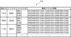
- the ticket has a data structure as shown in FIG.
- the wireless access information is a wireless identification ID and an authentication code. The authenticity of the ticket is verified to confirm that it has not been tampered with. Thereafter, the wireless connection can be correctly performed by specifying the connection destination device.
- the CPU 101 executes the karaoke service (S112) after establishing connection states with all the connection destination devices (S109 to S111) in the same manner as steps S12 to S12 (see FIG. 5) of the first embodiment.
- the CPU 101 determines whether a device addition instruction has been input (S113). When a device addition instruction is given (S113: YES), the CPU 101 accepts designation of an additional device (S114).
- the receiving method is the same as the method of the first embodiment.
- the CPU 101 transmits a device addition request to the device management server 210 (S115).
- the device addition request is information requesting to reissue a ticket added with an additional device as a connection destination device, and includes the terminal ID of the information terminal 100 and the wireless access information of the additional device.
- the ticket in which the information on the added device is added to the previously issued ticket information is reissued and transmitted to the information terminal 100.
- the CPU 101 receives the ticket reissued by the device management server 210 (S106: YES).
- the CPU 101 verifies the signature of the ticket and reads information (S108).
- Information of the additional device is added to the information of the connection destination device of the ticket.
- the CPU 101 determines that there is a connection destination device for which the connection state is not established (S109: NO), and generates a wireless session with the additional device based on the wireless access information of the additional device (S110). .
- the processing after returning to step S109 is as described above.
- the CPU 101 When a device addition instruction is not input during service execution (S113: NO), the CPU 101 performs processing (S116 to S117) until the connection is released, as in the first embodiment (S16, S19 in FIG. 5). Thereafter, the CPU 101 transmits the connection time together with the terminal ID to the device management server 210 (S118). The process shown in FIG.
- the process illustrated in FIG. 7 is started when the power of the device management server 210 is turned on.
- the CPU 211 of the device management server 210 determines whether a ticket request has been received from any of the information terminals 100 connected via the network 10 (S201).
- the CPU 211 extracts the location ID and the application ID included in the ticket request (S202).
- the place ID is the terminal location information of the information terminal (hereinafter referred to as the request terminal) 100 that is the transmission source of the ticket request
- the application ID is the application ID of the activation application corresponding to the service specified by the user at the request terminal 100. is there.
- the CPU 211 refers to the used device DB 216 (see FIG. 3) stored in the HDD 215 to determine a used device corresponding to the extracted application ID of the activated application (S203). Further, the CPU 211 refers to the installed device DB 217 (see FIG. 4) stored in the HDD 215 to identify the installed device installed at the location indicated by the extracted location ID (S204).
- the used device determination method and the installation device identification method in steps S203 to S204 are the same as steps S7 to S8 (see FIG. 5) of the first embodiment.
- the CPU 211 determines whether or not all the installed devices that match the used device are available based on the specified used device and the device ID of the installed device (S205).
- the determination method in step S205 is the same as that in step S9 (see FIG. 5) in the first embodiment.
- the CPU 211 transmits to the requesting terminal 100 a service unavailability notification including information indicating that the connection destination device could not be determined (S206). Then, the CPU 211 returns to the process of step S201.
- the CPU 211 determines that all the installed devices that match the used device are available (S205: YES). Then, the CPU 211 determines the installed device that matches the used device as the connection destination device (S207). Then, the CPU 211 issues a ticket (see FIG. 8) including wireless access information necessary for the requesting terminal 100 to establish a connection state with the connection destination device (S208). As described above, the ticket is signed with the secret key of the public key encryption algorithm. The CPU 211 adds the terminal ID of the requesting terminal 100 and information related to the issued ticket to the issued ticket list 218 (see FIG. 9) prepared in a predetermined storage area of the RAM 213. As shown in FIG.
- the terminal ID of the requesting terminal 100, the application ID of the activation application, the device ID of the connection destination device, and the wireless access information of the connection destination device correspond to each other.
- the CPU 211 transmits a ticket to the request terminal 100 (S209), and returns to the process of step S201.
- the CPU 211 determines whether or not the connection time has been received from any of the information terminals 100 connected via the network 10 (S210).
- the CPU 211 refers to the issued ticket list 218 (see FIG. 9) and the installed device DB 217 (see FIG. 4) in the RAM 103.
- the CPU 211 calculates a billing amount for the user of the information terminal 100 that is the transmission source of the connection time (S211).
- the billing amount calculation method is the same as that in step S20 in the first embodiment.
- the CPU 211 transmits the terminal ID of the information terminal 100 that has transmitted the calculated charging amount and connection time to a charging server (not shown) (S212). Further, the information related to the information terminal 100 that is the transmission source of the connection time is deleted from the issued ticket list 218, and the process returns to step S201.
- the CPU 211 determines whether a device addition request has been received from any of the information terminals 100 connected via the network 10 (S213).
- the CPU 211 reissues the ticket based on the issued ticket list 218 (see FIG. 9) in the RAM 103 and information included in the device addition request (S214). Specifically, the CPU 211 reads information on issued tickets specified by the terminal ID included in the device addition request from the issued ticket list 218. Further, the CPU 211 adds the wireless access information of the additional device included in the device addition request and reissues the ticket.
- the reissued ticket is also signed with the private key, just like a normal ticket.
- the CPU 211 transmits the reissued ticket to the information terminal 100 that is the transmission source of the device addition request (S215), and returns to the process of step S201.
- the CPU 211 determines whether an instruction to end the process has been input (S216). If an end instruction has not been input (S216: NO), the CPU 211 returns to the process of step S201. If an end instruction is input (S216: YES), the CPU 211 ends the process shown in FIG.
- the information terminal 100 acquires terminal position information by the information reading unit 108. Then, the information terminal 100 transmits a ticket request to the device management server 210.
- the ticket request includes terminal location information (location ID) and an application ID of an activation application that provides a service specified by the user of the information terminal 100.
- the device management server 210 refers to the used device DB 216 to determine a used device necessary for the activation application.
- the device management server 210 further refers to the installed device DB 217 to determine the installed device as the connection destination device. Send a ticket containing wireless access information.
- the wireless access information in this case is wireless access information necessary for establishing a wireless connection state with the connection destination device with respect to the information terminal 100.
- the information terminal 100 establishes a wireless connection state with the connection destination device based on the ticket information, and executes the service through a wireless session.
- the information terminal 100 is connected to an appropriate peripheral device installed at a place (position) where the information terminal 100 exists, according to the activation application.
- the connection state can be established dynamically.
- the information terminal 100 corresponds to the information terminal of the present invention
- the device management server 210 corresponds to the server of the present invention.
- the CPU 211 that acquires the location ID from the information terminal 100 in step S202 in FIG. 7 corresponds to the terminal information acquisition unit.
- the CPU 211 that performs the used device determination process in step S203 in FIG. 7 corresponds to a device determination unit.
- the HDD 215 storing the installation device DB 217 corresponds to the first storage unit.
- the CPU 211 that performs the connection destination device determination process in step S207 corresponds to a fourth connection destination determination unit.
- the CPU 211 that performs the process of transmitting the ticket to the information terminal 100 in step S209 corresponds to a connection destination notification unit.
- the third embodiment will be described with reference to FIGS. 10 and 11.
- the karaoke service execution process is shared between the server group 200 and the information terminal 100, but some of the shared contents are different. Therefore, in the following, details of the processing different from the second embodiment will be described while omitting the description of the same processing as in the second embodiment.
- steps in which the same processing as the processing of the second embodiment (see FIG. 6 and FIG. 7) is performed are assigned the same step number.
- the information terminal 100 determines the device used and the connection destination device.
- the used device DB 216 is downloaded to the information terminal 100 (S131).
- the method is the same as step S2 of the first embodiment (see FIG. 5). Similar to the second embodiment, the processes of steps S102 to S104 are performed. Subsequently, a use device corresponding to the activated application is determined (S132). The method for determining the device to be used is the same as step S7 (see FIG. 5) of the first embodiment.
- the ticket request is information for requesting information on an installed device in a place where the information terminal 100 exists.
- the ticket request includes the terminal ID of the information terminal 100 and the location ID that is terminal location information.
- the CPU 101 reads the ticket information (S135).
- the ticket includes the device ID of the installed device in the place where the information terminal 100 exists. Therefore, the CPU 101 has all the peripheral devices that match the device in use at the location where the information terminal 100 exists based on the device ID and the device ID of the device used that is determined in step S132 and stored in the RAM 103. It is determined whether or not (S136).
- the determination method here is the same as step S9 (see FIG. 5) of the first embodiment.
- the CPU 101 displays a message indicating that the service cannot be executed on the display unit 106 and notifies the user (S137). Then, the CPU 101 ends the process shown in FIG. If all the installed devices that match the used device are available (S136: YES), the CPU 101 determines the installed device that matches the used device as the connection destination device (S138). Subsequent connection state establishment processing and karaoke service execution processing (S109 to S112) are the same as in the second embodiment.
- the second embodiment if there is an instruction to add a device during service execution, processing for connecting to the additional device is performed (see steps S113 to S115 in FIG. 6), but this processing is performed as in the third embodiment. May be omitted.
- the connection time with the connection destination device is released (S117), and then the connection time is transmitted to the device management server 210 for calculating the billing amount. (See step S118 in FIG. 6). This process may be omitted as in the third embodiment. In this case, the billing amount may be calculated by another arbitrary method.
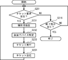
- the CPU 211 When a ticket request is received from any one of the information terminals 100 (S201: YES), the CPU 211 extracts a location ID included in the received ticket request (S231). Then, with reference to the installation device DB 217 (see FIG. 4) of the HDD 215, the installation device in the location indicated by the location ID, that is, the location where the information terminal 100 that is the transmission source of the ticket request exists is specified (S232). Then, the CPU 211 issues a ticket including information related to the installed device (S233).
- the ticket of the third embodiment includes, for example, a location ID, an application ID, the number of installed devices, a device ID of each installed device, and wireless access information.
- the device ID of each installed device is information necessary for the information terminal 100 to determine a connection destination device.
- the CPU 211 After transmitting the ticket (S234), the CPU 211 returns to the process of step S201, and when an end instruction is input (S216: YES), the process of FIG. 11 ends.
- device addition and charge amount calculation processing are omitted.
- the process shown in FIG. 11 does not include the processes of steps S210 to S215 of the second embodiment.
- the information terminal 100 acquires terminal position information by the information reading unit 108. Further, the used device corresponding to the activated application is determined with reference to the used device DB 216. Then, a ticket request including terminal location information (location ID) is transmitted to the device management server 210.
- the device management server 210 refers to the installed device DB 217 and identifies the installed device installed at the location indicated by the terminal position information. Then, a ticket including information regarding the specified installed device is transmitted to the information terminal 100.
- the information terminal 100 determines a connection destination device based on information on the device used and the installed device included in the received ticket. Then, a wireless connection state is established with the connection destination device, and the service is executed through a wireless session.
- the information terminal 100 is connected to an appropriate peripheral device installed in a place (position) where the information terminal 100 exists, according to the activation application.
- the connection state can be established dynamically.
- the information terminal 100 corresponds to the information terminal of the present invention.
- the CPU 101 that acquires the location ID read by the information reading unit 108 in step S103 in FIG. 10 corresponds to the position information acquisition unit.
- the CPU 101 that performs the used device determination process in step S132 corresponds to a device determination unit.
- the CPU 101 that transmits the ticket request by controlling the wireless communication unit 105 in step S133 corresponds to the first transmission unit.
- the CPU 101 that obtains the ticket in step S134 corresponds to the first receiving unit.
- the CPU 101 that performs connection destination device determination processing in step S138 corresponds to second connection destination determination means.
- the CPU 101 that controls the wireless communication unit 105 to generate a session corresponds to a connection establishment unit.
- FIGS. 12 and 13 a fourth embodiment will be described with reference to FIGS. 12 and 13.
- the processing related to the karaoke service execution is performed by the server group 200 and the information terminal 100. Only part of the content is different. Therefore, in the following, details of the processing different from the second embodiment will be described while omitting the description of the same processing as in the second embodiment.
- the same step number is assigned to the step in which the same process as the process of the second embodiment (see FIG. 6 and FIG. 7) is performed.
- the connection destination device is determined by the information terminal 100.
- the installation device DB 217 (see FIG. 4) is downloaded to the information terminal 100 (S151).
- the method is the same as step S3 (refer FIG. 5) of 1st embodiment. Similar to the second embodiment, the processes of steps S102 to S104 are performed. *
- the CPU 101 transmits a ticket request to the device management server 210 (S152).
- the ticket request according to the fourth embodiment is information for requesting information on a device used corresponding to the activation application.
- the ticket request includes the terminal ID of the information terminal 100 and the application ID of the activation application.
- the CPU 101 reads ticket information (S154).
- the ticket includes the device ID of the device used corresponding to the activation application. Therefore, the CPU 101 refers to the installed device DB 217 to determine whether or not all peripheral devices that match the device in use are available at the location where the information terminal 100 exists (S155).
- the determination method here is the same as step S9 (see FIG. 5) of the first embodiment.
- the CPU 101 displays a message indicating that the service cannot be executed on the display unit 106 and notifies the user (S156). Then, the CPU 101 ends the process shown in FIG. If all the installed devices that match the used device are available (S155: YES), the CPU 101 determines the installed device that matches the used device as the connection destination device (S157). Subsequent connection state establishment processing, karaoke service execution processing (S109 to S112), and processing end processing (S116 to S117) are the same as in the second embodiment.
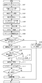
- the CPU 211 When the ticket request is received from any one of the information terminals 100 (S201: YES), the CPU 211 extracts the application ID of the activation application included in the received ticket request (S251). Then, the used device DB 216 (see FIG. 3) in the HDD 215 is referred to, and the used device used in the activation application indicated by the application ID is determined (S252). Then, the CPU 211 issues a ticket including information on the device used (S253). Although illustration is omitted, the ticket of the fourth embodiment includes, for example, an application ID and a device ID of the device used. After transmitting the ticket (S254), the CPU 211 returns to the process of step S201, and when an end instruction is input (S216: YES), the process of FIG. 13 ends.
- the information terminal 100 acquires terminal position information by the information reading unit 108. After downloading the installed device DB 217 and the startup application, a ticket request including the application ID of the startup application is transmitted to the device management server 210.
- the device management server 210 refers to the used device DB 216 and determines a used device corresponding to the activated application. Then, a ticket including information on the device in use is transmitted to the information terminal 100.
- the information terminal 100 determines a connection destination device based on the information on the used device included in the received ticket and the information on the downloaded installed device DB. Then, a wireless connection state is established with the connection destination device, and the service is executed through a wireless session.
- the information terminal 100 is connected to an appropriate peripheral device installed at a location (position) where the information terminal 100 exists, according to the activation application.
- the connection state can be established dynamically.
- the information terminal 100 corresponds to the information terminal of the present invention.
- the CPU 101 that acquires the location ID read by the information reading unit 108 in step S103 in FIG. 12 corresponds to a position information acquisition unit.
- the CPU 101 that transmits the ticket request by controlling the wireless communication unit 105 in step S153 corresponds to a second transmission unit.
- the CPU 101 that obtains the ticket in step S153 corresponds to the second receiving unit.
- the CPU 101 that performs the connection destination device determination process in step S157 corresponds to a third connection destination determination unit.
- the nonvolatile memory 104 that stores the installation device DB 217 corresponds to the first storage unit.
- the CPU 101 that controls the wireless communication unit 105 to generate a session corresponds to a connection establishment unit.
- the present invention is not limited to the above embodiment, and various modifications are possible.
- the processing of the information terminal 100 has been described by taking as an example the case where a karaoke service is used.
- the present invention is also applicable to other systems.
- the process described in the embodiment is a process in which the information terminal establishes a connection state with a microphone, an audio device, and a projector installed around the position when the startup application is an application that executes a presentation. Applicable.
- the server group 200 includes four servers 210 to 240.
- the server group 200 is regarded as one computer. Therefore, the processes performed in any of the servers 210 to 240 can be collectively regarded as a process in one server.
- the server group 200 may actually be configured as one server. Further, all the databases such as the used device DB 216 and the installed device DB 217 may be stored in a storage device of a server in the server group 200, and the CPU of the server may perform all the processes.
- the example in which the same peripheral device is installed in the room 30 illustrated in FIG. 1 has been described. Different types of peripheral devices may be installed for each room 30.
- an IC tag 80 storing a place ID may be installed in a karaoke facility.
- the location ID is read from the IC tag 80 by the information reading unit 108 (non-contact IC reader).
- any other method may be adopted. For example, a method of reading bar code or two-dimensional code information or visible light communication may be used.
- a process of automatically acquiring GPS information latitude, longitude, altitude
- the installation device DB 217 (see FIG. 4) stores specific ranges of latitude, longitude, and altitude in association with the location ID. Then, the information terminal 100 or the device management server 210 may specify the installed device based on the location ID corresponding to the range to which the latitude, longitude, and altitude of the information terminal 100 belong.
- the basic application, the used device DB 216, and the installed device DB 217 are not necessarily downloaded at this timing.
- the basic application, the used device DB 216, and the installed device DB 217 may be downloaded in advance.
- the downloaded data may be stored in the nonvolatile memory 104.
- the process shown in FIG. 5 and the like may be started when the basic application stored in the nonvolatile memory 104 is activated.
- the used device DB 216 When the used device is determined, the used device DB 216 is not necessarily used.
- the used device DB 216 stores a plurality of karaoke service applications and their used devices in association with each other.
- the minimum peripheral devices for example, the audio equipment 71, the microphone 72, and the display 73
- the database does not necessarily need to be stored in the built-in nonvolatile memory 104. For example, processing may be performed using what is stored in an external memory such as a memory card.
- At least one of the device addition processing and the processing related to the calculation of the charge amount may be omitted.
- at least one of a device addition process and a process related to calculation of a charge amount may be added as in the first and second embodiments. Further, the charge amount may be calculated based only on the attribute of the connection destination device regardless of the connection time.
- Information terminal 101
- CPU 104
- Non-volatile memory 105
- Wireless communication unit 108
- Information reading unit 200
- Server group 210
- Device management server 211
- CPU 215 HDD 216
Landscapes
- Engineering & Computer Science (AREA)
- Physics & Mathematics (AREA)
- Acoustics & Sound (AREA)
- Multimedia (AREA)
- General Engineering & Computer Science (AREA)
- Computer Networks & Wireless Communication (AREA)
- Reverberation, Karaoke And Other Acoustics (AREA)
- Telephone Function (AREA)
- Telephonic Communication Services (AREA)
- Mobile Radio Communication Systems (AREA)
Abstract
L'invention concerne : un terminal d'informations pouvant établir une connexion dynamique avec un dispositif périphérique adapté en fonction de l'application à utiliser ; un serveur pouvant communiquer avec ledit terminal d'informations ; un procédé de commande de connexion ; et un programme de commande de connexion. Ledit terminal d'informations capture, à partir d'une étiquette à IC placée sur un équipement de karaoké, un ID d'emplacement qui indique la position de ladite étiquette à IC (S5). Une application de lancement correspondant à un service de karaoké à utiliser est téléchargée sur ledit terminal d'informations et commence à fonctionner (S6). Grâce à la consultation d'une base de données de dispositifs utilisés, il est déterminé qu'un dispositif utilisé est un dispositif périphérique utilisé par ladite application de lancement (S7). Grâce à la consultation d'une base de données de dispositifs installés, il est déterminé que les dispositifs périphériques qui sont compatibles avec les dispositifs utilisés et qui sont installés à l'emplacement indiqué par l'ID d'emplacement sont des dispositifs destinations de connexion (S11). Le terminal d'informations commande une partie de communication sans fil, génère une session sans fil avec lesdits dispositifs destinations de connexion et établit une connexion (S13).
Applications Claiming Priority (2)
| Application Number | Priority Date | Filing Date | Title |
|---|---|---|---|
| JP2011-043076 | 2011-02-28 | ||
| JP2011043076A JP5472159B2 (ja) | 2011-02-28 | 2011-02-28 | 情報端末、サーバ、接続先決定方法およびプログラム |
Publications (1)
| Publication Number | Publication Date |
|---|---|
| WO2012117799A1 true WO2012117799A1 (fr) | 2012-09-07 |
Family
ID=46757739
Family Applications (1)
| Application Number | Title | Priority Date | Filing Date |
|---|---|---|---|
| PCT/JP2012/052352 Ceased WO2012117799A1 (fr) | 2011-02-28 | 2012-02-02 | Terminal d'informations, serveur, et procédé et programme de détermination de destinations de connexion |
Country Status (2)
| Country | Link |
|---|---|
| JP (1) | JP5472159B2 (fr) |
| WO (1) | WO2012117799A1 (fr) |
Families Citing this family (8)
| Publication number | Priority date | Publication date | Assignee | Title |
|---|---|---|---|---|
| JP6299121B2 (ja) * | 2013-09-05 | 2018-03-28 | ヤマハ株式会社 | 音波形データ処理装置 |
| JP6451337B2 (ja) * | 2015-01-20 | 2019-01-16 | 株式会社リコー | 情報処理システム及び通信方法 |
| US9690525B2 (en) | 2015-05-06 | 2017-06-27 | Citrix Systems, Inc. | Availability of devices based on location |
| JP6645249B2 (ja) * | 2016-02-22 | 2020-02-14 | 株式会社リコー | 機器制御システム、機器制御方法 |
| JP6809151B2 (ja) * | 2016-10-24 | 2021-01-06 | ヤマハ株式会社 | 端末装置およびプログラム |
| JP6630809B2 (ja) * | 2018-12-03 | 2020-01-15 | Kddi株式会社 | データ管理装置、データ管理方法及びデータ通信システム |
| JP6943926B2 (ja) * | 2019-07-30 | 2021-10-06 | 株式会社第一興商 | カラオケシステム及びカラオケ装置 |
| JP7485570B2 (ja) * | 2020-08-25 | 2024-05-16 | 株式会社第一興商 | コンテンツ出力装置 |
Citations (3)
| Publication number | Priority date | Publication date | Assignee | Title |
|---|---|---|---|---|
| JP2005071293A (ja) * | 2003-08-28 | 2005-03-17 | Yasuki Ogura | 作業環境提供システム |
| JP2006259839A (ja) * | 2005-03-15 | 2006-09-28 | Fujitsu Ltd | 統合機能制御プログラム、統合機能制御装置、統合機能制御方法 |
| JP2006525597A (ja) * | 2003-03-07 | 2006-11-09 | オープンピーク インコーポレイテッド | 制御された居住環境または非居住環境を管理するための方法、システム、およびコンピュータープログラム |
Family Cites Families (2)
| Publication number | Priority date | Publication date | Assignee | Title |
|---|---|---|---|---|
| JP2003177980A (ja) * | 2001-12-12 | 2003-06-27 | Sony Corp | 情報提供システム、情報提供装置および方法、情報処理装置および方法、記録媒体、並びにプログラム |
| JP2009187103A (ja) * | 2008-02-04 | 2009-08-20 | Sharp Corp | 移動通信端末、印刷システム |
-
2011
- 2011-02-28 JP JP2011043076A patent/JP5472159B2/ja not_active Expired - Fee Related
-
2012
- 2012-02-02 WO PCT/JP2012/052352 patent/WO2012117799A1/fr not_active Ceased
Patent Citations (3)
| Publication number | Priority date | Publication date | Assignee | Title |
|---|---|---|---|---|
| JP2006525597A (ja) * | 2003-03-07 | 2006-11-09 | オープンピーク インコーポレイテッド | 制御された居住環境または非居住環境を管理するための方法、システム、およびコンピュータープログラム |
| JP2005071293A (ja) * | 2003-08-28 | 2005-03-17 | Yasuki Ogura | 作業環境提供システム |
| JP2006259839A (ja) * | 2005-03-15 | 2006-09-28 | Fujitsu Ltd | 統合機能制御プログラム、統合機能制御装置、統合機能制御方法 |
Also Published As
| Publication number | Publication date |
|---|---|
| JP2012182590A (ja) | 2012-09-20 |
| JP5472159B2 (ja) | 2014-04-16 |
Similar Documents
| Publication | Publication Date | Title |
|---|---|---|
| JP5472159B2 (ja) | 情報端末、サーバ、接続先決定方法およびプログラム | |
| US10560801B2 (en) | Beacon applications for content discovery and interaction | |
| US9400877B2 (en) | Server device and service provision method | |
| CN104769564B (zh) | 通信终端、通信方法以及通信系统 | |
| CN111159474B (zh) | 基于区块链的多线取证方法、装置、设备及存储介质 | |
| WO2003100682A1 (fr) | Systeme de traitement d'informations | |
| CN111241115B (zh) | 数据同步方法、装置、设备及存储介质 | |
| CN111045568B (zh) | 基于区块链的虚拟物品处理方法、装置、设备及存储介质 | |
| KR20050118101A (ko) | 정보 처리 시스템, 정보 처리 장치 및 방법, 그리고프로그램 | |
| CN110597924A (zh) | 基于区块链的用户标识处理方法、装置、设备及存储介质 | |
| JP5230263B2 (ja) | 複数のカラオケ演奏端末間におけるログイン利用者コピーシステム | |
| WO2013001573A1 (fr) | Système de gestion de compte, et procédé et programme de commande de système de gestion de compte | |
| JP6960362B2 (ja) | 認証システム及び認証方法 | |
| JP5694898B2 (ja) | パーソナル携帯端末を用いたカラオケ選曲システム | |
| JP5694899B2 (ja) | パーソナル携帯端末を用いたカラオケ選曲システム | |
| JP2003178022A (ja) | 識別情報発行装置及び方法、識別情報発行プログラムを記憶した記憶媒体、識別情報発行プログラム、情報処理装置及び方法、情報処理プログラムを記憶した記憶媒体、情報処理プログラム、情報処理システム | |
| EP3716592B1 (fr) | Procédé de fourniture de contenu et dispositif électronique prenant en charge celui-ci | |
| JP5975800B2 (ja) | パーソナル携帯端末を用いたカラオケ選曲システム | |
| CN110532324A (zh) | 基于区块链的公告信息展示方法、装置、设备及存储介质 | |
| JP6220420B2 (ja) | サウンドを利用したソーシャルネットワークサービス提供装置、その方法、及びプログラム | |
| TW201251421A (en) | Karaoke music selection system using personal portable terminal | |
| CN110597840A (zh) | 基于区块链的伴侣关系建立方法、装置、设备及存储介质 | |
| US20240427820A1 (en) | Automated Remote Music Identification and Publishing System and Method | |
| WO2024263865A1 (fr) | Système et procédé d'identification et de publication automatisées de musique à distance | |
| JP2004151362A (ja) | 情報処理装置及びネットワークシステム |
Legal Events
| Date | Code | Title | Description |
|---|---|---|---|
| 121 | Ep: the epo has been informed by wipo that ep was designated in this application |
Ref document number: 12752544 Country of ref document: EP Kind code of ref document: A1 |
|
| NENP | Non-entry into the national phase |
Ref country code: DE |
|
| 122 | Ep: pct application non-entry in european phase |
Ref document number: 12752544 Country of ref document: EP Kind code of ref document: A1 |