WO2012118027A1 - ハイブリッド式建設機械 - Google Patents
ハイブリッド式建設機械 Download PDFInfo
- Publication number
- WO2012118027A1 WO2012118027A1 PCT/JP2012/054814 JP2012054814W WO2012118027A1 WO 2012118027 A1 WO2012118027 A1 WO 2012118027A1 JP 2012054814 W JP2012054814 W JP 2012054814W WO 2012118027 A1 WO2012118027 A1 WO 2012118027A1
- Authority
- WO
- WIPO (PCT)
- Prior art keywords
- electric motor
- storage device
- power storage
- turning
- hydraulic
- Prior art date
- Legal status (The legal status is an assumption and is not a legal conclusion. Google has not performed a legal analysis and makes no representation as to the accuracy of the status listed.)
- Ceased
Links
Images


Classifications
-
- E—FIXED CONSTRUCTIONS
- E02—HYDRAULIC ENGINEERING; FOUNDATIONS; SOIL SHIFTING
- E02F—DREDGING; SOIL-SHIFTING
- E02F9/00—Component parts of dredgers or soil-shifting machines, not restricted to one of the kinds covered by groups E02F3/00 - E02F7/00
- E02F9/20—Drives; Control devices
-
- E—FIXED CONSTRUCTIONS
- E02—HYDRAULIC ENGINEERING; FOUNDATIONS; SOIL SHIFTING
- E02F—DREDGING; SOIL-SHIFTING
- E02F9/00—Component parts of dredgers or soil-shifting machines, not restricted to one of the kinds covered by groups E02F3/00 - E02F7/00
- E02F9/20—Drives; Control devices
- E02F9/2025—Particular purposes of control systems not otherwise provided for
-
- E—FIXED CONSTRUCTIONS
- E02—HYDRAULIC ENGINEERING; FOUNDATIONS; SOIL SHIFTING
- E02F—DREDGING; SOIL-SHIFTING
- E02F9/00—Component parts of dredgers or soil-shifting machines, not restricted to one of the kinds covered by groups E02F3/00 - E02F7/00
- E02F9/08—Superstructures; Supports for superstructures
- E02F9/10—Supports for movable superstructures mounted on travelling or walking gears or on other superstructures
- E02F9/12—Slewing or traversing gears
- E02F9/121—Turntables, i.e. structure rotatable about 360°
- E02F9/128—Braking systems
-
- E—FIXED CONSTRUCTIONS
- E02—HYDRAULIC ENGINEERING; FOUNDATIONS; SOIL SHIFTING
- E02F—DREDGING; SOIL-SHIFTING
- E02F9/00—Component parts of dredgers or soil-shifting machines, not restricted to one of the kinds covered by groups E02F3/00 - E02F7/00
- E02F9/20—Drives; Control devices
- E02F9/2058—Electric or electro-mechanical or mechanical control devices of vehicle sub-units
- E02F9/2091—Control of energy storage means for electrical energy, e.g. battery or capacitors
-
- E—FIXED CONSTRUCTIONS
- E02—HYDRAULIC ENGINEERING; FOUNDATIONS; SOIL SHIFTING
- E02F—DREDGING; SOIL-SHIFTING
- E02F9/00—Component parts of dredgers or soil-shifting machines, not restricted to one of the kinds covered by groups E02F3/00 - E02F7/00
- E02F9/20—Drives; Control devices
- E02F9/2058—Electric or electro-mechanical or mechanical control devices of vehicle sub-units
- E02F9/2095—Control of electric, electro-mechanical or mechanical equipment not otherwise provided for, e.g. ventilators, electro-driven fans
-
- E—FIXED CONSTRUCTIONS
- E02—HYDRAULIC ENGINEERING; FOUNDATIONS; SOIL SHIFTING
- E02F—DREDGING; SOIL-SHIFTING
- E02F9/00—Component parts of dredgers or soil-shifting machines, not restricted to one of the kinds covered by groups E02F3/00 - E02F7/00
- E02F9/20—Drives; Control devices
- E02F9/22—Hydraulic or pneumatic drives
- E02F9/2217—Hydraulic or pneumatic drives with energy recovery arrangements, e.g. using accumulators, flywheels
-
- H—ELECTRICITY
- H02—GENERATION; CONVERSION OR DISTRIBUTION OF ELECTRIC POWER
- H02P—CONTROL OR REGULATION OF ELECTRIC MOTORS, ELECTRIC GENERATORS OR DYNAMO-ELECTRIC CONVERTERS; CONTROLLING TRANSFORMERS, REACTORS OR CHOKE COILS
- H02P27/00—Arrangements or methods for the control of AC motors characterised by the kind of supply voltage
- H02P27/04—Arrangements or methods for the control of AC motors characterised by the kind of supply voltage using variable-frequency supply voltage, e.g. inverter or converter supply voltage
- H02P27/06—Arrangements or methods for the control of AC motors characterised by the kind of supply voltage using variable-frequency supply voltage, e.g. inverter or converter supply voltage using DC to AC converters or inverters
-
- H—ELECTRICITY
- H02—GENERATION; CONVERSION OR DISTRIBUTION OF ELECTRIC POWER
- H02P—CONTROL OR REGULATION OF ELECTRIC MOTORS, ELECTRIC GENERATORS OR DYNAMO-ELECTRIC CONVERTERS; CONTROLLING TRANSFORMERS, REACTORS OR CHOKE COILS
- H02P29/00—Arrangements for regulating or controlling electric motors, appropriate for both AC and DC motors
- H02P29/02—Providing protection against overload without automatic interruption of supply
- H02P29/024—Detecting a fault condition, e.g. short circuit, locked rotor, open circuit or loss of load
- H02P29/0241—Detecting a fault condition, e.g. short circuit, locked rotor, open circuit or loss of load the fault being an overvoltage
-
- H—ELECTRICITY
- H02—GENERATION; CONVERSION OR DISTRIBUTION OF ELECTRIC POWER
- H02P—CONTROL OR REGULATION OF ELECTRIC MOTORS, ELECTRIC GENERATORS OR DYNAMO-ELECTRIC CONVERTERS; CONTROLLING TRANSFORMERS, REACTORS OR CHOKE COILS
- H02P29/00—Arrangements for regulating or controlling electric motors, appropriate for both AC and DC motors
- H02P29/02—Providing protection against overload without automatic interruption of supply
- H02P29/024—Detecting a fault condition, e.g. short circuit, locked rotor, open circuit or loss of load
- H02P29/026—Detecting a fault condition, e.g. short circuit, locked rotor, open circuit or loss of load the fault being a power fluctuation
Definitions
- the present invention relates to a hybrid construction machine having a revolving structure such as a hydraulic excavator, and more particularly to a hybrid construction machine having a revolving structure including an electric motor for driving the revolving structure and a power storage device.
- construction machines having a swinging body such as a hydraulic excavator are mainly used to drive a hydraulic pump with an engine, rotate a hydraulic motor with hydraulic pressure discharged from the hydraulic pump, and drive a swinging body that is an inertial body.
- both electric motors and hydraulic motors driven by the supply of electrical energy from the power storage device have been used to improve engine fuel efficiency, reduce noise levels, and reduce exhaust gas volume.
- a hybrid system that drives a revolving structure has been proposed (see, for example, Patent Document 1).
- the construction machine described in Patent Document 1 includes another electric motor for power generation that supplies electric energy to the power storage device when the power storage level of the power storage device decreases. ing.
- Patent Document 1 discloses a torque commanding a driving torque of an electric motor as a control means of a hybrid construction machine in relation to a differential pressure between an in-side and an out-side of a swing driving hydraulic motor.
- a technique including command means is disclosed.
- Patent Document 1 discloses the ratio of the torque of the hydraulic motor to the torque of the electric motor during acceleration driving, and the ratio of the torque of the hydraulic motor to the torque of the electric motor during deceleration driving.
- a technique for defining the differential pressure as a parameter is also disclosed (for example, paragraph 0060). According to Patent Document 1, according to these techniques, it is possible to continuously and smoothly control the rotating body, which is an inertial body, and to effectively incorporate the energy at the time of braking as electric energy into the power storage device. (Eg, paragraphs 0033, 0034).
- Patent Document 1 uses the differential pressure between the in-side and out-side of the hydraulic motor as a parameter, and each of the torque shared by the hydraulic motor during acceleration driving and deceleration driving and the torque shared by the electric motor.
- the ratio is obtained to obtain the torque necessary for driving the swivel body, but it is actually very difficult to freely change the output of the hydraulic motor during the operation of the machine .
- the amount of power stored in the power storage device increases or decreases.
- Patent Document 1 regarding charge / discharge management of a power storage device, when the amount of power stored in the power storage device is lower than a predetermined value, the power generation motor is driven and the generated power is supplied to the power storage device. (Paragraphs 0053 and 0055) is merely described, and there is no description of energy management in consideration of the adverse effect on the life due to overcharging of the power storage device.
- the driving torque shared by the hydraulic motor and the electric motor is such that an operator accustomed to the operation of the conventional construction machine that drives the revolving body using only the hydraulic motor can be operated without a sense of incongruity. Need to be controlled appropriately.
- the electric motor consumes at the time of driving (powering) and the power storage device connected to the electric motor charges and discharges the energy generated at the time of braking (regeneration). Since the capacity of the power storage device is limited, it is particularly important to properly manage the amount of power stored in the power storage device, that is, energy management.
- the amount of electricity stored in the power storage device may exceed the appropriate range.
- the present invention has been made in order to solve the problems of the prior art, and the purpose thereof is to provide a operability of a turning operation that does not give a sense of incongruity with a conventional construction machine, and a power storage device having a large capacity.
- An object of the present invention is to provide a hybrid construction machine in which the amount of power stored in a power storage device is controlled within an appropriate range in consideration of life.
- the first invention is an engine, a hydraulic pump driven by the engine, a turning body, an electric motor and a hydraulic motor for driving the turning body, and driving the turning body.
- a turning operation lever operated by an operator a power storage device for storing electric energy to be supplied to the electric motor, and a signal corresponding to an operation amount and an operation direction of the turning operation lever,
- a controller for controlling charging / discharging of the power storage device wherein the controller stores a discharge command area set in accordance with a turning speed of the revolving body with respect to a power storage amount of the power storage device, and the power storage device
- the power running amount of the electric motor is increased according to the amount of power stored in the power storage device.
- Calculates a plus driving torque command value of the electric motor it is assumed that the plus driving torque command value for driving the swing body and a computing section for output to the electric motor side.
- the second invention is an engine, a hydraulic pump driven by the engine, a revolving body, an electric motor and a hydraulic motor that drive the revolving body, and an operator that operates to drive the revolving body.
- Controls charging / discharging of the power storage device by inputting a signal corresponding to an operation amount and an operation direction of the turning operation lever, a power storage device that stores electric energy to be supplied to the electric motor, and an operation amount of the turning operation lever
- a controller that stores a charge command area that is set according to a turning speed of the swivel body with respect to a storage amount of the power storage device; and a storage unit that stores the storage amount of the power storage device.
- the electric motor When the charging command area stored in is reached, the electric motor is driven to increase the regeneration amount of the electric motor in accordance with the storage amount of the power storage device. Calculates a torque command value, it is assumed that the plus driving torque command value to brake the swing structure and a computing section for output to the electric motor side.
- the controller further stores a normal use area that is an optimum use range of the power storage device with respect to a power storage amount of the power storage device; Torque for driving and braking the swivel body according to the operation amount and operation direction of the turning operation lever when the amount of electricity stored in the power storage device is within the normal use range stored in the storage unit And a calculation unit that calculates a command value and outputs the torque command value to the electric motor side.
- the controller drives the revolving structure according to the additional drive torque command value, the operation amount and the operation direction of the turning operation lever.
- a hydraulic command combined control means for calculating an electric motor torque command from the torque command value for performing braking and outputting the electric motor torque command to the electric motor side.
- the additional drive torque command value calculated according to the amount of power stored in the power storage device is the driving or braking of the revolving structure.
- the amount of fluctuation varies depending on the amount of electricity stored under the same conditions, but the fluctuation torque range is the total torque obtained by adding the torque of the electric motor and the torque of the hydraulic motor under the same conditions as the driving or braking of the revolving structure. It is characterized by being 20% or less with respect to the standard value.
- the swing electric motor can be driven and controlled by the torque command signal obtained by adding the torque of the swing electric motor to the reference value, the power storage amount of the power storage device is within an appropriate range considering the life. Can manage. As a result, it is not necessary to increase the capacity of the power storage device and to secure the installation space thereof, and it is possible to ensure the operability of the turning operation comparable to that of the conventional construction machine.
- FIG. 1 is a side view of a hydraulic excavator to which an embodiment of a hybrid construction machine of the present invention is applied.
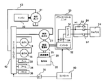
- 1 is a system configuration diagram of an electric / hydraulic device that constitutes an embodiment of a hybrid construction machine of the present invention.
- FIG. 1 is a system configuration and control block diagram of an embodiment of a hybrid construction machine of the present invention. It is a characteristic view which shows the relationship between the lever operation amount in one embodiment of the hybrid type construction machine of this invention, and the drive torque of a hydraulic motor and an electric motor.
- It is a block diagram of the energy management control means which comprises one Embodiment of the hybrid type construction machine of this invention.
- FIG. 1 is a side view of a hydraulic excavator to which an embodiment of a hybrid construction machine of the present invention is applied
- FIG. 2 is a system configuration diagram of electric / hydraulic equipment constituting an embodiment of the hybrid construction machine of the present invention.
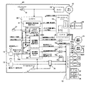
- FIG. 3 is a system configuration and control block diagram of an embodiment of the hybrid construction machine of the present invention
- FIG. 4 is a lever operation amount, hydraulic motor and electric motor of the hybrid construction machine of the embodiment of the present invention. It is a characteristic view which shows the relationship with a drive torque.
- the hydraulic excavator includes a traveling body 10, and a revolving body 20 and a shovel mechanism 30 provided on the traveling body 10 so as to be able to swivel.
- the traveling body 10 includes a pair of left and right crawlers 11 and a crawler frame 12 (only one side is shown in FIG. 1), a pair of traveling hydraulic motors 13 and 14 that independently drive and control each crawler 11 and a speed reduction mechanism thereof. Has been.
- the swing body 20 includes a swing frame 21, an engine 22 as a prime mover provided on the swing frame 21, a swing electric motor 25 and a swing hydraulic motor 27, and a capacitor that is a power storage device connected to the swing electric motor 25. 24, a speed reduction mechanism 26 that decelerates the rotation of the swing electric motor 25 and the swing hydraulic motor 27, and the like.
- the driving forces of the swing electric motor 25 and the swing hydraulic motor 27 are transmitted via the speed reduction mechanism 26, and the driving force thereof.
- the revolving unit 20 (the revolving frame 21) is driven to turn with respect to the traveling unit 10.
- an excavator mechanism (front device) 30 is mounted on the revolving unit 20.
- the shovel mechanism 30 includes a boom 31, a boom cylinder 32 for driving the boom 31, an arm 33 rotatably supported near the tip of the boom 31, and an arm cylinder 34 for driving the arm 33.
- the bucket 35 includes a bucket 35 rotatably supported at the tip of the arm 33, a bucket cylinder 36 for driving the bucket 35, and the like.
- a hydraulic system for driving hydraulic actuators such as the traveling hydraulic motors 13 and 14, the swing hydraulic motor 27, the boom cylinder 32, the arc cylinder 34, and the bucket cylinder 36 described above is provided on the swing frame 21 of the swing body 20.
- the hydraulic system 40 includes a hydraulic pump 41 (FIG. 2) serving as a hydraulic source for generating hydraulic pressure and a control valve 42 (FIG. 2) for driving and controlling each actuator.
- the hydraulic pump 41 is driven by the engine 22.
- the system configuration of the electric / hydraulic equipment of the hydraulic excavator will be outlined.
- the driving force of the engine 22 is transmitted to the hydraulic pump 41.
- the control valve 42 controls the flow rate and direction of the pressure oil supplied to the turning hydraulic motor 27 in accordance with a turning operation command (hydraulic pilot signal) from the turning operation lever device 72 (see FIG. 3). Further, the control valve 42 responds to an operation command (hydraulic pilot signal) from an operation lever device 73 (see FIG. 3) other than turning, and the boom cylinder 32, the arm cylinder 34, the bucket cylinder 36, and the traveling hydraulic motors 13 and 14 are operated. To control the flow rate and direction of pressure oil supplied to.
- the control valve 42 has a bleed-off opening area larger than that of a normal machine when the operation amount of the turning operation lever is in the intermediate range (between neutral and maximum), and the operation amount is in the intermediate range.
- the driving torque of the swing hydraulic motor 27 (torque in the direction in which the swing body 20 is driven) is made smaller than that of the normal machine.
- the control valve 42 has a meter-out opening area larger than that of the normal machine when the operation amount of the turning operation lever device 72 is in the intermediate range, and the braking torque of the turning hydraulic motor 27 when the operation amount is in the intermediate range. (Torque in the direction of braking the upper swing body 20) is made smaller than that of the normal machine.
- the turning control system sends a control signal in response to a command from the operation lever device 72 (see FIG. 3) to the control valve 42 and the power control unit 55 that controls charging / discharging of the capacitor 24.
- An output controller 80 is provided.
- the power control unit 55 includes a chopper 51, an inverter 52, a smoothing capacitor 54, and the like, and the main contactor 56 includes a main relay 57, an inrush current prevention circuit 58, and the like.
- the DC power from the capacitor 24 is boosted to a predetermined bus voltage by the chopper 51 and input to the inverter 52 for driving the swing electric motor 25.
- the smoothing capacitor 54 is provided to stabilize the bus voltage.
- the rotation shafts of the swing electric motor 25 and the swing hydraulic motor 27 are coupled to drive the swing body 20 via the speed reduction mechanism 26.
- the capacitor 24 is charged and discharged depending on the driving state (whether it is powering or regenerating) of the swing electric motor 25.
- the hydraulic excavator includes an ignition key 70 for starting the engine 22, and a gate lock lever device 71 that disables the operation of the hydraulic system by turning on the pilot pressure cutoff valve 76 when the operation is stopped.
- the hydraulic excavator includes the above-described controller 80, hydraulic / electrical converters 74a, 74bL, 74bR related to input / output of the controller 80, electric / hydraulic converters 75a, 75b, 75c, 75d, and a hydraulic single swing mode fixing switch 77. These constitute a turning control system.
- the hydraulic / electrical converters 74a, 74bL, 74bR are, for example, pressure sensors, and the electric / hydraulic converters 75a, 75b, 75c, 75d are, for example, electromagnetic proportional pressure reducing valves.
- the controller 80 includes an abnormality monitoring / abnormality processing control block (means) 81, an energy management control block (means) 82, a hydraulic / electric combined turning control block (means) 83, and a hydraulic single turning control block (means). ) 84, and a hydraulic / electric combined swing control block (means) 83 and a switching means 85 of the hydraulic single swing control block (means) 84.
- the error monitoring / abnormality processing control block 81 receives an error / failure / warning signal output from the power control unit 55.
- the energy management control block 82 outputs a remaining capacitor signal, a chopper current signal, a swing motor speed output from the power control unit 55, a rotation motor speed, and a pressure ⁇ electrical signal conversion device (for example, a pressure sensor) 74bL,
- the turning operation pressure converted into an electric signal by 74bR is input, and a request for adding torque to the hydraulic / electric combined turning control block 83 and a request for switching to the hydraulic single turning mode to the switching means 85 are output.
- the hydraulic / electric combined swing control block 83 is output from the swing operation lever 72 and is output from the power control unit 55 and a swing pilot pressure signal converted into an electrical signal by a hydraulic pressure ⁇ electric signal conversion device (for example, a pressure sensor) 74a.
- the turning motor speed and the turning operation pressure output from the control valve 42 and converted into electric signals by pressure ⁇ electrical signal conversion devices (for example, pressure sensors) 74bL and 74bR are inputted to the power control unit 55.
- An electric motor torque command, a pump absorption torque correction command to the hydraulic pump 41, and a swing hydraulic motor output torque decrease command to the control valve 42 are output.
- the pump absorption torque correction command and the swing hydraulic motor output torque decrease command are signals obtained by converting the signals converted into hydraulic pilot signals by the electrical ⁇ pressure signal conversion devices (for example, electromagnetic proportional valves) 75a and 75b into the hydraulic pump 41 and the control. Input to the valve 42.
- the electrical ⁇ pressure signal conversion devices for example, electromagnetic proportional valves
- the hydraulic single turning control block 84 inputs the turning pilot pressure signal output from the turning operation lever 72 and converted into an electric signal by the hydraulic pressure ⁇ electrical signal conversion device 74a, and supplies the hydraulic turning characteristic correction command to the control valve 42.
- the turning pilot pressure correction signal is output via the electrical ⁇ pressure signal conversion devices 75c and 75d.
- the switching means 85 is automatically switched by the controller 80 in accordance with the driving state of the swing body 20 and the amount of electricity stored in the capacitor 24, and is manually operated by a hydraulic single swing mode fixing switch 77 attached to the controller 80. You can also switch with.
- the swing control of the swing body 20 is performed by the hydraulic / electric combined swing control block 83. That is, when the operator operates the turning operation lever 72, a hydraulic pilot signal corresponding to the operation direction and operation amount is generated and input to the control valve 42, and to the controller 80 via the hydraulic pressure ⁇ electrical signal conversion device 74a. Also, a turning pilot pressure signal converted into an electric signal is input. As a result, the control valve for the swing hydraulic motor 27 is opened, the swing hydraulic motor 27 is driven, and the swing electric motor 25 is driven by receiving power supply from the capacitor 24.
- the controller 80 calculates a swing electric motor torque command sufficient to drive the swing electric motor 25 with a drive torque that compensates for the decrease in the drive torque of the swing hydraulic motor 27.
- FIG. 4 schematically shows the drive torque Tms1 of the swing electric motor 25 and the drive torque Tmo of the swing hydraulic motor 27 in accordance with the operation amount of the swing operation lever 72.
- the hydraulic / electric combined swing control block 83 adds the additional torque required from the energy management control block 82 to the drive torque Tms1 of the swing electric motor 25 and the drive torque Tmo of the swing hydraulic motor 27 according to the operation amount of the swing operation lever 72.
- the turning electric motor torque command is output to the power control unit 55.
- the additional torque is added to the drive torque Tms1 of the turning electric motor 25. A method of calculating the swing electric motor torque command in consideration of the additional torque will be described later.
- the amount of electricity stored in the capacitor 24 increases or decreases due to the difference between the electric energy consumed by the swing electric motor 25 during acceleration and the electric energy regenerated during deceleration.
- the energy management control block 82 controls the amount of electricity stored in the capacitor 24 within an appropriate range, and controls the amount of electricity stored in the capacitor 24 within an appropriate range by adjusting the torque added to the swing electric motor 25. Do.
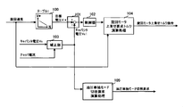
- FIG. 5 is a block diagram of the energy management control means constituting one embodiment of the hybrid construction machine of the present invention
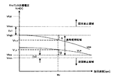
- FIG. 6 is a normal one stored in the controller constituting one embodiment of the hybrid construction machine of the present invention. It is a characteristic view explaining a use area
- 5 and 6 the same reference numerals as those shown in FIG. 1 to FIG. 4 are the same parts, and detailed description thereof is omitted.
- the torque in a range that does not give the operator a feeling of strangeness in the turning feeling is added to the driving torque or braking torque of the turning electric motor 25 to adjust the charged amount of the capacitor 24.
- the addition torque of the swing electric motor 25 is calculated with respect to the capacitor target voltage Vc *, and the capacitor voltage Vc is controlled by causing the swing electric motor 25 to perform a power running operation or a regenerative operation.
- the capacitor target voltage Vc * is set so as to depend on the kinetic energy of the upper swing body 20.
- the target voltage Vc * of the capacitor 24 is preset as a charge command VL * and a discharge command VH *, and is held in the storage unit as a table corresponding to the turning speed. For example, during turning power running operation, when the kinetic energy is larger than when the kinetic energy is small, that is, when the turning speed is high, the regenerative energy obtained during the regenerative operation is large.
- the capacitor target voltage Vc * is set low so as to lower the state. Similarly, during the regenerative operation, when the kinetic energy is small, that is, as the turning speed decreases, the capacitor target voltage Vc * is set high so that the charged state of the capacitor is kept high in preparation for the next powering operation. ing.
- FIG. 6 shows the contents of the table 1 defined by the function generator of the block 100 shown in FIG. 5, where Vmax is a capacitor voltage that defines the regeneration prohibited area, and Vhigh is a capacitor that defines the maximum voltage in the normal use area. Voltage, Vlow indicates a capacitor voltage that defines the minimum voltage in the normal use region, and Vmin indicates a capacitor voltage that defines the rotation prohibited region.
- the calculation unit in the energy management control block 82 allows the turning speed to be Wx in FIG. 6 and when the capacitor voltage Vc is higher than (Vh_x + ⁇ ), The torque of the swing electric motor 25 is controlled to be added at a preset maximum output (power running side). If the capacitor voltage Vc is lower than (Vl_x ⁇ ) when the turning speed is Wx, the torque of the turning electric motor 25 is controlled so as to be added at a preset maximum output (regeneration side).
- the capacitor voltage Vc is Vl_x ⁇ Vc ⁇ Vh_x
- the torque of the swing electric motor 25 is not added (the addition amount becomes 0), and the electric energy corresponding to the power running operation and the regenerative operation of the swing electric motor 25 is performed.
- the capacitor 24 is charged and discharged.
- the capacitor target voltages VL * and VH * which mean the charge command and the discharge command to the capacitor 24, should be set so as to effectively use the normal use region of the capacitor 24. That is, from the viewpoint of life, when the voltage range for properly using the capacitor 24 is the normal use region, the more the capacitor voltage Vc is used within the range from the minimum voltage Vmin to the maximum voltage Vmax, the more Energy can be used effectively and efficiency is improved. Therefore, the energy efficiency improves as the capacitor voltage when regenerative energy is obtained and charged is close to Vmax, and the capacitor voltage when discharged by powering operation is close to Vmin.
- the regenerative energy margin value Ex1 is considered in consideration of the case where the capacitor 24 continues to be charged by regeneration during a turning operation on an inclined ground or the like, or the case where discharge from the capacitor 24 continues due to a pressing operation or the like.
- the power running energy margin value Ex2 is set, and the capacitor target voltages VL * and VH * are set with a margin. According to the present system, as will be described later, even when the remaining amount of the capacitor is out of the predetermined range, it is possible to switch to the hydraulic motor single mode, so the regenerative energy margin value Ex1 and the power running energy margin value Ex2 are set. A small value can be set, and the capacitor 24 can be downsized.
- the voltage range above the maximum voltage Vmax is a regeneration prohibition region where charging of electrical energy regenerated from the swing electric motor 25 is prohibited, and the voltage range below the minimum voltage Vmin is based on the power running drive of the swing electric motor 25. This is a turning prohibited area where turning work is prohibited.
- the controller 80 stores the normal use area, the regeneration prohibition area, and the turning prohibition area shown in FIG.
- the function generator of the control block 100 inputs the turning motor speed output from the power control unit 55, and outputs the above-described capacitor target voltage Vc *.
- the control block 103 is a correction calculator for correcting the capacitor voltage. Specifically, the control block 103 inputs the voltage detection value Vc of the capacitor 24 and the chopper detection current output from the power control unit 55, and the internal resistance. The capacitor voltage with the voltage drop due to the value corrected is output.
- the control block 101 is a deviation calculator, which inputs the output of the control block 100 and the output of the control block 103 and outputs these deviations to the control calculator of the control block 102.
- the control calculator of the control block 102 calculates an output to be charged / discharged from the capacitor 24 by multiplying the input value by a predetermined proportional gain.
- the control block 104 is a computing unit that performs the required torque calculation processing for the swing motor, and calculates the swing motor additional torque command by inputting the output of the control block 102 and the swing motor speed output from the power control unit 55. .
- the output calculated by the control block 102 is divided by the rotational speed of the swing electric motor 25 to convert it into a swing motor additional torque command, and this swing motor additional torque command is output to the hydraulic / electric combined swing control unit 83. is doing.
- FIG. 7 is a flowchart showing a processing flow for calculating a torque command value of a swing electric motor in one embodiment of the hybrid construction machine of the present invention
- FIG. 8 is a capacitor in one embodiment of the hybrid construction machine of the present invention. It is a characteristic view which shows the relationship of the addition request
- step (S100) of FIG. 7 the hydraulic motor torque Tmo of the swing hydraulic motor 27 is calculated.
- the signals of the swing operation pressures from the pressure-to-electrical signal conversion devices (for example, pressure sensors) 74bL and 74bR provided at the two ports of the hydraulic oil inlet and outlet of the swing hydraulic motor 27 are acquired.
- the hydraulic motor torque Tmo is calculated by calculating the difference between the two.
- step (S101) it is determined whether the swing hydraulic motor 27 is driven or braked. Specifically, for example, the determination is made by comparing and calculating a change state quantity between the detected turning motor speed and the turning operation pressure. If it is determined that the swing hydraulic motor 27 is in the drive state, it is determined YES and the process proceeds to step (S102). If it is determined that the brake is in the braking state, NO is determined and the process proceeds to step (S103).
- step (S102) an electric motor torque command value Tms1 during driving is calculated.
- the gain is calculated using a drive gain table set in accordance with the turning operation amount, and the electric motor torque is calculated by multiplying the calculated drive gain by the hydraulic motor torque Tmo calculated in step (S100).
- the command value Tms1 is calculated.
- step (S103) an electric motor torque command value Tms1 during braking is calculated.
- the gain is calculated using a braking gain table set according to the turning operation amount, and the electric motor torque is calculated by multiplying the calculated braking gain by the hydraulic motor torque Tmo calculated in step (S100).
- the command value Tms1 is calculated.
- These electric motor torque command values Tms1 are set to be substantially the same as the torque when the revolving body is driven only by the conventional hydraulic motor. Therefore, as shown in FIG. 4, the calculated electric motor torque command value Tms1 is set so as to increase when the operation amount of the turning operation lever is in the intermediate range.
- step (S104) an additional required torque Tadd is calculated. Specifically, charge / discharge power to be input / output is calculated according to the capacitor voltage Vc indicating the charge state of the capacitor 24, and the required torque Tadd is calculated by adding the charge / discharge power gradually by the turning speed. .
- FIG. 8 shows a table for setting an additional request output command for the capacitor voltage Vc.
- the additional required output is set so as to discharge at a power Paddmax [kW] or lower that can be discharged.
- the additional request output is set so that charging is performed at a chargeable power Paddmin [kW] or less when the capacitor voltage is VL * or less.
- step (S105) it is determined whether or not the required addition torque Tadd calculated in step (S104) is smaller than a preset upper limit value Tadd1.
- step (S105) if the additional required torque Tadd is smaller than the preset upper limit value Tadd1, YES is determined and the process proceeds to step (S106). If the upper limit value Tadd1 is equal to or greater than the upper limit value Tadd1, NO is determined and the process proceeds to step (S107). .
- step (S106) the additional required torque Tadd is set to the value calculated in step (S104).
- step (S107) the required additional torque Tadd is set to a preset upper limit value Tadd1.
- This upper limit value Tadd1 is a turning feeling that the operator feels when the turning electric motor 25 is driven with an addition value of the addition request torque Tadd and the drive torque Tms1 of the turning electric motor 25 and the addition request torque Taad is not added.
- the turning feeling is set in a range in which no difference occurs with the turning feeling felt by the operator. According to experiments by the inventors, it has been found that even if a torque of about 20% is added to the driving torque Tms1 of the turning electric motor 25, most operators do not feel uncomfortable in the turning feeling.
- the calculated electric motor torque command value Tms2 is output from the hydraulic / electric combined swing control block 83 of the controller 80 to the power control unit 55 as shown in FIG.
- FIG. 9 is a characteristic diagram showing changes in the hydraulic motor torque, the swing electric motor torque, and the additional torque from the start to the stop of the swing body in one embodiment of the hybrid construction machine of the present invention.
- FIG. 9 shows changes in the hydraulic motor torque Tmo and the swing electric motor torque Tms1 from the start to the stop of the swing body 20, and the additional torque Tadd added to the swing electric motor torque Tms1.
- the torques of the turning motors 25 and 27 corresponding to the capacitor storage state from time t0 to time t5 will be described.
- the display of (A) and (B) in the upper lever operation amount indicates that the turning operation of the same lever operation amount as in (A) and (B) was performed by the operator.
- the capacitor storage state is high, so that the additional torque Tadd is increased, and the torque (the turning electric motor torque) that is finally output by the turning electric motor 25 is the reference This is the amount obtained by adding Tadd to the swing electric motor torque Tms1 (Tms1 + Tadd).
- the swing electric motor torque Tms1 regenerated by the swing electric motor 25 is output by the same processing based on the lever operation.
- the control block 105 which is a calculator that performs the hydraulic single mode switching request calculation process, will be described. If the amount of power stored in the capacitor 24 does not fall within a predetermined range even when the torque of the swing electric motor 25 is added, the hydraulic / electric combined composite is used to prevent charging and discharging of the capacitor 24 due to driving and braking of the swing electric motor 25. Switch from swing mode to hydraulic single mode.
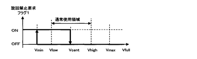
- the arithmetic unit of the control block 105 inputs the corrected capacitor voltage which is the output of the control block 103, and outputs a hydraulic single mode switching request to the switching means 85 of the controller 80 shown in FIG. Switching to the hydraulic single mode is set to be performed based on the storage state of the capacitor 24. When the storage amount is large, a regeneration prohibition flag is output in two stages, and when the storage amount is small, a turn prohibition flag is output in two stages. ing.
- FIG. 10A is a characteristic diagram showing an output example (regeneration prohibition flag setting example) of a hydraulic single mode switching request in an embodiment of the hybrid construction machine of the present invention
- FIG. 10B is an embodiment of the hybrid construction machine of the present invention. It is a characteristic view which shows the output example (turning prohibition flag setting example) of the hydraulic single mode switching request
- 10A and 10B the same reference numerals as those shown in FIGS. 1 to 9 are the same parts, and thus detailed description thereof is omitted.
- the regeneration prohibition request flag is turned on and the mode is switched to the hydraulic only mode. Thereafter, at the stage where the capacitor voltage drops and returns to the median value Vcent of the normal use region due to self-discharge or the like, the regeneration prohibition flag is turned OFF and the hydraulic single mode is released.
- the turning prohibition flag is turned on and the mode is switched to the hydraulic only mode. In this case, the work can be continued in the hydraulic single mode. In order to enable the hydraulic / electric combined control again, it is necessary to charge the charged amount of the capacitor 24 to be within a predetermined range.
- this charging method for example, there are a method in which a separate charging circuit is provided and charging is performed from the outside, and a method in which a predetermined work mode (charging mode) is provided and charging is performed using the swing electric motor 25. A method may be used. Note that the above-described ON / OFF of each flag is switched at the stage when the turning operation and the timing when the operation is not performed are made in order to reduce the shock during the operation as much as possible.
- the second regeneration prohibition flag is turned ON when the capacitor voltage reaches a predetermined voltage value equal to or higher than the threshold value Vmax of the regeneration prohibition region, for example, Vfull.
- the control method of switching can also be taken.
- the state in which the capacitor voltage reaches Vfull is determined to be a case where an abnormality has occurred in the capacitor 24. Therefore, switching from the OFF state to the ON state of the second regeneration prohibition flag indicates whether or not a turning operation is being performed. Regardless of what happens, it takes place immediately.
- switching from the hydraulic / electric combined swing mode to the hydraulic single swing mode is performed in response to the request from the energy management control block 82 described above, and there is an abnormality in the electric system such as the power control unit 55, the swing electric motor 25, the capacitor 24, and the like. It can also be carried out when this occurs. In this case, switching from the hydraulic / electric combined swing mode to the hydraulic single swing mode is performed based on the determination in the abnormality monitoring / abnormal processing block 81.
- the mode switching between the hydraulic / electric combined swing mode and the hydraulic single swing mode may cause a light operation shock due to the switching operation of the valve on the hydraulic circuit at the time of mode switching, an error signal If there is no seriousness and there is no urgency to switch immediately, it is performed when the turning operation and operation are not performed, or when idling is performed when no operation is performed including the front. For abnormalities such as inverter overcurrent that may damage the system or lead to serious failure or disaster, immediately stop the electric system and switch to hydraulic single swing mode even during operation.
- the upper swing body 20 when the drive mode of the upper swing body 20 is switched from the hydraulic / electric combined swing mode to the hydraulic single swing mode when the capacitor voltage reaches the predetermined regeneration prohibition value or the swing prohibition value, the upper swing body 20 is driven. Therefore, high workability can be maintained.
- the control for executing the output by adding the torque of the swing electric motor 25 with respect to the reference value is executed. Can be managed within an appropriate range considering the service life. As a result, it is possible to provide a hybrid construction machine having the operability of the turning operation that does not give a sense of incongruity to the conventional construction machine without increasing the capacity of the capacitor 24 that is a power storage device.
- the swing electric motor 25 when the stored amount of the capacitor 24 as the power storage device reaches a preset regeneration prohibition value or rotation prohibition value, the swing electric motor 25 The driving and braking of the revolving structure 20 are stopped, and the driving and braking of the revolving structure 20 are switched to the system in which only the revolving hydraulic motor 27 is used, so that the construction machine can be continuously operated.
- the addition request output command for the capacitor voltage is set for both driving and braking of the swing electric motor 25, but the present invention is not limited to this. Depending on the system, it may be set only to either driving or braking.
Landscapes
- Engineering & Computer Science (AREA)
- Mining & Mineral Resources (AREA)
- Civil Engineering (AREA)
- General Engineering & Computer Science (AREA)
- Structural Engineering (AREA)
- Power Engineering (AREA)
- Operation Control Of Excavators (AREA)
- Control Of Ac Motors In General (AREA)
Priority Applications (4)
| Application Number | Priority Date | Filing Date | Title |
|---|---|---|---|
| EP12752766.1A EP2682532B1 (de) | 2011-03-01 | 2012-02-27 | Hybridbaumaschine |
| US14/000,241 US8825316B2 (en) | 2011-03-01 | 2012-02-27 | Hybrid-type construction machine |
| CN201280009589.0A CN103384747B (zh) | 2011-03-01 | 2012-02-27 | 混合动力式工程机械 |
| KR1020137019981A KR101886896B1 (ko) | 2011-03-01 | 2012-02-27 | 하이브리드식 건설 기계 |
Applications Claiming Priority (2)
| Application Number | Priority Date | Filing Date | Title |
|---|---|---|---|
| JP2011-044251 | 2011-03-01 | ||
| JP2011044251A JP5562272B2 (ja) | 2011-03-01 | 2011-03-01 | ハイブリッド式建設機械 |
Publications (1)
| Publication Number | Publication Date |
|---|---|
| WO2012118027A1 true WO2012118027A1 (ja) | 2012-09-07 |
Family
ID=46757961
Family Applications (1)
| Application Number | Title | Priority Date | Filing Date |
|---|---|---|---|
| PCT/JP2012/054814 Ceased WO2012118027A1 (ja) | 2011-03-01 | 2012-02-27 | ハイブリッド式建設機械 |
Country Status (6)
| Country | Link |
|---|---|
| US (1) | US8825316B2 (de) |
| EP (1) | EP2682532B1 (de) |
| JP (1) | JP5562272B2 (de) |
| KR (1) | KR101886896B1 (de) |
| CN (1) | CN103384747B (de) |
| WO (1) | WO2012118027A1 (de) |
Cited By (3)
| Publication number | Priority date | Publication date | Assignee | Title |
|---|---|---|---|---|
| CN107002827A (zh) * | 2014-10-30 | 2017-08-01 | 尚帕提·罗摩·拉朱 | 一种kvsv即时能源系统 |
| WO2024202325A1 (ja) * | 2023-03-30 | 2024-10-03 | 株式会社日立建機ティエラ | 建設機械 |
| KR102939112B1 (ko) | 2022-09-27 | 2026-03-13 | 가부시키가이샤 히다치 겡키 티에라 | 전동식 건설 기계 |
Families Citing this family (12)
| Publication number | Priority date | Publication date | Assignee | Title |
|---|---|---|---|---|
| JP5356427B2 (ja) * | 2011-02-03 | 2013-12-04 | 日立建機株式会社 | ハイブリッド式建設機械 |
| JP5562893B2 (ja) * | 2011-03-31 | 2014-07-30 | 住友建機株式会社 | ショベル |
| US9206587B2 (en) | 2012-03-16 | 2015-12-08 | Harnischfeger Technologies, Inc. | Automated control of dipper swing for a shovel |
| JP2014169555A (ja) * | 2013-03-04 | 2014-09-18 | Toshiba Mach Co Ltd | ハイブリッド型駆動装置とそのハイブリッド型駆動装置を搭載した建設機械 |
| KR101471288B1 (ko) * | 2013-05-06 | 2014-12-09 | 현대중공업 주식회사 | 선회밀림방지장치를 구비한 굴삭기 선회장치 |
| JP5992886B2 (ja) * | 2013-08-30 | 2016-09-14 | 日立建機株式会社 | 作業機械 |
| JP6490668B2 (ja) * | 2014-03-31 | 2019-03-27 | 住友建機株式会社 | ショベル |
| JP2016108948A (ja) * | 2014-12-02 | 2016-06-20 | ナブテスコ株式会社 | 駆動装置および建設機械 |
| MX392918B (es) | 2015-05-28 | 2025-03-24 | Joy Global Longview Operations Llc | Maquina de mineria y sistema de almacenamiento de energia para la misma |
| DE102015008038A1 (de) * | 2015-06-23 | 2016-12-29 | Liebherr-Components Biberach Gmbh | Kran sowie Verfahren zu dessen Steuerung |
| CN106655954B (zh) * | 2016-10-28 | 2019-05-31 | 广东美的制冷设备有限公司 | 电容小型化电机驱动系统及其的防过压控制方法、装置 |
| JP6869749B2 (ja) * | 2017-02-27 | 2021-05-12 | 住友建機株式会社 | ショベル |
Citations (3)
| Publication number | Priority date | Publication date | Assignee | Title |
|---|---|---|---|---|
| JP2005237178A (ja) * | 2004-02-23 | 2005-09-02 | Kobelco Contstruction Machinery Ltd | 作業機械の動力源装置 |
| JP2008063888A (ja) | 2006-09-09 | 2008-03-21 | Toshiba Mach Co Ltd | 慣性体の有する運動エネルギを電気エネルギに変換するハイブリッド型建設機械 |
| JP2011036111A (ja) * | 2009-08-05 | 2011-02-17 | Toshiba Mach Co Ltd | ハイブリッド型建設機械における蓄電装置の充電量制御方法および制御装置 |
Family Cites Families (8)
| Publication number | Priority date | Publication date | Assignee | Title |
|---|---|---|---|---|
| JPH0745652Y2 (ja) * | 1990-03-09 | 1995-10-18 | 新キャタピラー三菱株式会社 | 走行速度切換装置 |
| JP2000017692A (ja) * | 1998-07-06 | 2000-01-18 | Hitachi Constr Mach Co Ltd | 自動運転ショベルおよびその運転方法 |
| JP2004340055A (ja) * | 2003-05-16 | 2004-12-02 | Honda Motor Co Ltd | ハイブリッド方式の駆動装置 |
| JP5002004B2 (ja) * | 2007-03-23 | 2012-08-15 | 株式会社小松製作所 | ハイブリッド建設機械の発電制御方法およびハイブリッド建設機械 |
| JP5000430B2 (ja) * | 2007-08-28 | 2012-08-15 | 東芝機械株式会社 | ハイブリッド型作業機械の運転制御方法および同方法を用いた作業機械 |
| KR101268849B1 (ko) * | 2007-12-28 | 2013-05-29 | 스미토모 겐키 가부시키가이샤 | 하이브리드식 건설기계 |
| JP5186690B2 (ja) * | 2008-03-21 | 2013-04-17 | 株式会社小松製作所 | ハイブリッド建設機械における蓄電装置の劣化状態判定方法および装置 |
| JP2013531753A (ja) * | 2010-07-06 | 2013-08-08 | ボルボ コンストラクション イクイップメント アーベー | ハイブリッド式掘削機の馬力制御システム及びその制御方法 |
-
2011
- 2011-03-01 JP JP2011044251A patent/JP5562272B2/ja active Active
-
2012
- 2012-02-27 CN CN201280009589.0A patent/CN103384747B/zh not_active Expired - Fee Related
- 2012-02-27 EP EP12752766.1A patent/EP2682532B1/de not_active Not-in-force
- 2012-02-27 WO PCT/JP2012/054814 patent/WO2012118027A1/ja not_active Ceased
- 2012-02-27 KR KR1020137019981A patent/KR101886896B1/ko not_active Expired - Fee Related
- 2012-02-27 US US14/000,241 patent/US8825316B2/en active Active
Patent Citations (3)
| Publication number | Priority date | Publication date | Assignee | Title |
|---|---|---|---|---|
| JP2005237178A (ja) * | 2004-02-23 | 2005-09-02 | Kobelco Contstruction Machinery Ltd | 作業機械の動力源装置 |
| JP2008063888A (ja) | 2006-09-09 | 2008-03-21 | Toshiba Mach Co Ltd | 慣性体の有する運動エネルギを電気エネルギに変換するハイブリッド型建設機械 |
| JP2011036111A (ja) * | 2009-08-05 | 2011-02-17 | Toshiba Mach Co Ltd | ハイブリッド型建設機械における蓄電装置の充電量制御方法および制御装置 |
Cited By (4)
| Publication number | Priority date | Publication date | Assignee | Title |
|---|---|---|---|---|
| CN107002827A (zh) * | 2014-10-30 | 2017-08-01 | 尚帕提·罗摩·拉朱 | 一种kvsv即时能源系统 |
| CN107002827B (zh) * | 2014-10-30 | 2019-08-30 | 尚帕提·罗摩·拉朱 | 一种kvsv即时能源系统 |
| KR102939112B1 (ko) | 2022-09-27 | 2026-03-13 | 가부시키가이샤 히다치 겡키 티에라 | 전동식 건설 기계 |
| WO2024202325A1 (ja) * | 2023-03-30 | 2024-10-03 | 株式会社日立建機ティエラ | 建設機械 |
Also Published As
| Publication number | Publication date |
|---|---|
| JP5562272B2 (ja) | 2014-07-30 |
| EP2682532A1 (de) | 2014-01-08 |
| EP2682532B1 (de) | 2018-10-31 |
| CN103384747B (zh) | 2016-05-18 |
| EP2682532A4 (de) | 2015-04-22 |
| KR101886896B1 (ko) | 2018-08-08 |
| CN103384747A (zh) | 2013-11-06 |
| KR20140009301A (ko) | 2014-01-22 |
| JP2012180681A (ja) | 2012-09-20 |
| US8825316B2 (en) | 2014-09-02 |
| US20130325269A1 (en) | 2013-12-05 |
Similar Documents
| Publication | Publication Date | Title |
|---|---|---|
| JP5562272B2 (ja) | ハイブリッド式建設機械 | |
| JP5356423B2 (ja) | 旋回体を有する建設機械 | |
| JP5204150B2 (ja) | ハイブリッド式建設機械 | |
| KR101897843B1 (ko) | 하이브리드식 건설 기계 및 이에 사용하는 보조 제어 장치 | |
| JP5356427B2 (ja) | ハイブリッド式建設機械 | |
| JP6247617B2 (ja) | 建設機械 | |
| JPWO2013058325A1 (ja) | ハイブリッド駆動式の油圧作業機械 | |
| JP2015040433A (ja) | 建設機械 | |
| JP5443440B2 (ja) | ハイブリッド式建設機械及びこれに用いるカップリング装置 | |
| JP5487427B2 (ja) | ハイブリッド式建設機械 | |
| JP5037558B2 (ja) | ハイブリッド型建設機械 |
Legal Events
| Date | Code | Title | Description |
|---|---|---|---|
| 121 | Ep: the epo has been informed by wipo that ep was designated in this application |
Ref document number: 12752766 Country of ref document: EP Kind code of ref document: A1 |
|
| ENP | Entry into the national phase |
Ref document number: 20137019981 Country of ref document: KR Kind code of ref document: A |
|
| WWE | Wipo information: entry into national phase |
Ref document number: 14000241 Country of ref document: US |
|
| NENP | Non-entry into the national phase |
Ref country code: DE |