WO2012118203A1 - Procédé pour relier une vitre d'automobile à un point d'échange d'électricité - Google Patents
Procédé pour relier une vitre d'automobile à un point d'échange d'électricité Download PDFInfo
- Publication number
- WO2012118203A1 WO2012118203A1 PCT/JP2012/055456 JP2012055456W WO2012118203A1 WO 2012118203 A1 WO2012118203 A1 WO 2012118203A1 JP 2012055456 W JP2012055456 W JP 2012055456W WO 2012118203 A1 WO2012118203 A1 WO 2012118203A1
- Authority
- WO
- WIPO (PCT)
- Prior art keywords
- lead
- window glass
- supply terminal
- power supply
- free solder
- Prior art date
- Legal status (The legal status is an assumption and is not a legal conclusion. Google has not performed a legal analysis and makes no representation as to the accuracy of the status listed.)
- Ceased
Links
Images



Classifications
-
- B—PERFORMING OPERATIONS; TRANSPORTING
- B23—MACHINE TOOLS; METAL-WORKING NOT OTHERWISE PROVIDED FOR
- B23K—SOLDERING OR UNSOLDERING; WELDING; CLADDING OR PLATING BY SOLDERING OR WELDING; CUTTING BY APPLYING HEAT LOCALLY, e.g. FLAME CUTTING; WORKING BY LASER BEAM
- B23K35/00—Rods, electrodes, materials, or media, for use in soldering, welding, or cutting
- B23K35/22—Rods, electrodes, materials, or media, for use in soldering, welding, or cutting characterised by the composition or nature of the material
- B23K35/24—Selection of soldering or welding materials proper
- B23K35/26—Selection of soldering or welding materials proper with the principal constituent melting at less than 400°C
- B23K35/262—Sn as the principal constituent
-
- B—PERFORMING OPERATIONS; TRANSPORTING
- B23—MACHINE TOOLS; METAL-WORKING NOT OTHERWISE PROVIDED FOR
- B23K—SOLDERING OR UNSOLDERING; WELDING; CLADDING OR PLATING BY SOLDERING OR WELDING; CUTTING BY APPLYING HEAT LOCALLY, e.g. FLAME CUTTING; WORKING BY LASER BEAM
- B23K1/00—Soldering, e.g. brazing, or unsoldering
- B23K1/0008—Soldering, e.g. brazing, or unsoldering specially adapted for particular articles or work
-
- B—PERFORMING OPERATIONS; TRANSPORTING
- B23—MACHINE TOOLS; METAL-WORKING NOT OTHERWISE PROVIDED FOR
- B23K—SOLDERING OR UNSOLDERING; WELDING; CLADDING OR PLATING BY SOLDERING OR WELDING; CUTTING BY APPLYING HEAT LOCALLY, e.g. FLAME CUTTING; WORKING BY LASER BEAM
- B23K35/00—Rods, electrodes, materials, or media, for use in soldering, welding, or cutting
- B23K35/22—Rods, electrodes, materials, or media, for use in soldering, welding, or cutting characterised by the composition or nature of the material
- B23K35/24—Selection of soldering or welding materials proper
- B23K35/26—Selection of soldering or welding materials proper with the principal constituent melting at less than 400°C
-
- C—CHEMISTRY; METALLURGY
- C22—METALLURGY; FERROUS OR NON-FERROUS ALLOYS; TREATMENT OF ALLOYS OR NON-FERROUS METALS
- C22C—ALLOYS
- C22C13/00—Alloys based on tin
-
- C—CHEMISTRY; METALLURGY
- C22—METALLURGY; FERROUS OR NON-FERROUS ALLOYS; TREATMENT OF ALLOYS OR NON-FERROUS METALS
- C22C—ALLOYS
- C22C28/00—Alloys based on a metal not provided for in groups C22C5/00 - C22C27/00
-
- H—ELECTRICITY
- H01—ELECTRIC ELEMENTS
- H01Q—ANTENNAS, i.e. RADIO AERIALS
- H01Q1/00—Details of, or arrangements associated with, antennas
- H01Q1/12—Supports; Mounting means
- H01Q1/1271—Supports; Mounting means for mounting on windscreens
-
- H—ELECTRICITY
- H05—ELECTRIC TECHNIQUES NOT OTHERWISE PROVIDED FOR
- H05B—ELECTRIC HEATING; ELECTRIC LIGHT SOURCES NOT OTHERWISE PROVIDED FOR; CIRCUIT ARRANGEMENTS FOR ELECTRIC LIGHT SOURCES, IN GENERAL
- H05B3/00—Ohmic-resistance heating
- H05B3/84—Heating arrangements specially adapted for transparent or reflecting areas, e.g. for demisting or de-icing windows, mirrors or vehicle windshields
-
- H—ELECTRICITY
- H01—ELECTRIC ELEMENTS
- H01R—ELECTRICALLY-CONDUCTIVE CONNECTIONS; STRUCTURAL ASSOCIATIONS OF A PLURALITY OF MUTUALLY-INSULATED ELECTRICAL CONNECTING ELEMENTS; COUPLING DEVICES; CURRENT COLLECTORS
- H01R4/00—Electrically-conductive connections between two or more conductive members in direct contact, i.e. touching one another; Means for effecting or maintaining such contact; Electrically-conductive connections having two or more spaced connecting locations for conductors and using contact members penetrating insulation
- H01R4/02—Soldered or welded connections
-
- H—ELECTRICITY
- H05—ELECTRIC TECHNIQUES NOT OTHERWISE PROVIDED FOR
- H05B—ELECTRIC HEATING; ELECTRIC LIGHT SOURCES NOT OTHERWISE PROVIDED FOR; CIRCUIT ARRANGEMENTS FOR ELECTRIC LIGHT SOURCES, IN GENERAL
- H05B2203/00—Aspects relating to Ohmic resistive heating covered by group H05B3/00
- H05B2203/016—Heaters using particular connecting means
Definitions
- the present invention relates to a method of joining a metal terminal called a power feeding terminal to an automobile window glass.
- the defogger is composed of a plurality of resistance heating wires disposed horizontally and in parallel over almost the entire surface of the glass plate, and two conductive wires called bus bars for supplying power to the ends of the resistance heating wires. .
- the two bus bars are arranged opposite to the left and right sides of the glass plate, and have a wiring width wider than that of the resistance heating line in order to supply sufficient power to the resistance heating line.
- An electric current is passed between the bus bars, whereby the resistance heating wire generates heat and warms the glass plate, thereby preventing poor visibility due to condensation.
- Such a bus bar is made by screen-printing a silver paste composed of glass frit, silver particles and an organic binder on a glass plate, and then drying and baking it.
- the current is supplied from a power supply terminal soldered to a predetermined location on the bus bar.
- current is taken out from the power supply terminal.
- the power supply terminal and the bus bar are connected by solder containing lead.
- lead is a highly toxic environmental pollutant.
- adverse effects on health, adverse effects and pollution on the environment, especially the ecosystem are regarded as problems. Therefore, there is a strong social demand not to use lead as much as possible.
- Many industries, including the consumer electronics industry have already used low-lead or lead-free solder for various soldering applications. Such a movement is similar to the solder for the vehicle, and the movement to make the solder for the vehicle lead-free is rapidly spreading.
- a ceramic having a black or near-tone color (hereinafter referred to as a black ceramic) opaque layer is formed on the glass plate.
- a black ceramic black or near-tone color
- a paste made of glass frit and pigment is printed on the surface of the glass plate by screen printing in a predetermined shape, dried and fired at 600 ° C. to 700 ° C., and the black ceramic layer adheres firmly to the glass plate. Formed in a state.
- Patent Documents 1 and 2 disclose lead-free solders that do not contain lead, which is a harmful substance, and have sufficient bonding strength to oxide materials such as glass and ceramics.
- Patent Document 3 discloses a vehicle glass panel that pays attention to generation of stress in a glass plate after soldering with a lead-free solder alloy.
- Patent Document 4 discloses an electrical connector for a vehicle window glass plate using solder composed of less than 70 parts of Sn together with a reaction rate adjusting agent larger than 30 parts.
- Patent Document 5 a vehicle window glass plate preheated in a range from a temperature lower by 100 ° C. to a temperature higher by 10 ° C. than the melting point of lead-free solder is used to heat the bonding portion of the terminal and lead the vehicle window by lead-free solder.
- a soldering method for bonding a terminal to a conductor of a glass plate is disclosed.
- Patent Document 6 discloses a lead-free solder composition containing tin, indium, silver and bismuth and a method and apparatus for joining to an automotive glass plate using two types of solder.
- soldering is applied only to the power supply terminal of the automobile window glass, and the automobile window glass and its power supply terminal are joined using a sintered body of silver paste and flux. This method is advantageous in that it is simple and low in cost.
- lead-free solder alloys have been used mainly due to environmental problems.
- a method for soldering only the power supply terminals which is almost the same as the conventional method, has been studied.
- cracks in the solder hardly occur, but cracks tend to occur frequently at the interface between the solder and the sintered silver paste or the interface between the silver paste sintered and the black ceramic.
- Such cracks are likely to occur especially after a cold cycle test or a salt spray test.
- the use of lead-free solder alloys has been strongly demanded by customers, but it has been able to cope only with various limited conditions. In particular, this problem is remarkable in the window glass for automobiles coated with black ceramics.
- composition and method described in Patent Document 6 are epoch-making in that two types of solder are used, but they do not improve the characteristics for the cold cycle test and the salt spray test. Further, in the two types of solder, for example, the upper layer solder is said to have a lower melting temperature than the lower layer solder, and there are some which are difficult to manage during manufacture.
- the present invention has been made in view of the above-described problems, and an object of the present invention is to increase the bonding strength of a power supply terminal made of a lead-free solder alloy, particularly in the case of an automotive window glass coated with black ceramics.
- the present invention is a method for soldering a window glass and a power supply terminal with a lead-free solder alloy through a conductive wire made of a sintered body of a silver paste formed by coating on the surface of an automotive window glass, A first step of forming a solder layer by heat-welding to a predetermined location on a conductive wire using a lead-free solder alloy used for soldering a window glass and a power supply terminal; A second step of forming a solder layer by heat-welding to the terminal seat of the power supply terminal; A third step of aligning the solder layer formed in the first step and the surface of the solder layer formed in the second step; A fourth step in which both solder layers are heated with a heater with a controlled heating temperature, and both solder layers are welded together and joined together; This is a method (first method) for joining an automotive window glass and a power supply terminal, characterized by comprising a fifth step of cooling by controlling the cooling rate.
- the first method may be a method of joining the window glass for an automobile and its power supply terminal (second method) in which the thickness of the solder layer in the first step is 0.2 mm or more and 3 mm or less.
- the first or second method is a joining method (third method) of an automotive window glass and its power supply terminal, wherein the heat welding temperature of the lead-free solder alloy in the first step is not lower than the melting point and not higher than the melting point + 100 ° C. Also good.
- Any one of the first to third methods is a joining method (fourth method) of an automotive window glass and its power supply terminal, in which the lead-free solder alloy is heat-welded in the first step using ultrasonic waves. There may be.
- any one of the first to fourth methods is a method of joining an automotive window glass and its power supply terminal (fifth), wherein the thickness of the solder layer in the second step is not less than 0.5 mm and not more than 5 mm. Method).
- any one of the first to fourth methods is a joining method (sixth method) of an automotive window glass and its power feeding terminal, wherein the joining temperature in the fourth step is not lower than the melting point and not higher than the melting point + 100 ° C. Also good.
- the cooling rate after joining in the fifth step is controlled by cooling at a cooling rate of 5.0 ° C./sec or more by blowing air.
- the window glass and its power feeding terminal joining method (seventh method) may be used.
- Any one of the first to seventh methods includes: an automotive window glass having a black ceramic layer, and a sintered body of silver paste is heat-welded on the black ceramic layer.
- a joining method (eighth method) of glass and its power supply terminal may be used.
- Any one of the first to eighth methods may be a method for joining an automotive window glass and its power supply terminal (the ninth method) in which the lead-free solder alloy is In-Ag-Sn solder.
- Any one of the first to eighth methods may be a method of joining an automotive window glass and its power supply terminal (tenth method), in which the lead-free solder alloy is Sn—Ag—Cu solder.
- a part of the lead-free solder alloy used for joining the window glass and the power supply terminal is previously deposited on the silver paste sintered body, and the lead-free solder alloy is heat-welded to the silver paste sintered body.
- heat-welding is also performed on a power supply terminal for an automobile window glass using a part of the lead-free solder alloy.
- solder layer surfaces of both the power supply terminal and the window glass, on which the solder layer is separately formed in advance are aligned in the third step, and both the solder layers are heated and welded together in the fourth step.
- this fourth step it is only necessary to heat both solder layers and weld and bond the two solder layers, and if the surfaces of both solder layers are welded, sufficient adhesive strength can be obtained. ), The bonding strength is maintained without remelting the interface between the window glass and the solder layer heat-welded in the first step and the interface between the power supply terminal and the solder layer heat-welded in the second step. .
- the order of the first step and the second step is not limited. Further, it is desirable that the solder alloys used in the first step and the second step have the same composition. That is, two types of lead-free solder alloys are not fused to bond the solders together, but may be joined using the same lead-free solder alloy. It is quite difficult to successfully fuse two types of lead-free solder alloys having very different compositions, and an interface may occur between the two types of lead-free solder alloys. When such an interface occurs, a problem of heat shrinkage occurs on the interface, or salt water enters. Therefore, if the alloy composition does not cause such an interface to reduce the bonding strength, the solder composition used in the first step and the second step may be slightly different or an improved component may be added. Good.
- the bonding strength was measured according to JIS C60068. Measured by bending the connection part of the power supply terminal after the thermal cycle test and salt spray test so as to be perpendicular to the terminal seat, and pulling the connection part in a direction perpendicular to the joint surface using a push-pull gauge. When the power supply terminal was not peeled off, it was determined that the adhesive strength was good.
- the joining strength can be increased.
- a thermal cycle test and salt water that reproduces the situation where glass with lead terminals joined using lead-free solder alloy is held for a long time in a harsh environment against solder in areas where the temperature difference between day and night is large or near the coast. Even after the spray test, the bonding strength of the power supply terminal to the glass with the lead-free solder alloy can be sufficiently maintained.
- FIG. 8 is a cross-sectional view taken along the line aa ′ of FIG.
- the present invention relates to a method of joining a conductive wire of a window glass for an automobile and a feeding terminal with a lead-free solder alloy.
- the conductive wire is formed of a silver paste sintered body.
- a lead-free solder alloy is heat-welded on the silver paste sintered body to form a solder layer.
- a lead-free solder alloy is heat-welded to the terminal seat of the power supply terminal to form a solder layer.
- the solder layer formed in the first step and the surface of the solder layer formed in the second step are aligned.
- both the solder layers are heated by a heater whose heating temperature is controlled, and both the solder layers are welded and bonded together.
- the cooling rate is controlled to quench.
- FIG. 2 is a conceptual cross-sectional view showing a state in which a power supply terminal is joined to a predetermined location on a glass bar bus bar by a conventional method.
- the glass plate 1, the black ceramic layer 2, the silver paste sintered body 3 and the power supply terminal 6 are joined by solder 5. Further, when the power supply terminal 6 is viewed in large size, the power supply terminal 6 includes a connection portion 10 with an external power supply element and a power supply terminal seat 11 attached to the glass plate. In general, the power supply terminal 11 has two seats, but there may be one or three or more.
- FIG. 1 is a conceptual cross-sectional view showing a state in which a feeding terminal is joined to a predetermined location on a glass plate bus bar by the method of the present invention.
- a black ceramic layer 2 is disposed on the glass plate 1.
- the black ceramic paste is applied on the glass plate 1 and then dried. Further, a silver paste is applied and dried on the dried black ceramic paste. Furthermore, it is common that the black ceramic paste and the silver paste are simultaneously sintered and strengthened in a glass strengthening furnace.
- the lead-free solder alloy layer 4 applied in the first step and the lead-free solder alloy layer 5 applied in the second step coexist.
- the power supply terminal 6 is on the lead-free solder alloy layer 5 applied in the second step.
- the power supply terminal 6 is often made of brass, but the material is not limited. Although the general shape of the power supply terminal 6 is shown in FIG. 1, the shape of the power supply terminal is many and is not limited to this shape.
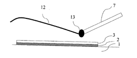
- FIG. 3 is a view showing a state in which a lead-free solder alloy 4 is heated and welded by a soldering iron (heater) 7 on a sintered body of silver paste placed on black ceramics in the first step.
- FIG. 3 is a view showing a state in which a lead-free solder alloy 4 is heated and welded by a soldering iron (heater) 7 on a sintered body of silver paste placed on black ceramics in the first step.
- FIG. 4 is a conceptual diagram of the present invention showing a state in which a power feeding terminal for an automobile window glass and an automobile window glass are joined in the fourth step.
- the lead-free solder alloy heat-welded in the first step and the second step heats both solder layers with a heater 9 or the like at a temperature not lower than the melting point and not higher than the melting point + 50 ° C. for not shorter than 3 seconds and not longer than 30 seconds.
- air is blown at a cooling rate of 5.0 ° C./sec or more to cool to room temperature.
- lead-free solder alloys are harder than leaded solder alloys and do not easily deform.
- Sn—Ag—Cu lead-free solder is not easily deformed because it is surrounded by a eutectic structure composed of an intermetallic compound of Ag 3 Sn and Cu 6 Sn 5 that is difficult to deform around the Sn crystal. .
- this eutectic structure cannot prevent the deformation and the deformation starts, the deformability until the breakage is low, and therefore, the eutectic structure is easily broken. Therefore, in order to stabilize the mechanical properties of the Sn—Ag—Cu lead-free solder, it is necessary to control the metal structure.
- the molten Sn—Ag—Cu lead-free solder is rapidly cooled to suppress the growth of Sn crystals, reduce the crystal size as much as possible, and quickly precipitate the eutectic structure. Due to the rapid cooling, the Sn crystal and the eutectic structure become a finely mixed metal structure, and the eutectic structure that prevents deformation is dispersed, so that the ability to prevent deformation is reduced, the deformation is easily deformed, and the deformability up to fracture is reduced. Due to the large structure, the mechanical properties can be stabilized.
- the cooling rate in the fifth step is preferably 5.0 ° C./sec or more. The more rapidly cooled, the finer the solder structure. When the cooling rate is smaller than this, the metal structure of the lead-free solder alloy is not stable, the toughness of the solder is lowered, and sufficient bonding strength cannot be obtained.
- the cooling rate is more preferably 6.0 ° C./sec or more. More preferably, it is 7.0 ° C./sec or more.
- the thickness of the lead-free solder alloy in the first step is 0.2 mm or more and 3 mm or less. If the thickness is less than 0.2 mm, a problem that good bonding strength cannot be obtained occurs. On the other hand, when it exceeds 3 mm, the problem which looks worse arises. More preferably, the thickness is 0.3 mm to 2 mm, and still more preferably 0.4 mm to 1.5 mm. In addition, about lead-free solder alloy, it does not necessarily become a uniform thickness in all, but since the area differs somewhat, it is better to interpret the above-mentioned value as an average value.
- the heat welding temperature of the lead-free solder alloy in the first step is not lower than the melting point and not higher than the melting point + 100 ° C. If the temperature is lower than the melting point, a problem that the lead-free solder alloy does not melt occurs. On the other hand, when the melting point exceeds + 100 ° C., fine cracks and the like are generated on the glass plate, and as a result, there is a problem that good bonding strength cannot be obtained. Furthermore, since time is required for cooling, the problem that production efficiency falls arises.
- it is melting
- the melting point is measured by a general differential thermal analyzer.
- the lead-free solder alloy is heat-welded in the first step using an ultrasonic soldering iron.
- an ultrasonic soldering iron By using an ultrasonic soldering iron, the bonding strength of the silver paste with the sintered body can be further increased.
- the application time of ultrasonic waves be 0.5 seconds or more and 20 seconds or less. If the time is less than 0.5 seconds, a problem that good bonding strength cannot be obtained occurs. On the other hand, if it exceeds 20 seconds, the characteristics of the sintered body of the silver paste change, and it may not be possible to join the lead-free solder alloy. More preferably, they are 1 second or more and 15 seconds or less, More preferably, they are 2 seconds or more and 10 seconds or less.
- the lead-free solder alloy in the second step has a thickness of 0.5 mm to 5 mm. If the thickness is less than 0.5 mm, a problem that good bonding strength cannot be obtained occurs. On the other hand, when it exceeds 5 mm, the problem which looks worse arises. More preferably, it is 0.8 mm or more and 4 mm or less, More preferably, it is 1 mm or more and 3 mm or less.
- the relative positions of the two solder layers are aligned and fixed using a positioning jig or the like.
- the bonding temperature in the fourth step is not less than the melting point and not more than the melting point + 50 ° C. If the temperature is lower than the melting point, a problem that the lead-free solder alloy does not melt occurs. On the other hand, when the melting point exceeds + 50 ° C., fine cracks and the like are generated on the glass plate. In addition, it takes time to cool the lead-free solder alloy, and the eutectic structure that prevents deformation of the lead-free solder alloy is not dispersed, so the deformation prevention ability is improved, the structure is difficult to deform, and the deformability until breakage is reduced. By doing so, the mechanical properties become unstable, resulting in a problem that good bonding strength cannot be obtained.
- the melting point is not lower than the melting point and not higher than the melting point + 40 ° C., and further preferably not lower than the melting point and not higher than the melting point + 30 ° C.
- the soldering is performed in advance on the terminal seat of the power supply terminal and the predetermined position on the conductive wire of the window glass of the automobile. For this reason, heat is easily transmitted to the solder, and even if the heating temperature is lowered, the bonding strength is exhibited. For example, a predetermined adhesive strength can be obtained even at a temperature of melting point + 30 ° C. or lower.
- the window glass for automobile has a black ceramic layer and a sintered body of silver paste is heat-welded on the black ceramic layer.
- the window glass for automobiles having a black ceramic layer has a higher temperature in a portion where the black ceramic paste is applied in a heating process during processing than in other portions. Therefore, when the sintered body of the silver paste is present on the black ceramic layer, the silver paste is overfired more than usual during the sintering, and the adhesive strength with the power supply terminal tends to be small.
- solder alloy there is an In—Ag—Sn solder. Further, the desirable composition thereof will be described below. In-Ag—Sn solder composed of 26% by weight to 56% by weight In, 0.1% by weight to 5% by weight Ag, and the balance of Sn. . If In is less than 26% by weight, the Young's modulus increases, and the glass plate may be cracked. On the other hand, if In exceeds 56% by weight, the adhesive strength of the lead-free solder alloy is reduced due to residual internal stress due to the phase change of In 3 Sn / In 3 Sn + InSn 4 and the occurrence of cracks even at a temperature change near room temperature. More preferably, it is 28 to 54 weight%.
- the amount of Ag added in the present invention is preferably 0.1% by mass or more and 5% by mass or less.
- a defogger heat wire and an antenna wire are formed by screen printing-drying-firing silver paste, and a power supply terminal that contacts the silver wire and the vehicle body is connected by a lead-free solder alloy.
- a lead-free solder alloy In order to prevent silver wire corrosion (so-called silver erosion) by the lead-free solder alloy, it is effective to add Ag to the lead-free solder alloy.
- these effects are low, and if it exceeds 5% by mass, coarse Ag 3 Sn precipitates, which causes a decrease in strength and fatigue strength.
- they are 0.5 weight% or more and 3 weight% or less, More preferably, they are 0.8 weight% or more and 2 weight% or less.
- the melting point is preferably 90 ° C. or higher and 200 ° C. or lower.
- a lead-free solder alloy of less than 90 ° C. cannot be easily obtained.
- it exceeds 200 ° C. there arises a problem that the bonding strength is lowered. More preferably, it is 95 degreeC or more and 180 degrees C or less, More preferably, it is 100 degreeC or more and 160 degrees C or less. However, it is not necessarily limited to these conditions.
- Sn-Ag-Cu solder is another desirable lead-free solder alloy. Further, the desirable composition thereof will be described below. Sn—Ag composed of 94 wt% to 97 wt% Sn, 2 wt% to 5 wt% Ag, and 0.5 wt% to 2 wt% Cu. -Cu solder.
- Sn is less than 94% by weight, there arises a problem that basic characteristics as a lead-free solder alloy are deteriorated.
- it exceeds 97% by weight there arises a problem that the bonding strength becomes weak. More preferably, they are 94.5 weight% or more and 96.5 weight% or less.
- the lead-free solder alloy becomes hard and brittle, which causes a problem that the bonding strength is lowered. More preferably, they are 0.7 weight% or more and 1.8 weight% or less, More preferably, they are 0.8 weight% or more and 1.7 weight% or less.
- the melting point of Sn—Ag—Cu solder is almost limited to 210 ° C. or higher and 230 ° C. or lower.
- the cold cycle test the salt spray test
- the adhesive strength test refer to the following tests. The details will be described below.
- Salt spray test A salt spray test according to JIS Z2371 was conducted. That is, a 5% NaCl aqueous solution was continuously sprayed at a spraying pressure of 0.1 MPa for 100 hours in an atmosphere at 35 ° C., and the bonding strength after the test was measured.
- Bonding strength test This was performed according to JIS C60068. Bonding strength is measured by bending the connecting part of the power supply terminal so that it is perpendicular to the terminal seat and pulling the connecting part in a direction perpendicular to the joint surface using a push-pull gauge. Those that did not peel off were determined to have good adhesive strength.
- Example 1 First, after applying a black ceramic paste comprising a low melting point glass frit mainly composed of Bi-based borosilicate glass, a black inorganic pigment, an inorganic filler, and a solvent mainly composed of pine oil to a glass plate sample, it is once dried, On top of that, a silver paste composed of a fine melting point of silver particles, a low melting point glass frit mainly composed of Bi-based borosilicate glass, and a solvent mainly composed of terpineol is applied, and after drying, heated to 700 ° C. in a glass strengthening furnace. Then, the paste was fired and the glass plate was tempered simultaneously by rapid cooling. In this way, a tempered glass plate sample similar to a commercially available automobile window glass provided with a sintered body of silver paste was prepared.
- a black ceramic paste comprising a low melting point glass frit mainly composed of Bi-based borosilicate glass, a black inorganic pigment, an inorganic filler, and a solvent mainly
- a general flux was thinly spread on the sintered body of silver paste. Thereafter, about 0.3 g (weight per one place) of a lead-free solder alloy having a diameter of 1.6 mm manufactured in a thread shape was melted and thickened to a thickness of about 1.5 mm on the sintered body of the silver paste.
- the thread-shaped lead-free solder alloy 12 is a lead-free solder alloy 13 in a molten state at the tip of the soldering iron 7.
- the composition of the lead-free solder alloy used here was 51% by weight of In, 1% by weight of Ag, 48% by weight of Sn, and its melting point was 115 ° C.
- the melting point was measured according to JIS Z3198-1, and was measured using a differential type differential thermal balance TG8120 manufactured by Rigaku Corporation. Further, the lead-free solder alloy was heated for about 5 seconds on the sintered body of the silver paste, and was deposited on the sintered body of the silver paste. The temperature of the soldering iron was adjusted so that the lead-free solder alloy temperature was a predetermined temperature.
- the terminals and the glass plate are fixed with clips by aligning the positions of the respective solder layers heated and welded in the first step and the second step, and as a fourth step, the temperature of the lead-free solder alloy is about 140. 4.
- Heater (Stainnel Co., Ltd.) adjusted to 0 ° C. is applied for 8 seconds to heat both solder layers and weld and bond the two solder layers, and then, as a fifth step, air is blown. It cooled to 30 degreeC with the cooling rate of 0 degreeC / sec.
- the temperature of the lead-free solder alloy at this time was measured using a data logger AM-7012L manufactured by Anritsu Keiki Co., Ltd., with a thermocouple installed in the vicinity of the lead-free solder alloy.
- the initial bonding strength of the five power supply terminals bonded in this way was measured. As a result, it was confirmed that all values exceeding 80N required in the market were exceeded.
- Example 2 A tempered glass plate sample almost the same as in Example 1 was prepared. As a first step, a general flux was thinly spread on the sintered body of the silver paste. Thereafter, about 0.03 g (weight per one place) of a lead-free solder alloy having a diameter of 1.6 mm produced in a thread shape was melted and deposited on the silver paste sintered body to a thickness of about 0.4 mm.
- the composition of the lead-free solder alloy used here is 95.2% by weight of Sn, 3.8% by weight of Ag, 1% by weight of Cu, and its melting point is 215 ° C.
- the total amount of lead-free solder alloy in the first step and the second step is about 0.23 g per location, and the ratio of the amount of lead-free solder alloy in the first step to the amount of lead-free solder alloy in the second step is about It was 0.2.
- the terminals and the glass plate are fixed with clips by aligning the positions of the solder layers heated and welded in the first step and the second step, and in the fourth step, the lead-free solder alloy temperature is about 230 ° C.
- the solder layers made by Steinel
- air was blown to 5.0 It cooled to 30 degreeC with the cooling rate of (degreeC) / sec.
- the temperature of the lead-free solder alloy at this time was measured using a data logger AM-7012L manufactured by Anritsu Keiki Co., Ltd., with a thermocouple installed in the vicinity of the lead-free solder alloy.
- the initial bonding strength of the five power supply terminals bonded in this way was measured. As a result, it was confirmed that it exceeded all 80N values required in the market.
- Example 3 A tempered glass plate sample almost the same as in Example 1 was prepared.
- a general flux was thinly spread on the sintered body of the silver paste.
- an ultrasonic soldering iron manufactured by Eishin Kogyo Co., Ltd., melt about 0.3 g of lead-free solder alloy with a diameter of 1.6 mm (weight per part) on the silver paste sintered body while melting it. The height was about 1.5 mm.
- ultrasonic waves were oscillated for about 2 seconds.
- the composition of the lead-free solder alloy used here was 51% by weight of In, 1% by weight of Ag, 48% by weight of Sn, and its melting point was 115 ° C.
- the initial bonding strength of the five power supply terminals bonded in this way was measured. As a result, it was confirmed that it exceeded all 80N values required in the market.
- Example 1 A glass plate sample produced under substantially the same conditions as in Example 1 was prepared.
- a lead-free solder alloy having the same composition as in Example 1 was used. Further, the same soldering iron as in Example 1 was used. Moreover, it performed by what is called the conventional method of performing only by Step 2 without dividing Step 1 and Step 2. At this time, the amount of the lead-free solder alloy was about 0.55 g per one place.
- Other conditions were the same as in Example 1.
- the initial bonding strength of the five power supply terminals bonded in this way was measured. As a result, it was confirmed that it exceeded all 80N values required in the market.
- Example 2 A glass plate sample produced under substantially the same conditions as in Example 2 was prepared.
- the lead-free solder alloy a lead-free solder alloy having the same composition as in Example 2 was used. Moreover, it performed by what is called the conventional method of performing only by Step 2 without dividing Step 1 and Step 2. At this time, the amount of the lead-free solder alloy was about 0.43 g per one place. Other conditions were the same as in Example 2.
- the initial bonding strength of the five power supply terminals bonded in this way was measured. As a result, one sample out of five samples was less than 80N with respect to 80N which is a value required in the market.
- Examples 1, 2, and 3 of the present invention were all good, with bonding strengths exceeding 80 N immediately after soldering, after the thermal cycle test and after the salt spray test.
- Comparative Examples 1 and 2 soldered only in Step 2 without separating Step 1 and Step 2, there is a sample whose adhesive strength immediately after soldering, after the thermal cycle test and after the salt spray test is less than 80N. It was not good.
Landscapes
- Engineering & Computer Science (AREA)
- Mechanical Engineering (AREA)
- Chemical & Material Sciences (AREA)
- Materials Engineering (AREA)
- Metallurgy (AREA)
- Organic Chemistry (AREA)
- Joining Of Glass To Other Materials (AREA)
- Surface Treatment Of Glass (AREA)
- Manufacturing Of Electrical Connectors (AREA)
- Connections Effected By Soldering, Adhesion, Or Permanent Deformation (AREA)
- Details Of Aerials (AREA)
Abstract
L'invention porte sur un procédé qui sert à relier une vitre d'automobile à un point d'échange d'électricité, et qui comprend : une première étape, dans laquelle, à l'aide d'un alliage de soudure sans plomb, une couche de soudure est formée par thermosoudage en un emplacement prédéterminé sur un fil conducteur formé sur la surface de la vitre d'automobile ; une deuxième étape consistant à former une couche de soudure par thermosoudage au siège de borne du point d'échange d'électricité ; une troisième étape consistant à positionner la surface de la couche de soudure formée dans la deuxième étape à la couche de soudure formée dans la première étape ; une quatrième étape consistant à chauffer encore les deux couches de soudure à l'aide d'un élément chauffant ayant une température de chauffage régulée, de façon à souder et à réunir ainsi les deux couches de soudure l'une à l'autre ; et une cinquième étape consistant à effectuer un refroidissement par commande de la température de refroidissement.
Applications Claiming Priority (2)
| Application Number | Priority Date | Filing Date | Title |
|---|---|---|---|
| JP2011-045780 | 2011-03-02 | ||
| JP2011045780A JP2014096198A (ja) | 2011-03-02 | 2011-03-02 | 自動車用窓ガラスと給電端子の接合方法 |
Publications (1)
| Publication Number | Publication Date |
|---|---|
| WO2012118203A1 true WO2012118203A1 (fr) | 2012-09-07 |
Family
ID=46758127
Family Applications (1)
| Application Number | Title | Priority Date | Filing Date |
|---|---|---|---|
| PCT/JP2012/055456 Ceased WO2012118203A1 (fr) | 2011-03-02 | 2012-03-02 | Procédé pour relier une vitre d'automobile à un point d'échange d'électricité |
Country Status (2)
| Country | Link |
|---|---|
| JP (1) | JP2014096198A (fr) |
| WO (1) | WO2012118203A1 (fr) |
Cited By (10)
| Publication number | Priority date | Publication date | Assignee | Title |
|---|---|---|---|---|
| WO2015045548A1 (fr) * | 2013-09-30 | 2015-04-02 | 日本板硝子株式会社 | Corps structurel de borne et corps de verre de véhicule |
| CN105189003A (zh) * | 2013-03-13 | 2015-12-23 | 日本斯倍利亚社股份有限公司 | 焊剂接合物及焊剂接合方法 |
| JP2016096195A (ja) * | 2014-11-12 | 2016-05-26 | 富士通株式会社 | 電子装置及び電子装置の製造方法 |
| CN108598736A (zh) * | 2018-04-10 | 2018-09-28 | 武汉武耀安全玻璃股份有限公司 | 无铅型汽车玻璃接线端子 |
| CN109759742A (zh) * | 2019-03-13 | 2019-05-17 | 重庆理工大学 | 一种无钎焊剂用的焊料及焊接方法 |
| EP3458222A4 (fr) * | 2016-05-20 | 2020-03-25 | Saint-Gobain Glass France | Procédé de brasage résistif, ensemble antenne et verre, et système de brasage résistif |
| US10696582B2 (en) | 2016-01-22 | 2020-06-30 | Central Glass Co., Ltd. | Vehicle window glass and method for manufacturing vehicle window glass |
| US20210001432A1 (en) * | 2018-03-22 | 2021-01-07 | Central Glass Company, Limited | Method of producing a vehicle glass assembly |
| US20230339034A1 (en) * | 2022-04-22 | 2023-10-26 | Magna Exteriors, Inc. | Vehicular window assembly process with temperature control of the solder joint that attaches an electrical connector |
| US12224540B2 (en) * | 2019-07-01 | 2025-02-11 | Nippon Sheet Glass Company, Limited | Connection terminal |
Families Citing this family (6)
| Publication number | Priority date | Publication date | Assignee | Title |
|---|---|---|---|---|
| CN104010391B (zh) * | 2014-05-28 | 2015-11-18 | 中山市新纪元电器有限公司 | 一种壶胆装置的连接方法及由该方法制成的壶胆装置 |
| EP3696916B1 (fr) | 2017-11-07 | 2022-07-13 | Central Glass Company, Limited | Ensemble vitre de fenêtre de voiture |
| JP7450843B2 (ja) | 2018-09-07 | 2024-03-18 | セントラル硝子プロダクツ株式会社 | 車両窓用ガラスアッセンブリー |
| JP7274279B2 (ja) * | 2018-11-05 | 2023-05-16 | Agc株式会社 | 金属端子付きガラス板の製造方法 |
| CN113412173B (zh) * | 2019-02-08 | 2023-02-17 | 日本板硝子株式会社 | 玻璃板组件 |
| JP2020037404A (ja) * | 2019-10-25 | 2020-03-12 | セントラル硝子株式会社 | 車両用窓ガラス |
Citations (11)
| Publication number | Priority date | Publication date | Assignee | Title |
|---|---|---|---|---|
| JPH07105723A (ja) * | 1993-08-31 | 1995-04-21 | Cerdec Ag Keramische Farben | 銀含有電導性コーティング組成物、銀含有電導性コーティング、銀含有電導性コーティングの製造法およびコーティングされた支持体 |
| JPH09260829A (ja) * | 1996-03-27 | 1997-10-03 | Fujikura Ltd | フラットケーブルの半田接続方法 |
| JP2000141078A (ja) * | 1998-09-08 | 2000-05-23 | Nippon Sheet Glass Co Ltd | 無鉛ハンダ |
| JP2000326088A (ja) * | 1999-03-16 | 2000-11-28 | Nippon Sheet Glass Co Ltd | 無鉛ハンダ |
| JP2003521093A (ja) * | 2000-01-25 | 2003-07-08 | ソシエタ イタリアーナ ベトロ − エスアイブイ − ソシエタ ペル アチオニ | 電気端子を有するグレイジング |
| JP2006523917A (ja) * | 2003-01-30 | 2006-10-19 | ピルキントン パブリック リミテッド カンパニー | 車両用ガラスパネル |
| JP2008218399A (ja) * | 2007-01-02 | 2008-09-18 | Agc Automotive Americas R & D Inc | 車両の窓ガラス用の電気コネクタ |
| JP2009504411A (ja) * | 2005-08-12 | 2009-02-05 | アンタヤ・テクノロジーズ・コーポレーション | はんだ組成物 |
| JP2009509767A (ja) * | 2005-08-12 | 2009-03-12 | インテル コーポレイション | バルク金属ガラス製はんだ |
| JP2009199746A (ja) * | 2008-02-19 | 2009-09-03 | Murakami Corp | 発熱ガラスおよびその製造方法 |
| JP2010154504A (ja) * | 2008-11-20 | 2010-07-08 | Asahi Glass Co Ltd | 車両用ガラスアンテナ及び車両用窓ガラス |
-
2011
- 2011-03-02 JP JP2011045780A patent/JP2014096198A/ja not_active Withdrawn
-
2012
- 2012-03-02 WO PCT/JP2012/055456 patent/WO2012118203A1/fr not_active Ceased
Patent Citations (11)
| Publication number | Priority date | Publication date | Assignee | Title |
|---|---|---|---|---|
| JPH07105723A (ja) * | 1993-08-31 | 1995-04-21 | Cerdec Ag Keramische Farben | 銀含有電導性コーティング組成物、銀含有電導性コーティング、銀含有電導性コーティングの製造法およびコーティングされた支持体 |
| JPH09260829A (ja) * | 1996-03-27 | 1997-10-03 | Fujikura Ltd | フラットケーブルの半田接続方法 |
| JP2000141078A (ja) * | 1998-09-08 | 2000-05-23 | Nippon Sheet Glass Co Ltd | 無鉛ハンダ |
| JP2000326088A (ja) * | 1999-03-16 | 2000-11-28 | Nippon Sheet Glass Co Ltd | 無鉛ハンダ |
| JP2003521093A (ja) * | 2000-01-25 | 2003-07-08 | ソシエタ イタリアーナ ベトロ − エスアイブイ − ソシエタ ペル アチオニ | 電気端子を有するグレイジング |
| JP2006523917A (ja) * | 2003-01-30 | 2006-10-19 | ピルキントン パブリック リミテッド カンパニー | 車両用ガラスパネル |
| JP2009504411A (ja) * | 2005-08-12 | 2009-02-05 | アンタヤ・テクノロジーズ・コーポレーション | はんだ組成物 |
| JP2009509767A (ja) * | 2005-08-12 | 2009-03-12 | インテル コーポレイション | バルク金属ガラス製はんだ |
| JP2008218399A (ja) * | 2007-01-02 | 2008-09-18 | Agc Automotive Americas R & D Inc | 車両の窓ガラス用の電気コネクタ |
| JP2009199746A (ja) * | 2008-02-19 | 2009-09-03 | Murakami Corp | 発熱ガラスおよびその製造方法 |
| JP2010154504A (ja) * | 2008-11-20 | 2010-07-08 | Asahi Glass Co Ltd | 車両用ガラスアンテナ及び車両用窓ガラス |
Cited By (17)
| Publication number | Priority date | Publication date | Assignee | Title |
|---|---|---|---|---|
| CN105189003A (zh) * | 2013-03-13 | 2015-12-23 | 日本斯倍利亚社股份有限公司 | 焊剂接合物及焊剂接合方法 |
| EP2974818A4 (fr) * | 2013-03-13 | 2016-09-28 | Nihon Superior Co Ltd | Alliage de soudure et joint à base de ce dernier |
| JPWO2014142153A1 (ja) * | 2013-03-13 | 2017-02-16 | 株式会社日本スペリア社 | はんだ接合物及びはんだ接合方法 |
| WO2015045548A1 (fr) * | 2013-09-30 | 2015-04-02 | 日本板硝子株式会社 | Corps structurel de borne et corps de verre de véhicule |
| JP2015069893A (ja) * | 2013-09-30 | 2015-04-13 | 日本板硝子株式会社 | 端子構造体及び車両用のガラス体 |
| JP2016096195A (ja) * | 2014-11-12 | 2016-05-26 | 富士通株式会社 | 電子装置及び電子装置の製造方法 |
| US10696582B2 (en) | 2016-01-22 | 2020-06-30 | Central Glass Co., Ltd. | Vehicle window glass and method for manufacturing vehicle window glass |
| EP3458222A4 (fr) * | 2016-05-20 | 2020-03-25 | Saint-Gobain Glass France | Procédé de brasage résistif, ensemble antenne et verre, et système de brasage résistif |
| US11298767B2 (en) | 2016-05-20 | 2022-04-12 | Saint-Gobain Glass France | Resistive soldering method, assembly of antenna and glass, and resistive soldering system |
| US20210001432A1 (en) * | 2018-03-22 | 2021-01-07 | Central Glass Company, Limited | Method of producing a vehicle glass assembly |
| US12091729B2 (en) * | 2018-03-22 | 2024-09-17 | Acr Ii Glass America Inc. | Method of producing a vehicle glass assembly |
| CN108598736A (zh) * | 2018-04-10 | 2018-09-28 | 武汉武耀安全玻璃股份有限公司 | 无铅型汽车玻璃接线端子 |
| CN109759742A (zh) * | 2019-03-13 | 2019-05-17 | 重庆理工大学 | 一种无钎焊剂用的焊料及焊接方法 |
| CN109759742B (zh) * | 2019-03-13 | 2024-03-26 | 重庆理工大学 | 一种无钎焊剂用的焊料及焊接方法 |
| US12224540B2 (en) * | 2019-07-01 | 2025-02-11 | Nippon Sheet Glass Company, Limited | Connection terminal |
| US20230339034A1 (en) * | 2022-04-22 | 2023-10-26 | Magna Exteriors, Inc. | Vehicular window assembly process with temperature control of the solder joint that attaches an electrical connector |
| US12269127B2 (en) * | 2022-04-22 | 2025-04-08 | Magna Exteriors, Inc. | Vehicular window assembly process with temperature control of the solder joint that attaches an electrical connector |
Also Published As
| Publication number | Publication date |
|---|---|
| JP2014096198A (ja) | 2014-05-22 |
Similar Documents
| Publication | Publication Date | Title |
|---|---|---|
| WO2012118203A1 (fr) | Procédé pour relier une vitre d'automobile à un point d'échange d'électricité | |
| JP6928062B2 (ja) | 無鉛はんだ組成物の製造方法 | |
| JP3957302B2 (ja) | 金具が接合されたガラス物品、およびこれを用いた接合構造 | |
| CN100546757C (zh) | 导电性填料和焊料 | |
| JP7082641B2 (ja) | インジウム-スズ-銀ベースの無鉛はんだ | |
| CN104540636B (zh) | 具有电连接元件的玻璃板 | |
| TW201615854A (zh) | 用於焊料層次的低溫高可靠度合金 | |
| US20130333929A1 (en) | Terminal Structure for Glass Plate with Conductive Section and Glass Plate Article Utilizing Same | |
| TW201431636A (zh) | 無鉛焊料合金 | |
| JP6106801B2 (ja) | はんだ付け方法及び自動車用ガラス | |
| JP2012091216A (ja) | 無鉛はんだ合金、およびこれを用いたガラス物品 | |
| CN103402695B (zh) | 车辆玻璃用无铅焊料合金 | |
| JP7450843B2 (ja) | 車両窓用ガラスアッセンブリー | |
| CN103586595B (zh) | 用于玻璃的无铅焊料组合物 | |
| CN100494436C (zh) | 一种低熔点无铅焊料合金 | |
| JPS6163395A (ja) | はんだ組成物 | |
| TW201706421A (zh) | Au-Sn-Ag系焊膏以及使用此Au-Sn-Ag系焊膏接合或密封之電子元件 | |
| KR20180005855A (ko) | 고연성의 무연 솔더 조성물 | |
| KR20170108742A (ko) | 높은 연성을 갖는 무연 땜납 조성물 | |
| KR20170140870A (ko) | 고 연성 무연 솔더 조성물 | |
| KR20170108762A (ko) | 고연성 무연 솔더 조성물 | |
| KR20180009176A (ko) | 높은 연성을 갖는 무연 땜납 조성물 | |
| KR20180019368A (ko) | 고연성의 무연 솔더 조성물 | |
| KR20180027767A (ko) | 높은 연성을 구비하는 무연 솔더 조성물 |
Legal Events
| Date | Code | Title | Description |
|---|---|---|---|
| 121 | Ep: the epo has been informed by wipo that ep was designated in this application |
Ref document number: 12752331 Country of ref document: EP Kind code of ref document: A1 |
|
| NENP | Non-entry into the national phase |
Ref country code: DE |
|
| 122 | Ep: pct application non-entry in european phase |
Ref document number: 12752331 Country of ref document: EP Kind code of ref document: A1 |
|
| NENP | Non-entry into the national phase |
Ref country code: JP |