WO2012120556A1 - Système de cycle de vapeur à chaleur solaire - Google Patents
Système de cycle de vapeur à chaleur solaire Download PDFInfo
- Publication number
- WO2012120556A1 WO2012120556A1 PCT/JP2011/001305 JP2011001305W WO2012120556A1 WO 2012120556 A1 WO2012120556 A1 WO 2012120556A1 JP 2011001305 W JP2011001305 W JP 2011001305W WO 2012120556 A1 WO2012120556 A1 WO 2012120556A1
- Authority
- WO
- WIPO (PCT)
- Prior art keywords
- heat
- steam
- flow rate
- feed water
- evaporator
- Prior art date
- Legal status (The legal status is an assumption and is not a legal conclusion. Google has not performed a legal analysis and makes no representation as to the accuracy of the status listed.)
- Ceased
Links
Images


Classifications
-
- F—MECHANICAL ENGINEERING; LIGHTING; HEATING; WEAPONS; BLASTING
- F01—MACHINES OR ENGINES IN GENERAL; ENGINE PLANTS IN GENERAL; STEAM ENGINES
- F01K—STEAM ENGINE PLANTS; STEAM ACCUMULATORS; ENGINE PLANTS NOT OTHERWISE PROVIDED FOR; ENGINES USING SPECIAL WORKING FLUIDS OR CYCLES
- F01K3/00—Plants characterised by the use of steam or heat accumulators, or intermediate steam heaters, therein
- F01K3/14—Plants characterised by the use of steam or heat accumulators, or intermediate steam heaters, therein having both steam accumulator and heater, e.g. superheating accumulator
- F01K3/16—Mutual arrangement of accumulator and heater
-
- F—MECHANICAL ENGINEERING; LIGHTING; HEATING; WEAPONS; BLASTING
- F01—MACHINES OR ENGINES IN GENERAL; ENGINE PLANTS IN GENERAL; STEAM ENGINES
- F01K—STEAM ENGINE PLANTS; STEAM ACCUMULATORS; ENGINE PLANTS NOT OTHERWISE PROVIDED FOR; ENGINES USING SPECIAL WORKING FLUIDS OR CYCLES
- F01K3/00—Plants characterised by the use of steam or heat accumulators, or intermediate steam heaters, therein
- F01K3/004—Accumulation in the liquid branch of the circuit
-
- F—MECHANICAL ENGINEERING; LIGHTING; HEATING; WEAPONS; BLASTING
- F01—MACHINES OR ENGINES IN GENERAL; ENGINE PLANTS IN GENERAL; STEAM ENGINES
- F01K—STEAM ENGINE PLANTS; STEAM ACCUMULATORS; ENGINE PLANTS NOT OTHERWISE PROVIDED FOR; ENGINES USING SPECIAL WORKING FLUIDS OR CYCLES
- F01K3/00—Plants characterised by the use of steam or heat accumulators, or intermediate steam heaters, therein
- F01K3/18—Plants characterised by the use of steam or heat accumulators, or intermediate steam heaters, therein having heaters
-
- F—MECHANICAL ENGINEERING; LIGHTING; HEATING; WEAPONS; BLASTING
- F03—MACHINES OR ENGINES FOR LIQUIDS; WIND, SPRING, OR WEIGHT MOTORS; PRODUCING MECHANICAL POWER OR A REACTIVE PROPULSIVE THRUST, NOT OTHERWISE PROVIDED FOR
- F03G—SPRING, WEIGHT, INERTIA OR LIKE MOTORS; MECHANICAL-POWER PRODUCING DEVICES OR MECHANISMS, NOT OTHERWISE PROVIDED FOR OR USING ENERGY SOURCES NOT OTHERWISE PROVIDED FOR
- F03G6/00—Devices for producing mechanical power from solar energy
- F03G6/003—Devices for producing mechanical power from solar energy having a Rankine cycle
- F03G6/005—Binary cycle plants where the fluid from the solar collector heats the working fluid via a heat exchanger
-
- F—MECHANICAL ENGINEERING; LIGHTING; HEATING; WEAPONS; BLASTING
- F03—MACHINES OR ENGINES FOR LIQUIDS; WIND, SPRING, OR WEIGHT MOTORS; PRODUCING MECHANICAL POWER OR A REACTIVE PROPULSIVE THRUST, NOT OTHERWISE PROVIDED FOR
- F03G—SPRING, WEIGHT, INERTIA OR LIKE MOTORS; MECHANICAL-POWER PRODUCING DEVICES OR MECHANISMS, NOT OTHERWISE PROVIDED FOR OR USING ENERGY SOURCES NOT OTHERWISE PROVIDED FOR
- F03G6/00—Devices for producing mechanical power from solar energy
- F03G6/0055—Devices for producing mechanical power from solar energy having other power cycles, e.g. Stirling or transcritical, supercritical cycles; combined with other power sources, e.g. wind, gas or nuclear
-
- F—MECHANICAL ENGINEERING; LIGHTING; HEATING; WEAPONS; BLASTING
- F03—MACHINES OR ENGINES FOR LIQUIDS; WIND, SPRING, OR WEIGHT MOTORS; PRODUCING MECHANICAL POWER OR A REACTIVE PROPULSIVE THRUST, NOT OTHERWISE PROVIDED FOR
- F03G—SPRING, WEIGHT, INERTIA OR LIKE MOTORS; MECHANICAL-POWER PRODUCING DEVICES OR MECHANISMS, NOT OTHERWISE PROVIDED FOR OR USING ENERGY SOURCES NOT OTHERWISE PROVIDED FOR
- F03G6/00—Devices for producing mechanical power from solar energy
- F03G6/06—Devices for producing mechanical power from solar energy with solar energy concentrating means
- F03G6/065—Devices for producing mechanical power from solar energy with solar energy concentrating means having a Rankine cycle
- F03G6/067—Binary cycle plants where the fluid from the solar collector heats the working fluid via a heat exchanger
-
- F—MECHANICAL ENGINEERING; LIGHTING; HEATING; WEAPONS; BLASTING
- F03—MACHINES OR ENGINES FOR LIQUIDS; WIND, SPRING, OR WEIGHT MOTORS; PRODUCING MECHANICAL POWER OR A REACTIVE PROPULSIVE THRUST, NOT OTHERWISE PROVIDED FOR
- F03G—SPRING, WEIGHT, INERTIA OR LIKE MOTORS; MECHANICAL-POWER PRODUCING DEVICES OR MECHANISMS, NOT OTHERWISE PROVIDED FOR OR USING ENERGY SOURCES NOT OTHERWISE PROVIDED FOR
- F03G6/00—Devices for producing mechanical power from solar energy
- F03G6/071—Devices for producing mechanical power from solar energy with energy storage devices
-
- F—MECHANICAL ENGINEERING; LIGHTING; HEATING; WEAPONS; BLASTING
- F03—MACHINES OR ENGINES FOR LIQUIDS; WIND, SPRING, OR WEIGHT MOTORS; PRODUCING MECHANICAL POWER OR A REACTIVE PROPULSIVE THRUST, NOT OTHERWISE PROVIDED FOR
- F03G—SPRING, WEIGHT, INERTIA OR LIKE MOTORS; MECHANICAL-POWER PRODUCING DEVICES OR MECHANISMS, NOT OTHERWISE PROVIDED FOR OR USING ENERGY SOURCES NOT OTHERWISE PROVIDED FOR
- F03G6/00—Devices for producing mechanical power from solar energy
- F03G6/121—Controlling or monitoring
-
- F—MECHANICAL ENGINEERING; LIGHTING; HEATING; WEAPONS; BLASTING
- F24—HEATING; RANGES; VENTILATING
- F24S—SOLAR HEAT COLLECTORS; SOLAR HEAT SYSTEMS
- F24S20/00—Solar heat collectors specially adapted for particular uses or environments
- F24S20/20—Solar heat collectors for receiving concentrated solar energy, e.g. receivers for solar power plants
-
- F—MECHANICAL ENGINEERING; LIGHTING; HEATING; WEAPONS; BLASTING
- F24—HEATING; RANGES; VENTILATING
- F24S—SOLAR HEAT COLLECTORS; SOLAR HEAT SYSTEMS
- F24S60/00—Arrangements for storing heat collected by solar heat collectors
-
- Y—GENERAL TAGGING OF NEW TECHNOLOGICAL DEVELOPMENTS; GENERAL TAGGING OF CROSS-SECTIONAL TECHNOLOGIES SPANNING OVER SEVERAL SECTIONS OF THE IPC; TECHNICAL SUBJECTS COVERED BY FORMER USPC CROSS-REFERENCE ART COLLECTIONS [XRACs] AND DIGESTS
- Y02—TECHNOLOGIES OR APPLICATIONS FOR MITIGATION OR ADAPTATION AGAINST CLIMATE CHANGE
- Y02E—REDUCTION OF GREENHOUSE GAS [GHG] EMISSIONS, RELATED TO ENERGY GENERATION, TRANSMISSION OR DISTRIBUTION
- Y02E10/00—Energy generation through renewable energy sources
- Y02E10/40—Solar thermal energy, e.g. solar towers
- Y02E10/44—Heat exchange systems
-
- Y—GENERAL TAGGING OF NEW TECHNOLOGICAL DEVELOPMENTS; GENERAL TAGGING OF CROSS-SECTIONAL TECHNOLOGIES SPANNING OVER SEVERAL SECTIONS OF THE IPC; TECHNICAL SUBJECTS COVERED BY FORMER USPC CROSS-REFERENCE ART COLLECTIONS [XRACs] AND DIGESTS
- Y02—TECHNOLOGIES OR APPLICATIONS FOR MITIGATION OR ADAPTATION AGAINST CLIMATE CHANGE
- Y02E—REDUCTION OF GREENHOUSE GAS [GHG] EMISSIONS, RELATED TO ENERGY GENERATION, TRANSMISSION OR DISTRIBUTION
- Y02E10/00—Energy generation through renewable energy sources
- Y02E10/40—Solar thermal energy, e.g. solar towers
- Y02E10/46—Conversion of thermal power into mechanical power, e.g. Rankine, Stirling or solar thermal engines
Definitions
- the present invention relates to a system for driving a steam turbine using solar heat.
- a solar thermal power generation system converts solar radiant heat into sensible heat of a heat medium such as oil with a heat collector, stores the sensible heat obtained in this way in a heat storage device, supplies it to an evaporator to generate steam,
- power is generated by driving a steam turbine with generated steam.
- Patent Document 1 For example.
- Patent Document 2 shows an example in which heat collected in the heat storage device is supplied to the evaporator instead of supplying the heat to the evaporator.
- the solar steam cycle system is required to operate in a stable and efficient manner by balancing supply and demand because the solar heat recovery amount on the supply side and the power demand on the demand side fluctuate separately.
- An object of the present invention is to provide a solar thermal steam cycle system that can be operated efficiently and stably in accordance with the state of heat collection or heat storage and a control method thereof.
- a solar steam cycle system of the present invention includes a heat collector that collects solar thermal energy, a heat accumulator that stores solar thermal energy collected by the heat collector, and feed water heating that heats feed water.
- a solar steam cycle system comprising: a steam generator driven by steam generated by the evaporator; and an evaporator configured to evaporate feed water supplied from the feed water heater. And a control valve for adjusting the distribution of the heat medium supplied to the feed water heater.
- a heat collector that collects solar thermal energy
- a feed water heater that heats feed water
- an evaporator that evaporates feed water supplied from the feed water heater
- a solar steam cycle system including a turbine, further comprising a control valve that adjusts distribution of a heat medium supplied from the heat collector to the evaporator and a feed water heater.
- a heat collector that collects solar thermal energy
- a heat accumulator that stores solar thermal energy collected by the heat collector
- a water heater that heats feed water
- water that is supplied from the water heater is evaporated
- a solar thermal steam cycle system comprising an evaporator and a steam turbine driven by steam generated in the evaporator, distribution of a heat medium supplied from the heat collector to the evaporator, a feed water heater, and a regenerator It is provided with a regulating valve for regulating the pressure.
- the block diagram of the solar-heated steam cycle system which is the other Example of this invention. 3 is an example of an arithmetic circuit of the control device shown in FIG. 4 is another arithmetic circuit example of the control device shown in FIG. 4 is another arithmetic circuit example of the control device shown in FIG.
- the amount of solar heat recovered on the supply side and the power demand on the demand side fluctuate separately, making it difficult to balance supply and demand and maintain high efficiency.
- the steam pressure fluctuates due to changes in the amount of solar radiation, and there is a problem that the steam turbine efficiency cannot always be kept at the maximum.
- a heat collection switching system comprising a valve and piping for switching the supply destination of the sensible heat of the heat medium between the evaporator, the feed water heater, and the heat accumulator according to the heat collection state in the heat collection device is provided.
- a heat storage switching system including a valve and a pipe for switching a supply destination of heat stored in the heat storage device using an evaporator and a feed water heater according to a heat storage state in the heat storage device is provided.
- An auxiliary boiler optimum steam flow calculation circuit specifies the steam generation amount of the auxiliary boiler that maximizes the steam turbine efficiency in accordance with the steam pressure and flow rate that can be taken out depending on the heat collection and heat storage state.
- Auxiliary boiler optimum steam flow calculation circuit that specifies the steam generation amount of the auxiliary boiler that maximizes the steam turbine efficiency according to the steam pressure / flow rate that can be taken out depending on the heat collection / storage state and the power demand. Is provided.
- the operation efficiency can be controlled so that the steam turbine operation efficiency is maximized according to the heat collection / storage state and the fluctuation of power demand, so that the thermal efficiency of the system is improved.
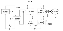
- FIG. 6 shows a configuration example of the solar steam cycle system of Comparative Example 1.
- This system is supplied from a heat collector 1 that collects solar thermal energy, a heat accumulator 2 that stores heat energy collected by the heat collector 1, a feed water heater 3 that heats feed water, and the feed water heater 3.
- An evaporator 4 that heats water to generate steam
- a steam turbine 6 that is driven by the steam generated in the evaporator 4, and a condenser that cools and condenses the steam discharged from the steam turbine 6 and returns it to water 7 as a basic component
- a heat medium holding the solar heat energy collected in the heat collector 1 is transported and stored in the heat accumulator 2 through the piping path 11, and the heat stored in the heat accumulator 2 is piped by another heat medium.
- the solar thermal energy is effectively used for the steam cycle including the steam turbine 6.
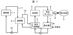
- FIG. 7 shows another configuration example of the solar thermal steam cycle system as Comparative Example 2.
- the basic components of the heat collector 1, the heat accumulator 2, the feed water heater 3, the evaporator 4, the steam turbine 6, and the condenser 7 are the same as those in FIG. 6 and stored in the heat accumulator 2.
- the heat medium is transported through the piping path 13 and supplied to the feed water heater 3.
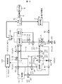
- FIG. 1 shows a first embodiment of the solar steam cycle system of the present invention. This system is similar to the above-described comparative example (FIGS. 6 and 7) in the heat collector 1, the heat accumulator 2, the feed water heater 3, the evaporator 4, the steam turbine 6, the condenser 7 and the heat accumulator 2.
- a piping path 12 for transporting the heat medium In order to use the stored heat for the evaporator 4, a piping path 12 for transporting the heat medium, and in order to use the heat stored in the heat storage 2 for the feed water heater 3, a piping path 13 for transporting with the heat medium is provided. Yes.
- a flow rate adjusting valve 31 that changes the distribution of the flow rate of the heat medium that flows through the piping path 12 from the regenerator 2 to the evaporator 4 and the piping path 13 from the regenerator 2 to the feed water heater 3.
- heat storage amount For measuring or estimating the heat storage amount and the information on the heat storage amount obtained by the heat storage amount acquisition unit 20 and when the heat storage amount is larger than a predetermined reference, the heat utilization pipe for the evaporator When the heat medium flow rate distribution to 12 is relatively increased and the heat storage amount is smaller than a predetermined reference, the heat medium flow rate distribution to the heat supply pipe 13 for the feed water heater is relatively increased.
- the flow control valve 31 and the valve 32 And a control device 100 which determines the degree of
- This system uses, for example, a criterion for determining the amount of heat stored in the heat accumulator 2 (that is, the amount of heat stored by the heat storage amount acquisition means 20, calculated, or estimated) as “the temperature of the heat storage medium is generated in the evaporator 4. If it is higher than the temperature required for the above, if this criterion is met, the heat utilization to the evaporator 4 will be relatively large, so the heat stored at a high temperature should be used effectively for the high temperature use. Can do. On the other hand, when this standard is not satisfied, for example, the operation can be performed such that the heat supply to the evaporator 4 is shut off and the valves 31 and 32 are switched so that the entire amount is used for the heat utilization to the feed water heater 3.
- the second criterion “whether the temperature of the heat storage medium is higher than the temperature necessary for heating the feed water with the feed water heater 3” is determined.
- the opening degree command value of the valve 32 is determined so as to supply heat to the heater 3, and if it is not satisfied, the calculation related to the utilization of heat to the feed water heater so as to generate a fully closed command for the valves 31 and 32 not to supply heat. It is also possible to construct a circuit. In this case, when the second criterion is not satisfied, the heat storage device 2 continues to store heat as it is, and the entire system without reducing efficiency on the steam cycle side including the feed water heater 3, the evaporator 4, and the steam turbine 6 is achieved.
- the heat storage amount in the heat storage amount acquisition means 20 is acquired by, for example, a temperature sensor (not shown in the figure) installed in the heat storage 2, and uses the temperature T of the heat storage body, the mass M of the heat storage body, and the specific heat Cp.
- Q (T ⁇ T0) ⁇ M ⁇ Cp (where temperature T0 indicates a reference temperature for calorie calculation).
- T0 indicates a reference temperature for calorie calculation
- the temperature T of the heat storage body substantially indicates the amount of heat stored, so it is also possible to indirectly indicate the heat storage amount by T-T0. .
- the heat storage amount acquisition means 20 receives the measured value of the heat storage body temperature of the heat storage device 2 or the estimated value of the related information in this way, and quantitatively calculates the degree of heat stored in the heat storage body as described above. What is necessary is just to provide an arithmetic circuit and to output the calculated heat storage amount.
- the above-mentioned criteria for determining the amount of heat stored in the heat accumulator 2 for example, “whether the temperature of the heat storage medium is higher than the temperature required for steam generation in the evaporator 4”, “the temperature of the heat storage medium is the feed water heater)
- the non-determined mechanical calculation method of “whether the temperature is higher than the temperature necessary for heating the feed water in 3” is the temperature to be heated (steam temperature in the case of the evaporator 4, and in the case of the feed water heater 3).
- the temperature calculated based on (M ⁇ Cp)) is used as an input, and the evaluation may be performed based on a comparison of the magnitudes.
- control device 100 described above is specifically realized as a control panel having an input / output terminal and an internal circuit, and the heat storage amount acquired by the heat storage amount acquisition means 20 is an input signal to the control panel.
- the mechanical calculation of whether or not the heat storage amount satisfies the above-described determination criterion of the heat storage amount, and the flow distribution value to the piping path 12 and the piping path 13 according to the determination result or the presence or absence of switching are implemented in the control panel. This is executed by a predetermined calculation formula in the internal arithmetic circuit, and finally becomes a signal output from the control panel as an opening degree command or an opening / closing command (including a switching command) to the flow rate adjusting valve 31 and the valve 32.
- the calculation formula predetermined by the internal arithmetic circuit is, for example, that the determination result is the above-mentioned determination criterion for the first heat storage amount “Is the temperature of the heat storage medium higher than the temperature required for steam generation in the evaporator 4?
- the determination result is the above-mentioned determination criterion for the first heat storage amount “Is the temperature of the heat storage medium higher than the temperature required for steam generation in the evaporator 4?
- the flow distribution of the heat medium to the heat utilization pipe 12 for the evaporator is relatively increased, and when not satisfying, the flow rate of the heat medium to the heat utilization pipe 13 for the feed water heater What is necessary is just to determine the opening degree of the valves 31 and 32 that relatively increase the distribution, or, for example, the above-mentioned second criterion “the temperature of the heat storage medium heats the feed water with the feed water heater 3.
- the valve 31, 32 is opened to supply heat to the feed water heater 3 when the determination criterion “whether the temperature is higher than the temperature required for the operation” is satisfied, and when it is not satisfied, the valves 31, 32 are fully closed so as not to supply heat. What determines the opening of the valves 31, 32 Good.
- the condenser 7 of the present system includes a cooling means for allowing heat exchange by flowing deep ocean water obtained from a pipe line from a depth of about 200 meters or more in order to condense the inflowing steam. Still good. In this case, the efficiency of the entire system can be further improved. This is because the temperature of deep ocean water is generally about 10 ° C or lower, which is lower than the temperature of seawater or the like normally used as cooling water, so the vacuum level of the condenser increases, which increases the heat drop of the steam turbine. In addition, the suction effect of steam discharged from the low pressure stage of the steam turbine to the condenser increases, and the efficiency and output of the steam turbine increase. When this system is configured in this way, energy that can be pumped up according to the location environment by utilizing the temperature difference between the hottest natural heat source called solar heat and the coldest natural heat source called deep ocean water in the surrounding environment. Can be efficiently obtained from the surrounding natural environment.
- this figure has been described by taking the condensing turbine system including the condenser 7 as an example, but it is also possible to configure the whole as a back pressure turbine system that does not include the condenser. is there.
- the difference from FIG. 1 is that the steam discharged from the steam turbine 6 without the condenser 7 is supplied or released for use such as heat utilization, and the water supply to the feed water heater 3 is recovered. It is not a circulation from the water vessel 7 but an independent water supply system.
- the specification of the steam turbine 6 may change from a condensing turbine to a back pressure turbine. However, it is still possible to efficiently use heat by switching the heat utilization destination between the evaporator and the feed water heater according to the heat storage state.
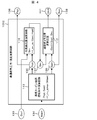
- FIG. 2 shows a second embodiment of the solar steam cycle system of the present invention.
- This system is similar to the above-described comparative example (FIGS. 6 and 7), and includes a heat collector 1, a heat accumulator 2, a feed water heater 3, an evaporator 4, a steam turbine 6, and a heat accumulator 1 to a heat accumulator. 2 is connected to the heat accumulator piping path 11 (in the figure, the path from the heat collector 1 through the valves 33 and 36 to the heat accumulator 2), and the heat stored in the heat accumulator 2 is used for the evaporator 4.
- the piping path 12 for transporting the heat medium (in the figure, the path from the heat accumulator 2 to the evaporator 4 via the valves 37, 38, 39, and 34), the heat stored in the heat accumulator 2 is used in the feed water heater 3. Therefore, it has a piping path 13 (in the figure, a path from the heat accumulator 2 through the valves 37, 38, 39 to the feed water heater 3) for transporting with a heat medium.
- a piping path 15 (a path from the heat collector 1 to the evaporator 4 via the valves 33 and 34 in the figure) for passing a heat medium from the heat collector 1 to the evaporator 4, and a heat collector
- a piping path 16 for passing a heat medium from 1 to the feed water heater 3 (in the figure, a path from the heat collector 1 through the valves 33, 36, 38, 39 to the feed water heater 3) and the heat collector 1 or heat storage
- a piping path 14 for recirculating the flow of the heat medium supplied from the cooler 2 while avoiding the feed water heater 3 (in the figure, from the heat collector 1 to the pump 81 via valves 33, 36, 38, 37, 40) Flow, or flow from the regenerator 2 through the valves 37 and 40 to the pump 81), and the pipe path 12 from the heat accumulator 2 to the evaporator 4 and the pipe path 13 to the feed water heater 3.
- a flow rate control valve 39 for changing the distribution of the flow rate of the heat medium, the evaporator 4 and the feed water heater A valve 35 that switches or merges the flow of the heat medium flowing back from the heat collector 1 to the heat collector 1, and a heat medium that flows through the pipe path 11 from the heat collector 1 to the heat accumulator 2 and the pipe path 15 to the evaporator
- a flow rate adjustment valve 33 that changes the distribution of the flow rate, and a valve 34 that switches or merges the piping path 15 from the heat collector 1 to the evaporator 4 and the piping path 12 from the heat accumulator 2 to the evaporator 4;
- the piping path 11 from the heat collector 1 to the heat accumulator 2 here, in particular, the path portion from the valve 36 to the heat accumulator 2 and the piping path 17 from the heat collector 1 to the feed water heater 3 (numbers omitted in the figure).
- the flow path after the valve 36), the flow rate adjusting valve 36 for changing the distribution of the flow rate of the heat medium to be passed, and the heat collector 1 The piping path 17 (particularly the valve 38) from the 39 to the feed water heater 3) and the piping path 14 (especially the flow from the valve 38 to 37 to 40 to the pump 81) to avoid heat supply from the heat collector 1 to the feed water heater 3.
- the flow rate control valve 38 that changes the distribution of the flow rate of the heat medium and the flow rate of the heat medium that is passed through the piping path 13 from the heat accumulator 2 to the feed water heater 3 or further the supply of heat to the feed water heater 3 is avoided.
- a flow rate adjusting valve 37 that changes the flow rate of the heat medium in the piping path 14 (here, in particular, the flow from the valves 37 to 40 to the pump 81), the regenerator 2 and the feed water heater 3 returns to the heat collector 1.
- a valve 40 that switches or merges the flow of the heat medium, a heat collection amount acquisition means 10 that measures or estimates the temperature or total heat amount (hereinafter referred to as heat collection amount) of the heat collected in the heat collector 1, and the heat accumulator 2 Stored heat temperature or total heat
- the heat storage amount acquisition means 20 which measures thru
- the control device 100 receives information on the heat collection amount obtained by the heat collection amount acquisition means 10 or information on the heat storage amount obtained by the heat storage amount acquisition means 20 (hereinafter referred to as collectable heat amount as appropriate), and i) the heat collection amount is determined in advance.
- collectable heat amount information on the heat collection amount obtained by the heat collection amount acquisition means 10 or information on the heat storage amount obtained by the heat storage amount acquisition means 20
- the flow rate adjustment valve 33 is opened so that the flow rate of the piping path 15 from the collector 1 to the evaporator 4 is larger than the piping path 16 from the collector 1 to the feed water heater 3.
- Degree command value (including full-closed full-open switching of the two paths) is determined, and ii) the flow rate of the piping path 15 from the heat collector 1 to the evaporator 4 when the heat collection amount is smaller than a predetermined reference Is determined to be smaller than the piping path 16 from the heat collector 1 to the feed water heater 3, and the opening command value of the flow rate adjustment valve 33 (including switching between the two paths) is determined.
- a predetermined reference determined to be smaller than the piping path 16 from the heat collector 1 to the feed water heater 3
- the opening command value of the flow rate adjustment valve 33 (including switching between the two paths) is determined.
- the flow rate of the piping path 12 from the heat storage device 2 to the evaporator 4 is higher than the flow rate of the piping route 13 from the heat storage device 2 to the feed water heater 3.
- the opening command value (including the switching of the two paths) of the flow rate adjusting valve 39 is determined so as to increase, and ii) when the heat storage amount is smaller than a predetermined reference, the heat storage device 2 to the evaporator 4
- the opening command value of the flow rate adjustment valve 39 (including switching between the two paths) is determined so that the flow rate of the pipe path 12 is smaller than the flow rate of the pipe path 13 from the regenerator 2 to the feed water heater 3.
- this system has a ratio of high-temperature usage and low-temperature usage at the heat usage destination according to the criterion for the amount of heat stored in the heat accumulator 2 (the temperature used in the evaporator 4 is Since it can change the utilization temperature in the feed water heater 3, the heat is more efficiently constituted by the steam cycle side (the feed water heater 3, the evaporator 4, and the steam turbine 6) according to the heat storage state. System).
- the configuration and effects in the case of using the second determination criterion described in the example of FIG. 1 are the same.
- the heat collected by the heat collector 1 by the combination of the valve 33 and the valve 36 is supplied to the evaporator 4 or the feed water heater 3 or the regenerator 2 and used.
- the distribution can be adjusted. That is, the distribution of heat utilization to the evaporator 4 can be adjusted by the valve 33, and the amount of the remaining heat that has not been distributed to the evaporator 4 by the valve 36 can be adjusted to the feed water heater 3 and the regenerator 2, respectively. . Therefore, for example, the criterion for the amount of heat collected by the heat collector 1 is “the temperature of the heat medium heated by the heat collector 1 and supplied toward the valve 33 is higher than the temperature required for steam generation in the evaporator 4.
- the heat utilization to the evaporator 4 is relatively increased, and the heat collected at a high temperature can be effectively used for the use of the high temperature
- the heat utilization to the feed water heater 3 is relatively increased or the entire amount is used for the heat utilization of the feed water heater 3 (the heat utilization to the evaporator 4 is cut off), thereby reducing the temperature.
- Even the heat collected in the above can be used as it is, and the remaining heat can be stored in the regenerator 2.
- the ratio of the high temperature and the low temperature at the heat utilization destination (the utilization temperature in the evaporator 4 is higher than the utilization temperature in the feed water heater 3. Therefore, the heat can be effectively used on the steam cycle side (system constituted by the feed water heater 3, the evaporator 4, and the steam turbine 6) more efficiently according to the heat collection state.
- the control device 101 supplies heat to the feed water heater 3 when this criterion is satisfied.
- calculation related to heat utilization to the feed water heater so as to determine the valve opening command value according to the flow rate distribution for the heat accumulator 2 and the feed water heater 3 in the valve 36 It is also possible to construct a circuit.
- the valve 33 is closed to the evaporator 4 and the valve 36 is closed. Is closed to the heat accumulator 2, the valve 38 is closed to the feed water heater 3, and the valve 37 is opened and closed (the opening degree is set to open the path for returning to the heat collector 1.
- An arithmetic circuit for generating a low amount of heat may be included in the control device 101. In this case, when the heat collection amount does not satisfy the second criterion, the low temperature heat collected by the heat collector bypasses all of the evaporator 4, the feed water heater 3, and the heat accumulator 2.
- the feed water and steam of the steam cycle system (system consisting of feed water heater 3, evaporator 4 and steam turbine 6) It is possible to operate by avoiding cooling to reduce efficiency.
- the heat collection amount acquisition means 10 receives the measured value or estimated value of the heat medium temperature flowing through the heat collector 1 in this way, and quantitatively determines the amount of heat collected in the heat collector as shown in the above equation. What is necessary is just to provide the arithmetic circuit which calculates and to output the calculated heat collecting amount.
- a criterion for determining the amount of heat collected in the above-described heat collector 1 (for example, “whether the temperature of the heat medium is higher than the temperature necessary for generating steam in the evaporator 4”, “the temperature of the heat medium is heated by feed water)
- the non-determining mechanical calculation method of “whether the temperature is higher than the temperature necessary for heating the feed water in the vessel 3” is the temperature to be heated (in the case of the evaporator 4, the steam temperature, the feed water heater 3
- the above relational expression (for example, q) is obtained from the water supply temperature or the target temperature of the water supply heating) and the temperature acquired by the heat collection amount acquisition means 10 (or the heat quantity or quality index acquired by the heat collection amount acquisition means 10).
- the measurement or calculation / estimation method of the heat storage amount in the heat storage amount acquisition means 20 and the criterion for determining the heat storage amount are the same as those in FIG.
- control device 101 described above is specifically realized as a control panel having an input / output terminal and an internal circuit, and is acquired by the heat collection amount acquired by the heat collection amount acquisition unit 10 or the heat storage amount acquisition unit 20. At least one of the heat storage amounts (hereinafter referred to as “usable heat amount”) is an input signal to the control panel, mechanical calculation of whether the available heat amount satisfies the above-mentioned determination criteria, and an evaporator according to the determination result 4.
- Opening command of each valve corresponding to the flow distribution value of the heat medium to the feed water heater 3 and the heat accumulator 2 Is executed by a predetermined calculation formula in an internal arithmetic circuit mounted in the control panel, and finally controlled as an opening degree command or an opening / closing command (including a switching command) to the valves 33, 36, 38, 37.
- the calculation formula determined in advance by the internal arithmetic circuit is the opening degree or opening / closing of each valve according to the determination result of the heat collection amount or the heat storage amount, as described for the control device 101 in the description of the system configuration.
- the above-mentioned second determination criterion determination criterion of whether or not the temperature of the heat storage medium is higher than the temperature necessary for heating the feed water in the feed water heater 3”
- the second determination criterion determines whether or not the temperature of the heat storage medium is higher than the temperature necessary for heating the feed water in the feed water heater 3
- FIG. 2 is different from the example of FIG. 1 described above in that it can cope with fluctuations with a shorter time scale. This is because the amount of heat collected by the heat collector 1 (that is, the amount of heat collected by the heat collection amount acquisition unit 10) is more time-consuming than the amount of heat stored by the heat storage unit 2 (the amount of heat stored by the heat storage amount acquisition unit 20).
- the valves 33, 36, 38, and 37 are provided, and the evaporator 4 and the feed water heater 3 and the heat storage are provided with heat according to the heat collection state (especially temperature or heat quantity). This is because the recovered heat amount that varies depending on the solar radiation condition can be used without loss as it is.
- the heat storage 2 is stopped due to maintenance or failure in this system in which the heat collected by the heat collector 1 is distributed and controlled to the evaporator 4, the feed water heater 3 and the heat storage 2 without going through the heat storage 2. It can be used even when the amount of heat exceeding the capacity of the heat accumulator 2 is collected by the heat collector 1, and is useful.
- the system that distributes and controls the heat collected by the heat collector 1 to the evaporator 4, the feed water heater 3, and the heat accumulator 2 without going through the heat accumulator 2 is the heat accumulator 2 due to the limitation of the site area.
- the system corresponding to such a case is effective for the heat storage device 2, the heat storage amount acquisition means 20, and the heat input to the heat storage device 2 from the components shown in FIG. It is possible to configure without the valves 36 and 37 for adjusting the output.
- the condenser 7 of the present system when deep ocean water or the like is used as cooling water for condensing steam, the efficiency of the entire system can be further improved. Can do.
- the condenser 7 can be removed from the system configuration, and the steam turbine 6 can be configured as a back pressure turbine instead of a condensing turbine. And flexible operability at the time of maintenance or failure of the heat accumulator or when the heat storage capacity is exceeded.
- FIG. 3, FIG. 4 and FIG. 5 show examples of control methods that operate with higher efficiency in consideration of the equipment characteristics of the steam cycle. These solve the problem of the solar thermal steam cycle system, that is, the problem that the steam pressure fluctuates due to the change in the amount of solar radiation, and the steam turbine efficiency cannot always be kept at the maximum. (Note that the steam pressure fluctuates depending on the amount of solar radiation.
- the temperature of the heat medium collected in the heat collector 1 or the heat accumulator 2 varies depending on the amount of solar radiation, and heat is exchanged between the heat medium and the evaporator 4. This is because the temperature of the steam cannot exceed the temperature of the heat medium, for example, if the temperature of the heat medium is low in a time zone where the amount of solar radiation is low, such as early morning or night, the steam temperature is also lower than during the day).
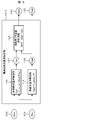
- the prerequisite system configuration is the same as that shown in FIG. 2, but the specific configuration according to this embodiment is as follows.
- the auxiliary boiler 5 that generates steam using a heat source or fuel different from the evaporator 4 and the pressure and flow rate of the evaporator 4 are measured or estimated, respectively.
- the pressure acquisition means 73 and the flow rate acquisition means 74 to be calculated and acquired, and the temperature acquisition means 71 to acquire the temperature and flow rate of the heat medium supplied from the heat collector 1 to the evaporator 4 by measuring or estimating / calculating, And a flow rate acquisition means 72.
- the control device 101 appropriately uses signals obtained by the pressure acquisition unit 73, the flow rate acquisition unit 74, the temperature acquisition unit 71, and the flow rate acquisition unit 72 as input information.
- FIGS. 3, 4 and 5 will be described below.
- FIG. 3 shows an example of an arithmetic circuit (optimal auxiliary steam flow rate arithmetic circuit 1011) provided in the control device 101 (FIG. 2).
- the optimum auxiliary steam flow rate calculation circuit 1011 includes the steam pressure 131 (FIG. 3) acquired by the pressure acquisition unit 73 (FIG. 2) and the evaporator flow rate 132 (FIG. 2) acquired by the flow rate acquisition unit 74 (FIG. 2). 3) The steam turbine optimum steam flow 135 (FIG. 3) and the auxiliary boiler optimum flow for maintaining high efficiency of the steam turbine 6 (FIG. 2) by receiving (the feed water flow rate or the evaporation flow rate to the evaporator 4) as an input.
- 141 FIG. 3
- the optimum auxiliary steam flow rate calculation circuit 1011 receives the input of the steam pressure 131 and sets the steam flow rate 135 at which the efficiency of the steam turbine 6 (FIG. 2) is maximized based on a predetermined relationship.
- An optimum flow rate calculation circuit 111 that calculates and outputs, an input of the optimum steam turbine flow rate 135 output from the optimum flow rate calculation circuit 111 and the evaporator flow rate 132, and the subtracting the latter from the former is the auxiliary boiler flow rate 141, an auxiliary boiler flow rate calculation circuit 112 that calculates and outputs the flow rate as 141 (the flow rate is zero in the case of a negative value) is provided.
- the optimum flow rate calculation circuit 111 is configured so that the steam flow rate at which the turbine efficiency is maximized is output when the steam pressure is input. It is functionalized in the form of a correlation equation.
- the overall system operation control mechanism using the optimum auxiliary steam flow rate calculation circuit 1011 will be described with reference to FIG.
- the optimum auxiliary steam flow rate calculation circuit 1011 (FIG. 3) is incorporated in the control device 101 (FIG. 2).
- the auxiliary boiler optimum flow rate 141 and steam output from the optimum auxiliary steam flow rate calculation circuit 1011 are stored.
- a turbine optimum flow rate 135 is obtained.
- the acquired optimum flow rate 141 of the auxiliary boiler is opened to the flow rate adjustment valve 41 that distributes the feed water flow rate to the evaporator 4 and the auxiliary boiler 5 (from the feed water heater 3) so that the flow rate of the auxiliary boiler 5 matches this. Converted to degree command value.
- the acquired optimum steam turbine flow rate 135 is converted into a feed water command value for the pump 83 that feeds the entire steam cycle (system comprising the feed water heater 3, the evaporator 4, the auxiliary boiler 5, and the steam turbine 6).
- the opening command value thus obtained is transmitted as a signal to the flow rate adjustment valve 41 and the water supply command value is transmitted as a signal to the water supply pump 83, and the flow rate adjustment valve 41 and the water supply pump 83 operate in response thereto, whereby the entire system is operated. Be controlled.
- This system calculates the optimum steam flow rate in terms of steam turbine efficiency with respect to the fluctuating steam pressure by the optimum flow rate calculation circuit 111, and the steam generated by the steam turbine 6 (or the evaporator 4 and the auxiliary boiler 5) is guided.
- the steam turbine 6 can be operated with high efficiency.
- the system is suitable for optimal operation of the system based on the pressure and flow rate of steam generated in the solar thermal system.
- the power generation output of the steam turbine 6 is determined depending on the steam pressure 131 and the flow rate 135, when the operation according to the command value of the power generation output is not required, that is, the power system 9 (FIG. 2)
- the plant There is a power supply facility other than the plant of this system (hereinafter referred to as “the plant”), and in this plant, it is sufficient to generate only the amount that can be recovered from solar heat for the required power demand. Is preferred.
- the water supply system to the auxiliary boiler is branched from the system from the feed water heater 3 to the evaporator 4, but the water supply system to the auxiliary boiler 5 is configured separately from the water supply to the evaporator. May be.
- the auxiliary boiler feed water flow rate control system in this case is configured to operate the feed water pump flow rate to the auxiliary boiler 5 so as to be the optimum auxiliary boiler flow rate 141 (the value calculated by the optimum auxiliary steam flow rate calculation circuit 1011). Just do it. The same applies to the following examples (FIGS. 4 and 5).
- the optimum auxiliary steam flow rate calculation circuit 1011 is configured by a plurality of calculation circuits (optimal flow rate calculation circuit 111 and auxiliary boiler flow rate calculation circuit 112). It is not intended to indicate that the operation chip is configured, but only to explain the functional configuration, and any actual control circuit may have a function corresponding to these circuits (hereinafter referred to as “the control circuit”). The same applies to the examples).
- FIG. 4 shows another example (optimum steam pressure / flow rate calculation circuit 1012) of the calculation circuit provided in the control device 101 (FIG. 2).
- the optimum steam pressure / flow rate calculation circuit 1012 has a value of the available heat amount 133 (FIG. 4) that is collected in the heat collector 1 (FIG. 2) or stored in the heat accumulator 2 (FIG. 2), and
- the power demand 134 (FIG. 4) of the power system 9 (FIG. 2) to which the power generated by the generator 8 (FIG. 2) of the steam turbine 6 (FIG. 2) is supplied is received as an input, and the steam turbine 6 ( Steam turbine optimum pressure 136 (FIG. 4), steam turbine optimum flow rate 138 (FIG.
- the available heat amount 133 is specifically the heat amount acquired by the heat collection amount acquisition means 10 (FIG. 2) or the heat storage amount acquisition means 20 (FIG. 2), or the temperature acquired by the temperature acquisition means 71.
- the value of the power demand 134 is obtained separately by any known method such as time series prediction or a neural network.
- the optimum steam pressure / flow rate calculation circuit 1012 receives the input of the electric power demand 134 and receives the input of the electric power demand 134 to obtain the electric power generation amount corresponding to the electric power demand. That is, the steam turbine optimum operating condition calculation circuit 113 that specifies and outputs a combination of the optimum steam pressure 136 and the optimum steam flow rate 138 that gives the highest steam turbine efficiency, and the steam turbine optimum operating condition calculation circuit 113 output the result.
- the optimum steam pressure 136 and the above-mentioned available heat quantity 133 are received as inputs, and the steam flow 137 (hereinafter referred to as the available steam flow) obtained when the available heat quantity 133 is converted into steam having the steam pressure 136 by the evaporator 4.
- a boiler flow rate calculation circuit 112 is provided.
- the overall system operation control mechanism using the optimum steam pressure / flow rate calculation circuit 1012 (optimum steam pressure / flow rate calculation circuit) will be described with reference to FIG.
- the optimum steam pressure / flow rate calculation circuit 1012 (FIG. 4) is incorporated in the control device 101 (FIG. 2).
- the optimum steam turbine flow rate 138 and the optimum auxiliary boiler flow rate 141 are acquired.
- the acquired steam turbine optimum pressure 136 is equal to the pressure of the steam cycle (system consisting of feed water heater 3, evaporator 4, auxiliary boiler 5, steam turbine 6) measured by the pressure acquiring means 73.
- the acquired optimum auxiliary boiler flow rate 141 is a flow rate adjustment valve 41 that distributes the feed water flow rate to the evaporator 4 and the auxiliary boiler 5 (from the feed water heater 3) so that the flow rate of the auxiliary boiler 5 matches this. Is converted into an opening command value. This is executed in the control device 101 using a predetermined flow rate-opening relationship of the valve 41.
- the acquired optimum steam turbine flow rate 138 is converted into a feed water command value for the pump 83 that feeds the entire steam cycle (system comprising the feed water heater 3, the evaporator 4, the auxiliary boiler 5, and the steam turbine 6). .
- the obtained optimum steam pressure value is transmitted as a signal to the pressure adjustment valve 43 of the steam cycle, the opening degree command value is transmitted to the flow rate adjustment valve 41, and the feed water command value is transmitted to the feed water pump 83 as a signal.
- the flow rate adjusting valve 41 and the water supply pump 83 are operated in response to this, whereby the entire system is controlled.
- the steam pressure 136 and the flow rate 138 at which the steam turbine efficiency is maximized in response to fluctuations in power demand are calculated by the steam turbine optimum operating condition calculation circuit 113, and the pressure of the steam cycle is set so that this condition is satisfied.
- the flow rate of the auxiliary boiler 5 is determined by subtracting the estimated value 137 of the amount of steam that can be recovered from the solar thermal system from the optimal flow rate 138 so that the steam flow rate supplied to the steam turbine 6 matches this optimal flow rate 138. (Auxiliary boiler flow rate calculation circuit 112) allows the steam turbine 6 to be operated with high efficiency.
- this system is suitable for optimal system operation when it is possible to obtain information on both the amount of heat recoverable in the solar thermal system and the power demand on the power system side.
- it is suitable for a case where a command value of power generation output is received from the power system side and operation is performed in conjunction with the system, or when a so-called island operation in which the power system 9 is separated from the outside of the target area and exists independently is required. It is.
- FIG. 5 shows another example (optimum steam flow rate calculation circuit 1013) of the calculation circuit provided in the control device 101.
- the optimum steam flow rate calculation circuit 1013 includes the value of the available heat amount 133 (FIG. 5) that is collected in the heat collector 1 (FIG. 2) or stored in the heat accumulator 2 (FIG. 2) and the pressure. With the steam pressure 131 (FIG. 5) acquired by the acquiring means 73 (FIG. 2) as an input, the optimum steam flow rate 135 (FIG. 5) and auxiliary boiler for maintaining the efficiency of the steam turbine 6 (FIG. 2) high.
- the optimum flow rate 141 (FIG. 5) (the feed water flow rate or the evaporation flow rate of the auxiliary boiler 5) is output.
- the optimum steam flow rate calculation circuit 1013 receives therein the available heat quantity 133 and the steam pressure 131 as input, and the steam obtained when the available heat quantity 133 is converted into steam at the steam pressure 131 by the evaporator 4.
- An evaporator flow rate calculation circuit 114 that estimates and outputs a flow rate 137 (hereinafter referred to as an available steam flow rate) and the steam pressure 131 are received, and the efficiency of the steam turbine 6 (FIG. 2) is maximized at that pressure.
- the optimum flow rate calculation circuit 111 that calculates and outputs a specific steam flow rate 135 based on a predetermined relationship, the optimum steam turbine flow rate 135 output from the optimum flow rate calculation circuit 111, and the use generated in the evaporator 4 described above Receives the input of the flow rate 137 of the possible steam and outputs the auxiliary boiler flow rate 141 obtained by subtracting the latter from the former.
- To comprises an auxiliary boiler flow rate computation circuit 112.
- the contents of the evaporator flow rate calculation circuit 114 are as shown in FIG. 4, the optimum flow rate calculation circuit 111 is the same as that shown in FIG. 3, and the auxiliary boiler flow rate calculation circuit 112 is the same as the calculation circuit shown in FIGS. It is the same.
- the overall system operation control mechanism using the optimum steam flow rate calculation circuit 1013 will be described with reference to FIG.
- the optimum steam flow rate calculation circuit 1013 (FIG. 5) is incorporated in the control device 101 (FIG. 2), and in the control device 101, the auxiliary boiler optimum flow rate 141 output from the optimum steam flow rate calculation circuit 1013 and the steam turbine optimum.
- a flow rate 135 is acquired.
- the mechanism in which the overall system (FIG. 2) is operated and controlled based on the acquired auxiliary boiler optimum flow rate 141 and the steam turbine optimum flow rate 135 is the same as in the case of FIG. 3.
- the optimum steam flow rate 135 at which the turbine efficiency of the steam turbine 6 is maximized with respect to the steam pressure 131 that fluctuates depending on the solar heat radiation conditions is calculated by the optimum flow rate calculation circuit 111, and the steam flow rate supplied to the steam turbine 6 is calculated.
- the flow rate 141 of the auxiliary boiler 5 is determined by subtracting the recoverable steam amount 137 of the solar thermal system from the optimal flow rate 135 so as to match the optimal flow rate 135 (auxiliary boiler flow rate calculation circuit 112), thereby improving the efficiency of the steam turbine 6. You can drive high.
- This system determines the steam turbine pressure statically or dynamically according to some criteria in advance (without depending on the heat recovery conditions of the solar thermal system), and then considers the amount of heat that can be recovered in the solar thermal system. Is suitable for the case of optimal operation, for example, when it is operated at a constant pressure.
- this system does not require the plant to operate according to the command value of the power generation output, and generates power by the amount recoverable from solar heat for the power demand necessary for the system 9. It is suitable for such a case.
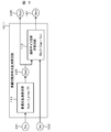
- FIG. 8 does not include the heat accumulator 2 but supplies the heat collected by the heat collector 1 to the evaporator 4 or the feed water heater 3 as it is with respect to the system of the first embodiment (FIG. 1) described above. Indicates the system to perform.
- the difference in operation control is that the determination of distribution / switching of the heat supply to the evaporator 4 and the feed water heater 3 in the control device 100 is based on the information of the heat storage amount stored in the heat accumulator 2 in the first embodiment (FIG. 1). In contrast, this is based on information on the amount of heat collected in the heat collector 1.
- the information on the amount of heat collected is the amount of heat obtained by the heat collection amount acquisition means 10 for measuring or estimating the temperature or total heat amount (hereinafter referred to as heat storage amount) of the heat collected in the heat collector 1, or the heat collector. 1 is obtained by a temperature acquisition means 71 and a flow rate acquisition means 72 that acquire and measure and estimate / calculate the temperature and flow rate of the heat medium supplied from 1 to the heat utilization side (evaporator 4 or feed water heater 3), respectively. It is acquired as the amount of heat calculated by a predetermined method based on the obtained value.
- the second embodiment (FIG. 2) is based on the heat collection amount acquisition means 10
- the fourth and fifth embodiments FIGS.
- the heat storage amount signal is merely a signal relating to the heat collection amount in this example, and the processing content based on the obtained heat amount is the same as in the case of the first embodiment (FIG. 1). It is.
- This system is effective when a simple system configuration is required because the heat utilization destination can be switched between the evaporator 4 and the feed water heater 3 in accordance with fluctuations in the amount of heat collected without the heat accumulator 2.
- a large heat storage capacity for absorbing fluctuations in supply and demand balance is not required, such as location conditions with relatively small fluctuations in the amount of collected heat and when the deviation in daily fluctuation patterns between the amount of collected heat and the amount of power demand is relatively small. It is suitable for the case where the heat accumulator 2 is difficult to install due to the restriction of the site area or the like.
- the present invention can be used as a solar thermal power generation system.
Landscapes
- Engineering & Computer Science (AREA)
- Chemical & Material Sciences (AREA)
- Combustion & Propulsion (AREA)
- Mechanical Engineering (AREA)
- General Engineering & Computer Science (AREA)
- Life Sciences & Earth Sciences (AREA)
- Sustainable Development (AREA)
- Sustainable Energy (AREA)
- Physics & Mathematics (AREA)
- Thermal Sciences (AREA)
- Engine Equipment That Uses Special Cycles (AREA)
Abstract
L'objectif de la présente invention consiste à produire un système de cycle de vapeur à chaleur solaire pouvant fonctionner de façon efficace et stable conformément à l'état de chaleur collectée ou de chaleur accumulée, et à produire un procédé de commande s'y rapportant.
Ce système de cycle de vapeur à chaleur solaire est équipé d'un collecteur de chaleur (1) qui collecte l'énergie thermique solaire, d'un accumulateur de chaleur (2) qui stocke l'énergie thermique solaire collectée à l'aide du collecteur de chaleur, d'un organe de chauffage pour alimentation en eau (3) qui chauffe l'eau apportée, d'un évaporateur (4) qui entraîne l'évaporation de l'eau apportée depuis l'organe de chauffage pour alimentation en eau et d'une turbine à vapeur (6) entraînée par la vapeur produite par l'évaporateur, et est caractérisé en ce qu'il est équipé d'une soupape de réglage (31) qui règle l'affectation de l'agent chauffant apporté à l'évaporateur et à l'organe de chauffage pour alimentation en eau depuis l'accumulateur de chaleur.
Priority Applications (4)
| Application Number | Priority Date | Filing Date | Title |
|---|---|---|---|
| JP2013503221A JP5537730B2 (ja) | 2011-03-07 | 2011-03-07 | 太陽熱蒸気サイクルシステム |
| US14/002,145 US9683557B2 (en) | 2011-03-07 | 2011-03-07 | Solar heat steam cycle system |
| EP11860400.8A EP2685101B1 (fr) | 2011-03-07 | 2011-03-07 | Système de cycle de vapeur à chaleur solaire |
| PCT/JP2011/001305 WO2012120556A1 (fr) | 2011-03-07 | 2011-03-07 | Système de cycle de vapeur à chaleur solaire |
Applications Claiming Priority (1)
| Application Number | Priority Date | Filing Date | Title |
|---|---|---|---|
| PCT/JP2011/001305 WO2012120556A1 (fr) | 2011-03-07 | 2011-03-07 | Système de cycle de vapeur à chaleur solaire |
Publications (1)
| Publication Number | Publication Date |
|---|---|
| WO2012120556A1 true WO2012120556A1 (fr) | 2012-09-13 |
Family
ID=46797573
Family Applications (1)
| Application Number | Title | Priority Date | Filing Date |
|---|---|---|---|
| PCT/JP2011/001305 Ceased WO2012120556A1 (fr) | 2011-03-07 | 2011-03-07 | Système de cycle de vapeur à chaleur solaire |
Country Status (4)
| Country | Link |
|---|---|
| US (1) | US9683557B2 (fr) |
| EP (1) | EP2685101B1 (fr) |
| JP (1) | JP5537730B2 (fr) |
| WO (1) | WO2012120556A1 (fr) |
Cited By (6)
| Publication number | Priority date | Publication date | Assignee | Title |
|---|---|---|---|---|
| WO2014076849A1 (fr) * | 2012-11-15 | 2014-05-22 | 三井造船株式会社 | Dispositif de production d'énergie électrique à stockage thermique et procédé pour commander ledit dispositif |
| WO2015114716A1 (fr) * | 2014-01-30 | 2015-08-06 | パナソニックIpマネジメント株式会社 | Système de transport de chaleur |
| WO2015156402A1 (fr) * | 2014-04-11 | 2015-10-15 | イビデン株式会社 | Système de stockage de chaleur solaire |
| KR101821333B1 (ko) * | 2014-04-11 | 2018-03-08 | 우한 카이디 엔지니어링 테크놀로지 리서치 인스티튜트 코오퍼레이션 엘티디. | 최적화되고 통합된 태양-바이오매스 하이브리드 발전 시스템 |
| WO2022209003A1 (fr) * | 2021-04-01 | 2022-10-06 | 株式会社 東芝 | Centrale de production d'énergie à accumulation de chaleur |
| JP2023008563A (ja) * | 2021-07-06 | 2023-01-19 | ヤンマーホールディングス株式会社 | 廃熱発電システム |
Families Citing this family (10)
| Publication number | Priority date | Publication date | Assignee | Title |
|---|---|---|---|---|
| BE1021499B1 (fr) * | 2012-12-21 | 2015-12-03 | Rutten - New Energy System S.A. | Centrale electrique thermique classique ou solaire thermodynamique a concentration |
| DK3259456T3 (en) * | 2015-03-20 | 2019-03-11 | Siemens Ag | HEATING OF HRSG IN REST |
| PL3269948T3 (pl) * | 2016-07-15 | 2022-07-18 | Carbon-Clean Technologies Gmbh | Sposób dostosowania mocy elektrowni z turbiną parową i elektrownia z turbiną parową |
| CN106968901A (zh) * | 2017-03-21 | 2017-07-21 | 江苏大学 | 一种气轮机式太阳能发电装置及其方法 |
| CA3173945C (fr) * | 2018-03-20 | 2025-03-11 | Steffes, Llc | Gestion d'énergie fondée sur le flux |
| EP3730749A1 (fr) * | 2019-04-24 | 2020-10-28 | Siemens Gamesa Renewable Energy GmbH & Co. KG | Procédé de charge efficace d'un système de conversion d'énergie |
| EP3933175A1 (fr) * | 2020-07-01 | 2022-01-05 | Siemens Gamesa Renewable Energy GmbH & Co. KG | Système de stockage d'énergie thermique |
| CN115704557B (zh) * | 2021-08-11 | 2025-12-12 | 中国石油化工股份有限公司 | 一种辅助稠油热采的太阳能蒸汽生产系统 |
| CN113700622B (zh) * | 2021-08-26 | 2022-08-05 | 西安交通大学 | 配置蒸汽储热罐的光热电站旁路蒸汽回收系统及运行方法 |
| CN117029286B (zh) * | 2023-07-17 | 2024-05-24 | 深圳市深汕特别合作区华润电力有限公司 | 锅炉换热装置 |
Citations (7)
| Publication number | Priority date | Publication date | Assignee | Title |
|---|---|---|---|---|
| JPS57150757A (en) * | 1981-03-13 | 1982-09-17 | Agency Of Ind Science & Technol | Solar heat utilizing plant |
| JPS59180016A (ja) | 1983-03-28 | 1984-10-12 | Hitachi Zosen Corp | 熱エネルギ−回収方法 |
| JPS6296704A (ja) * | 1985-10-23 | 1987-05-06 | Toshiba Corp | 温水利用タ−ビンプラント |
| JPH05272306A (ja) * | 1992-03-24 | 1993-10-19 | Toshiba Corp | 排熱利用発電制御装置 |
| DE4243401A1 (de) * | 1992-12-21 | 1994-06-30 | Axel Berger | Verfahren zur Umwandlung thermischer Energie in Elektroenergie |
| JP2007132330A (ja) | 2005-11-10 | 2007-05-31 | Kokusai Gijutsu Kaihatsu Co Ltd | 太陽熱発電装置 |
| JP2010190460A (ja) * | 2009-02-17 | 2010-09-02 | Hitachi Plant Technologies Ltd | 空調システム |
Family Cites Families (5)
| Publication number | Priority date | Publication date | Assignee | Title |
|---|---|---|---|---|
| JP2877098B2 (ja) | 1995-12-28 | 1999-03-31 | 株式会社日立製作所 | ガスタービン,コンバインドサイクルプラント及び圧縮機 |
| JP4322902B2 (ja) | 2006-08-10 | 2009-09-02 | 川崎重工業株式会社 | 太陽熱発電設備および熱媒体供給設備 |
| JP4786504B2 (ja) * | 2006-11-10 | 2011-10-05 | 川崎重工業株式会社 | 熱媒体供給設備および太陽熱複合発電設備ならびにこれらの制御方法 |
| WO2009062103A1 (fr) * | 2007-11-09 | 2009-05-14 | Markron Technologies, Llc | Hybridation héliothermique d'un cycle de rankine à combustible fossile |
| US8327641B2 (en) * | 2009-12-01 | 2012-12-11 | General Electric Company | System for generation of power using solar energy |
-
2011
- 2011-03-07 WO PCT/JP2011/001305 patent/WO2012120556A1/fr not_active Ceased
- 2011-03-07 EP EP11860400.8A patent/EP2685101B1/fr active Active
- 2011-03-07 JP JP2013503221A patent/JP5537730B2/ja active Active
- 2011-03-07 US US14/002,145 patent/US9683557B2/en active Active
Patent Citations (7)
| Publication number | Priority date | Publication date | Assignee | Title |
|---|---|---|---|---|
| JPS57150757A (en) * | 1981-03-13 | 1982-09-17 | Agency Of Ind Science & Technol | Solar heat utilizing plant |
| JPS59180016A (ja) | 1983-03-28 | 1984-10-12 | Hitachi Zosen Corp | 熱エネルギ−回収方法 |
| JPS6296704A (ja) * | 1985-10-23 | 1987-05-06 | Toshiba Corp | 温水利用タ−ビンプラント |
| JPH05272306A (ja) * | 1992-03-24 | 1993-10-19 | Toshiba Corp | 排熱利用発電制御装置 |
| DE4243401A1 (de) * | 1992-12-21 | 1994-06-30 | Axel Berger | Verfahren zur Umwandlung thermischer Energie in Elektroenergie |
| JP2007132330A (ja) | 2005-11-10 | 2007-05-31 | Kokusai Gijutsu Kaihatsu Co Ltd | 太陽熱発電装置 |
| JP2010190460A (ja) * | 2009-02-17 | 2010-09-02 | Hitachi Plant Technologies Ltd | 空調システム |
Non-Patent Citations (1)
| Title |
|---|
| See also references of EP2685101A4 |
Cited By (11)
| Publication number | Priority date | Publication date | Assignee | Title |
|---|---|---|---|---|
| WO2014076849A1 (fr) * | 2012-11-15 | 2014-05-22 | 三井造船株式会社 | Dispositif de production d'énergie électrique à stockage thermique et procédé pour commander ledit dispositif |
| JP2014098366A (ja) * | 2012-11-15 | 2014-05-29 | Mitsui Eng & Shipbuild Co Ltd | 蓄熱発電装置及びその制御方法 |
| WO2015114716A1 (fr) * | 2014-01-30 | 2015-08-06 | パナソニックIpマネジメント株式会社 | Système de transport de chaleur |
| WO2015156402A1 (fr) * | 2014-04-11 | 2015-10-15 | イビデン株式会社 | Système de stockage de chaleur solaire |
| KR101821333B1 (ko) * | 2014-04-11 | 2018-03-08 | 우한 카이디 엔지니어링 테크놀로지 리서치 인스티튜트 코오퍼레이션 엘티디. | 최적화되고 통합된 태양-바이오매스 하이브리드 발전 시스템 |
| WO2022209003A1 (fr) * | 2021-04-01 | 2022-10-06 | 株式会社 東芝 | Centrale de production d'énergie à accumulation de chaleur |
| JP2022158322A (ja) * | 2021-04-01 | 2022-10-17 | 株式会社東芝 | 蓄熱発電プラント |
| US12152510B2 (en) | 2021-04-01 | 2024-11-26 | Kabushiki Kaisha Toshiba | Thermal energy storage power plant |
| JP7814846B2 (ja) | 2021-04-01 | 2026-02-17 | 株式会社東芝 | 蓄熱発電プラント |
| JP2023008563A (ja) * | 2021-07-06 | 2023-01-19 | ヤンマーホールディングス株式会社 | 廃熱発電システム |
| JP7663435B2 (ja) | 2021-07-06 | 2025-04-16 | ヤンマーホールディングス株式会社 | 廃熱発電システム |
Also Published As
| Publication number | Publication date |
|---|---|
| EP2685101A1 (fr) | 2014-01-15 |
| US20140020383A1 (en) | 2014-01-23 |
| EP2685101A4 (fr) | 2014-12-24 |
| EP2685101B1 (fr) | 2015-09-16 |
| JPWO2012120556A1 (ja) | 2014-07-07 |
| JP5537730B2 (ja) | 2014-07-02 |
| US9683557B2 (en) | 2017-06-20 |
Similar Documents
| Publication | Publication Date | Title |
|---|---|---|
| JP5537730B2 (ja) | 太陽熱蒸気サイクルシステム | |
| EP3112679B1 (fr) | Système de génération et procédé de production d'énergie thermique solaire | |
| RU2508453C2 (ru) | Система аккумулирования термоэлектрической энергии с промежуточным баком-накопителем и способ аккумулирования термоэлектрической энергии | |
| US9476325B2 (en) | Method and apparatus of producing and utilizing thermal energy in a combined heat and power plant | |
| US8171733B2 (en) | Systems and methods involving combined cycle plants | |
| AU2015258171B2 (en) | Solar thermal power generation system | |
| CN104074692A (zh) | 利用太阳能的发电厂和海水淡化厂的统合系统 | |
| JP4875546B2 (ja) | 排熱発電装置、排熱発電装置の作動媒体蒸気過熱度制御方法 | |
| US20210167724A1 (en) | System and method for solar panel heat energy recovery, heat energy storage and generation from the stored heat energy | |
| CN103670554B (zh) | 发电供热装置 | |
| KR20130010470A (ko) | 배열 발전 방법 및 배열 발전 시스템 | |
| KR20190062802A (ko) | 해수온도차발전 시운전 및 잉여전력 활용을 위한 해수담수화 겸용 로드 뱅크 시스템 및 이의 제어방법 | |
| JP6188629B2 (ja) | バイナリー発電装置の運転方法 | |
| US20120324924A1 (en) | Thermal power upgrade facility | |
| JP4986664B2 (ja) | ガスタービン燃焼用空気の冷却システム | |
| JP5723220B2 (ja) | 発電プラント | |
| JPH1136818A (ja) | 排熱利用複合発電プラントの制御装置 | |
| WO2015060169A1 (fr) | Usine de production d'énergie | |
| WO2018173519A1 (fr) | Système de génération d'énergie de batterie | |
| KR102013829B1 (ko) | 증기사이클 기반의 폐열발전 열기관 및 이 열기관의 동작 방법 | |
| JP2017198142A (ja) | バイナリ発電システムおよびバイナリ発電方法 | |
| JP2007263519A (ja) | 排熱利用の吸収式冷温水機を用いた冷房システム | |
| Khaldi et al. | A Modified Solar/Gas Thermodynamic Hybridization Scheme in ISCC Plants for Reducing the Air-Cooled Condenser Power Consumption | |
| MA et al. | Experimental Investigation Regarding the Impact of Photovoltaic/Thermal (Pv/T) Control Parameters on the Performance of an Indirect Expansion Pv/T Assisted Heat Pump | |
| JP2019011937A (ja) | 熱エネルギー回収装置 |
Legal Events
| Date | Code | Title | Description |
|---|---|---|---|
| WWE | Wipo information: entry into national phase |
Ref document number: 2013503221 Country of ref document: JP |
|
| 121 | Ep: the epo has been informed by wipo that ep was designated in this application |
Ref document number: 11860400 Country of ref document: EP Kind code of ref document: A1 |
|
| WWE | Wipo information: entry into national phase |
Ref document number: 2011860400 Country of ref document: EP |
|
| NENP | Non-entry into the national phase |
Ref country code: DE |
|
| WWE | Wipo information: entry into national phase |
Ref document number: 14002145 Country of ref document: US |