WO2012120646A1 - Procédé de fabrication de moteur - Google Patents
Procédé de fabrication de moteur Download PDFInfo
- Publication number
- WO2012120646A1 WO2012120646A1 PCT/JP2011/055394 JP2011055394W WO2012120646A1 WO 2012120646 A1 WO2012120646 A1 WO 2012120646A1 JP 2011055394 W JP2011055394 W JP 2011055394W WO 2012120646 A1 WO2012120646 A1 WO 2012120646A1
- Authority
- WO
- WIPO (PCT)
- Prior art keywords
- coil
- jig
- taper
- shaped jig
- coils
- Prior art date
- Legal status (The legal status is an assumption and is not a legal conclusion. Google has not performed a legal analysis and makes no representation as to the accuracy of the status listed.)
- Ceased
Links
Images





Classifications
-
- H—ELECTRICITY
- H02—GENERATION; CONVERSION OR DISTRIBUTION OF ELECTRIC POWER
- H02K—DYNAMO-ELECTRIC MACHINES
- H02K15/00—Processes or apparatus specially adapted for manufacturing, assembling, maintaining or repairing of dynamo-electric machines
- H02K15/04—Processes or apparatus specially adapted for manufacturing, assembling, maintaining or repairing of dynamo-electric machines of windings prior to their mounting into the machines
- H02K15/0414—Processes or apparatus specially adapted for manufacturing, assembling, maintaining or repairing of dynamo-electric machines of windings prior to their mounting into the machines the windings consisting of separate elements, e.g. bars, segments or half coils
- H02K15/0421—Processes or apparatus specially adapted for manufacturing, assembling, maintaining or repairing of dynamo-electric machines of windings prior to their mounting into the machines the windings consisting of separate elements, e.g. bars, segments or half coils and consisting of single conductors, e.g. hairpins
- H02K15/0428—Processes or apparatus for simultaneously twisting two or more hairpins
Definitions
- the present invention relates to a motor manufacturing technique, and more specifically to a technique in which coils used in a stator are arranged in an annular shape and assembled to a stator core.
- a coil using a flat conductor becomes difficult to be deformed by increasing the cross-sectional area, and it is difficult to apply the assembly method that has been adopted for the conventionally used round wire coil. Even when a round wire coil is used, attention has been paid to the damage and disconnection of the coil. However, when a coil using a flat conductor is assembled to a motor, another difficulty arises.
- Patent Document 1 discloses a technique related to a stator coil insertion device.
- the stator core is inserted and held up to a predetermined position of a plurality of blades arranged at predetermined intervals on the same circumference.
- a plurality of blades are provided with coils at predetermined positions.
- the core guide that contacts the upper end of the fixed blade and the upper alignment also move upward as the fixed blade supported by the first stage movable part among the plurality of blades rises. Slide.
- the second stage movable part is raised to a predetermined position, the movable blade supported by the second stage movable part among the plurality of blades rises, and the aligned coils can be inserted into the slots of the stator core.
- Patent Document 2 discloses a technique related to an alignment method and alignment apparatus for segment conductors.
- a plurality of segment conductors including a pair of parallel insertion portions and a roof-type turn portion that joins one ends of both insertion portions are inserted into predetermined positions from predetermined slots of the stator core from one insertion portion and the other insertion portion, respectively. This is a method of aligning them.
- a positioning step of arranging a plurality of segment conductors in a radial pattern in a plan view, and moving one insertion portion of each segment conductor in a direction substantially perpendicular to the radiation direction in a plan view, more radiation direction than one insertion portion An alignment step of swinging the other insertion portion located on the outside around the one insertion portion and moving the insertion portion radially inward.
- Patent Document 3 discloses a technique related to a method for manufacturing a stator coil.
- the turn part of the built-in body is turned into a winding radius with respect to the core member in the course of feeding the built-in body into the core member.
- It is a built-in body in which the turn part is bent and formed into a staircase shape by plastic deformation into a bend R shape having substantially the same bend R radius, and the alignment accuracy and pitch accuracy in the layer part are improved. This technique improves the alignment accuracy in the staircase.
- Patent Document 4 discloses a technique related to an annular alignment jig and an annular alignment method for coil segments.
- the applicant has proposed a motor using a rectangular conductor coil with improved assemblability in an invention that has been separately filed.
- This rectangular conductor coil is a type in which a plurality of concentric winding coils are stacked and connected, and when the coil is assembled, one end of the coil protruding from the stator coil end is bent to the inner peripheral side of the stator. As a result, the assembly of the stator is improved.
- the coil having the shape of the present invention it seems that it is not appropriate to perform assembly using the techniques of the conventional Patent Documents 1 to 4.
- an object of the present invention is to provide a motor manufacturing method in which coils using flat conductors are aligned and assembled to a stator in order to solve such problems.
- a motor manufacturing method has the following characteristics.
- a motor having a distributed winding coil using a rectangular conductor and a stator core and a motor having a rotor having a central axis is combined with the distributed winding coil to form a coil rod, and the coil rod is pivoted on the stator core.
- a coil end portion at one end of the coil is formed to be bent toward the rotor side with respect to the in-slot conductor portion of the stator core, and the coil is disposed.
- a first semicircular coil rod and a second semicircular coil are arranged in a semicircular shape by sequentially arranging the coils on a first tapered jig and a second tapered jig having slopes.
- a motor having a distributed winding coil using a rectangular conductor and a stator core and a rotor having a central axis is combined with the distributed winding coil to form a coil cage.
- the motor manufacturing method for manufacturing the motor by inserting the coil rod into the stator core from the axial direction, the coil end portion at one end of the coil is formed by being bent toward the rotor side with respect to the in-slot conductor portion of the stator core, On the first taper-shaped jig and the second taper-shaped jig having slopes for arranging the coils, the coils are arranged in a semicircular shape in order, and the first semicircular coil rod and the second semicircular coil are arranged.
- An annular coil cage is formed, and the second tapered jig is brought into contact with the first tapered jig so that the coil is arranged in an annular shape and the first semicircular coil is arranged.
- a second semi-circular coil rod are formed into one annular assembly, and the first tapered jig and the second tapered jig are removed from the other end side of the coil from the annular assembly,
- a ring-shaped jig is inserted from one end of the coil of the annular assembly to form a coil cage, and the motor is manufactured by inserting it into the stator core from one end of the coil.
- the coil used for the stator has an advantage that it is easy to insert the coil cage into the stator core because one end of the coil is bent.
- the coil cage there is a part that interferes with the direction in which the coils are overlapped. Specifically, since the coil end portion is formed by being bent toward the rotor side, the bent portions interfere with each other except when the coils are assembled from the circumferential direction. However, if all the coils are moved in the axial direction from a position where they do not interfere with each other and assembled at the same time, a large assembly space is required.
- a coil rod is created in a semi-annular shape using the first taper-shaped jig and the second taper-shaped jig so as to avoid interference, and the first semi-circular ring formed on the first taper-shaped jig.
- This is solved by combining the coil rod and the second semi-annular coil rod formed on the second tapered jig.
- the coil cage can be formed in a space-saving manner, and the assemblability can be improved.
- the aspect of the invention described in the above (2) is the motor manufacturing method described in (1), wherein the first tapered shape is used when the second tapered jig is brought close to the first tapered jig.
- the second tapered jig is inclined by ⁇ with respect to the jig, and the inclination of the second tapered jig is set to 0 after the first tapered jig and the second tapered jig are brought into contact with each other. To form an annular assembly.
- annular assembly by preventing the coils from interfering with each other by inclining and approaching the second tapered jig with respect to the first tapered jig.
- the coil is formed in a fan shape so that the outer circumference gently draws an arc when formed as a coil cage. For this reason, interference between the coils can be prevented by inclining the second tapered jig close to the first tapered jig by ⁇ .
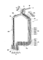
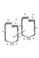
- FIG. 1 shows a cross-sectional view of the motor 100 of the present embodiment.
- the motor 100 includes a rotor 40 having a shaft 41 and a rotor core 43, and a stator 10 having a stator core 13 into which a coil rod 12 is inserted. As shown in FIG. 1, one end of the coil rod 12 is bent in the axial direction of the motor 100.
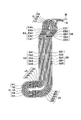
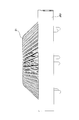
- FIG. 3 shows a perspective view of the coil 11.
- FIG. 4 shows a front view of the coil 11.
- FIG. 5 shows a top view of the coil 11.
- FIG. 6 shows a side view of the coil 11.
- the coil 11 used for the coil cage 12 is a concentric coil 11 formed by winding a flat conductor D.
- the flat rectangular conductor D is obtained by applying an insulating coating around a highly conductive metal such as copper having a rectangular cross section.
- the coil 11 includes an in-slot conductor part SA and an in-slot conductor part SB disposed in the slot.
- the in-slot conductor portion SA is obtained by overlapping the five flat conductors D with the long side surfaces (flatwise surfaces) formed by the long sides of the rectangular cross section being in contact with each other. This is an assembly of the in-slot conductor part SA1, the second slot conductor part SA2, the third slot conductor part SA3, the fourth slot conductor part SA4, and the fifth slot conductor part SA5.
- the in-slot conductor portion SB is obtained by superimposing five flat rectangular conductors D in contact with long side surfaces (flatwise surfaces) constituted by long sides of a rectangular cross section.
- This is an assembly of the in-slot conductor SB1, the second slot conductor SB2, the third slot conductor SB3, the fourth slot conductor SB4, and the fifth slot conductor SB5.
- An upper concentric circle part G is formed at the center of the coil end part located on the upper side of the coil rod 12.
- the upper concentric circle part G is an aggregate of four rectangular conductors D including a second concentric circle part G2, a third concentric circle part G3, a fourth concentric circle part G4, and a fifth concentric circle part G5.
- the reason why the first concentric circle portion is not included is that a first inclined portion EA1 described later projects as a terminal M to the outer peripheral side of the coil rod 12.
- a bent part IA is formed at the upper end of the in-slot conductor part SA.
- the flat conductor D is bent by edgewise bending in the direction of the upper concentric circle G at the bent portion IA.
- An inclined portion EA is formed between the upper concentric circle portion G and the in-slot conductor portion SA.
- the bent portion IA is an aggregate of the first bent portion IA1, the second bent portion IA2, the third bent portion IA3, the fourth bent portion IA4, and the fifth bent portion IA5.
- the inclined portion EA is an aggregate of the first inclined portion EA1, the second inclined portion EA2, the third inclined portion EA3, the fourth inclined portion EA4, and the fifth inclined portion EA5.
- five rectangular conductors D are overlapped in the radial direction of the coil rod 12 (left and right direction in FIG. 6), as in the in-slot conductor portion SA, as shown in FIG.
- the bent portion IB is an aggregate of the first bent portion IB1, the second bent portion IB2, the third bent portion IB3, the fourth bent portion IB4, and the fifth bent portion IB5.
- the inclined portion EB is an aggregate of the first inclined portion EB1, the second inclined portion EB2, the third inclined portion EB3, the fourth inclined portion EB4, and the fifth inclined portion EB5.
- the inclined portion EB five flat conductors D are overlapped in the radial direction of the coil rod 12 (left and right direction in FIG. 6), as in the in-slot conductor portion SB, as shown in FIG. Further, as shown in FIG. 6, the terminal M of the first inclined portion EA1 located at the innermost peripheral portion of the inclined portion EA is bent and protrudes toward the outer peripheral side of the coil rod 12. Further, the terminal N of the fifth inclined portion EB5 located on the outermost periphery of the inclined portion EB is bent and protrudes toward the outer peripheral side of the coil rod 12.
- a bent portion JA is formed at the lower end of the in-slot conductor portion SA.
- the bent portion JA is an aggregate of the first bent portion JA1, the second bent portion JA2, the third bent portion JA3, the fourth bent portion JA4, and the fifth bent portion JA5.
- a bent portion JB is formed at the lower end of the in-slot conductor SB.
- the flat conductor D is bent 90 degrees on the inner peripheral side (left direction in FIG. 6) at the bent portion JB.
- the bent portions JB are the first bent portion JB1, the second bent portion JB2, the third bent portion JB3, the fourth bent portion JB4, and the fifth bent portion JB5 of the five flat conductors D. Is a collection of
- a lower concentric circle H is formed at the inner peripheral side end of the coil rod 12. As shown in FIG. 4, a horizontal portion FA is formed between the bent portion JA and the lower concentric circle portion H. A horizontal part FB is formed between the bent part JB and the lower concentric part H. As shown in FIG. 6, the lower concentric part H includes a first lower concentric part H1, a second lower concentric part H2, a third lower concentric part H3, a fourth lower concentric part H4, and a fifth lower part. This is an assembly of side concentric circles H5.
- the horizontal portion FA is an aggregate of the first horizontal portion FA1, the second horizontal portion FA2, the third horizontal portion FA3, the fourth horizontal portion FA4, and the fifth horizontal portion FA5.
- the horizontal portion FA the horizontal portions of the five rectangular conductors D are overlapped in the axial direction of the coil rod 12 (vertical direction in FIG. 4) as shown in FIG.
- the horizontal portion FB is an aggregate of the first horizontal portion FB1, the second horizontal portion FB2, the third horizontal portion FB3, the fourth horizontal portion FB4, and the fifth horizontal portion FB5.
- the horizontal portions of the five flat conductors D are overlapped in the axial direction of the coil rod 12 (up and down direction in FIG. 4) as shown in FIG.
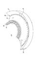
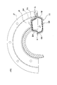
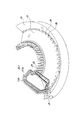
- FIG. 7 shows a plan view of the tapered jig.
- FIG. 8 is a perspective view of the tapered jig.
- the tapered jig JG1 has a semicircular shape, and as shown in FIGS. 7 and 8, the outer peripheral portion J1 and the tapered portion J2, the upper inner peripheral positioning pin J3 and the upper outer peripheral positioning pin J4, and the lower small positioning pin J5. And a lower large positioning pin J6, a retracting portion J7, and a connecting portion J8.
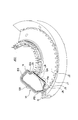
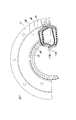
- FIG. 9 shows a plan view of the coil 11 placed on the tapered jig JG1.
- FIG. 10 is a perspective view showing a state in which the coil 11 is disposed on the tapered jig JG1.
- the coil 11 is arranged with the lower concentric part H side facing the inner peripheral side of the outer peripheral part J1.
- the in-slot conductor SA of the coil 11 is arranged so as to be sandwiched between the upper inner peripheral positioning pin J3 and the upper outer peripheral positioning pin J4, and the upper inner peripheral positioning pin J3 is in contact with the inner peripheral side of the bent portion IA.
- the lower small positioning pin J5 is arranged on the side surface of the upper concentric circle part G.
- a terminal M, a terminal N, and an upper concentric part G are disposed on the outer peripheral part J1.
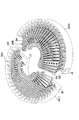
- FIG. 11 shows a plan view of a state in which a plurality of coils 11 are arranged on the tapered jig JG1.
- FIG. 12 is a perspective view showing a state in which the plurality of coils 11 are arranged on the tapered jig JG1.
- a new coil 11 is arranged on the coil 11 already arranged in the tapered jig JG1.
- the first coil 11 that is disposed is referred to as a first coil 11A
- the coil 11 that is disposed on the first coil 11A is referred to as a second coil 11B.
- the semi-annular coil 20 is formed on the tapered jig JG1 by sequentially stacking the coils 11.
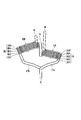
- FIG. 13 is a perspective view showing a state in which the semicircular coil is arranged on the tapered jig JG1.
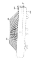
- FIG. 14 the side view showing a mode that the semi-annular coil 20 is arrange
- a first semicircular coil rod 20A is disposed on the first tapered jig JG11
- a second semicircular coil rod 20B is disposed on the second tapered jig JG12.
- the in-slot portion SA of the first semicircular coil rod 20A and the in-slot portion SB of the second tapered jig JG12 protrude from the first tapered jig JG11 and the second tapered jig JG12, respectively. Yes.
- the second tapered jig JG12 is inclined by the angle ⁇ with respect to the first tapered jig JG11.
- the angle ⁇ is 1 to 2 degrees.
- a retracting portion J7 is formed in the tapered jig JG1. In this state, the first tapered jig JG11 and the second tapered jig JG12 are brought close to each other.
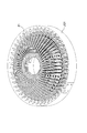
- FIG. 15 is a perspective view showing a state where the annular assembly 21 is arranged on the tapered jig JG1.
- FIG. 16 is a side view showing a state where the annular assembly 21 is arranged on the tapered jig JG1.
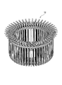
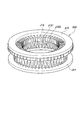
- FIG. 17 shows a perspective view of the ring-shaped jig JG2.
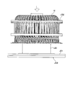
- FIG. 18 shows a side view of the ring-shaped jig inserted into the coil cage.
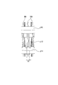
- FIG. 19 is an enlarged view showing a state when the ring-shaped jig JG2 is inserted into the coil cage 12.
- the ring-shaped jig JG2 is provided with an upper ring J10, a lower ring J11, and comb teeth J12 formed by connecting them and projecting toward the inner peripheral side.
- the comb tooth J12 is provided with a tapered portion J122 that is formed in a narrow wedge shape from the upper ring J10 side toward the lower ring J11 side.
- FIG. 19 shows a tapered portion J122 that is formed in a narrow wedge shape from the upper ring J10 side toward the lower ring J11 side.
- the parallel part J121 is formed in the part which protrudes in the inner peripheral side of the comb-tooth J12.
- the support jig JG3 is provided with a support J20.
- the column J20 has a structure that supports the inner periphery of the coil 11 at the top of the head.
- the annular assembly 21 placed on the tapered jig JG1 is inserted into the support J20 from the upper surface side of the support jig JG3, and the lower concentric part H of the annular assembly 21 is provided.
- the ring-shaped jig JG2 is inserted from the side provided with. Insertion of the ring-shaped jig JG2 is a process in which the annular assembly 21 is formed into the shape of the coil cage 12, and the comb teeth J12 are inserted between the in-slot conductors SB as shown in FIG. There is a function of aligning the interval between the inner conductor portion SA and the slot conductor portion SB.
- the ring-shaped jig JG2 is inserted, and the taper-shaped jig JG1 is removed from the annular assembly 21 so as to be close to the base J21 side of the columnar jig JG3.
- the coil cage 12 is formed on the support jig JG3.
- the motor 100 is formed by assembling the coil rod 12 thus formed to the stator core 13 and inserting the rotor 40.
- the stator core 13 is not shown and described as a single unit, the stator core 13 is formed by laminating electromagnetic steel sheets punched into a donut shape by pressing, and teeth protrude from the inner peripheral side of the stator core 13, and adjacent teeth are formed.
- a slot into which the in-slot conductor part SA or the in-slot conductor part SB is inserted is prepared between them.
- the number of teeth is 48, and the same number of slots as the teeth are prepared.
- the stator 10 is formed by inserting the coil rod 12 into the stator core 13 from the axial direction.
- the motor 100 is formed by inserting the rotor 40 from the one coil end side of the stator 10 and the opposite side of the side where the lower concentric part H of the coil rod 12 is disposed.
- a shaft 41 provided in the rotor 40 is rotatably held by a bearing (not shown), and a casing to which the bearing is fixed is fixed to the stator core 13.
- the manufacturing method of the motor 100 of the present embodiment uses the motor 100 having the stator 10 having the distributed winding coil 11 using the flat rectangular conductor D and the stator core 13 and the rotor 40 having the central axis as the distributed winding coil 11.
- the motor manufacturing method of manufacturing the motor 100 by forming the coil rod 12 in combination and inserting the coil rod 12 into the stator core 13 from the axial direction, the coil end portion at one end of the coil 11 is the in-slot conductor portion of the stator core 13.
- the coils 11 are sequentially placed on the first taper jig JG11 and the second taper jig JG12 which are formed to be bent toward the rotor 40 with respect to the SA and the in-slot conductor portion SB and have slopes on which the coil 11 is disposed.
- the first semi-annular coil cage 20A and the second semi-annular coil cage 20 0B is formed, and the second tapered jig JG12 is brought close to and coupled to the first tapered jig JG11 (or just abutting), so that the coil 11 is arranged in an annular shape.
- An annular assembly 21 in which the first semicircular coil rod 20A and the second semicircular coil rod 20B are combined is formed, and the first tapered jig JG11 and the second tapered jig JG12 are annularly assembled. Simultaneously withdrawing from the other end side of the coil 11 from the body 21, the ring-shaped jig JG 2 is inserted from one end side of the coil 11 of the annular assembly 21 to form the coil rod 12, and the stator core from one end side of the coil 11 13 to be inserted.
- FIG. 20 is a schematic diagram for explaining the interference in the axial direction.
- FIG. 21 is a schematic diagram for explaining the interference in the radial direction.
- the coil 11 on the side that is held without moving will be referred to as a first coil 11A
- the coil 11 on the side that is assembled close to the first coil 11A will be described as a second coil 11B.
- the inclined portion EB has a shape that is disposed on the outer peripheral side (upper side in FIG. 5) of the coil rod 12 with respect to the horizontal portion FA.
- the horizontal portion FA and the inclined portion EB interfere with each other.
- FIG. 22 is a plan view showing how the coils 11 are assembled together in the circumferential direction of the coil cage 12.
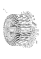
- FIG. 23 the perspective view of the coil cage
- a coil rod 12 in a state where 42 coils 11 are assembled is shown in FIG. 16. Due to the shape of the coil 11, the 37th slot internal conductor SA37 to the 42th slot internal conductor SA42 are provided in the first slot. It arrange
- the first semicircular coil rod 20A and the second semicircular coil rod 20B are formed, and the first semicircular coil rod 20B is formed.
- the annular coil rod 20A and the second semi-annular coil rod 20B are assembled to face each other.
- the first semi-annular coil rod 20A and the second semi-annular coil rod 20B are formed by overlapping the semicircle, that is, the 24 coils 11, and thus can be formed without difficulty.
- the first semi-annular coil rod 20A is formed on the first tapered jig JG11 as described above.
- the second semicircular coil rod 20B is formed on the second tapered jig JG12.
- the coils 11 are sequentially stacked to prevent interference between the coils 11.
- the first semicircular coil rod 20A and the second semicircular coil rod 20B can be assembled without interference, and the second taper jig JG12 is inclined by an angle ⁇ with respect to the first taper jig JG11.
- the annular assembly 21 can be formed.
- the coil 11 can be easily held in terms of the shape characteristics, compared with the case where the coil 11 is assembled in an upright state. This is because the coil 11 has a shape as shown in FIG. 6 and when the lower concentric part H is held in the state as shown in FIG. It is necessary to support so as not to fall in the outer peripheral direction (right direction in FIG. 6).
- the method of holding the lower concentric circle portion H or supporting the in-slot conductor portion SB is likely to be unstable, and the assembly direction needs to be the circumferential direction of the coil rod 12, so that the support portion, etc. It is difficult to form so as not to interfere.
- the method of disposing the taper jig JG1 so as to lean against the taper portion J2 is easy to stabilize and the coils 11 are easily stacked.
- the coil 11 is simply stacked while being shifted in the circumferential direction of the tapered jig JG1, and the workability is also good.
- the first semi-annular coil cage 20A and the second semi-annular coil cage 20B are assembled.
- the coils 11 at both ends correspond to the assembly of the coil rod 12 from the circumferential direction as shown in FIG. 22, the assembly is possible.
- the same state as the state in which the coils 11 are assembled from the circumferential direction can be obtained, and 48 coils 11 can be assembled to the coil cage 12.
- the second taper jig JG12 is inclined by an angle ⁇ with respect to the first taper jig JG11, and the retracting portion J7 is provided in the first taper jig JG11 and the second taper jig JG12, so that the coil
- the first semicircular coil rod 20A and the second semicircular coil rod 20B can be assembled without interfering with each other.
- the ring-shaped jig JG2 has a conductor width St of the in-slot conductor SB formed between adjacent comb teeth J12.
- the conducting wire width St is an interval between adjacent comb teeth J12 on the upper ring J10 side.
- the in-slot conductor portion SA and the in-slot conductor portion SB are inserted so that the comb teeth J12 are accommodated in the same slot from the lower concentric circle portion H side.
- the conducting wire portion SB is aligned by the taper portion J122, and the in-slot conducting wire portion SA and the in-slot conducting wire portion SB are arranged at predetermined positions by the parallel portion J121 having the conducting wire width St.
- the coil rod 12 can be easily inserted into the stator core 13. Therefore, the assemblability of the stator 10 can be improved.
- the materials exemplified in this embodiment are not prevented from being replaced as appropriate, and the number of turns of the coil 11, the number of slots in the stator core 13, or the number of coils 11 used in the coil rod 12 is prevented from being changed depending on the design specifications. Absent.
Landscapes
- Engineering & Computer Science (AREA)
- Manufacturing & Machinery (AREA)
- Power Engineering (AREA)
- Manufacture Of Motors, Generators (AREA)
Abstract
Selon l'invention, une partie extrémité de bobine d'une bobine (11) est formée de manière courbée du côté d'un rotor (40) face à des parties fil conducteur interne d'encoche (SA, SB) d'un noyau de stator (13). Un premier panier de bobine de forme semi-circulaire (20A), et un second panier de bobine de forme semi-circulaire (20B) sont formés selon une disposition de manière semi-circulaire de chacun dans laquelle une bobine (11) est disposée dans l'ordre sur un gabarit en forme de bande (JG1) possédant une face inclinée sur laquelle est disposée la bobine (11). Un ensemble de forme circulaire (21) dans lequel la bobine (11) est disposée de manière circulaire, est formé par la mise en contact d'un second gabarit en forme de bande (JG12) avec un premier gabarit en forme de bande (JG11). Simultanément au retrait du gabarit en forme de bande (JG1) de l'autre côté extrémité de la bobine (11) par l'ensemble de forme circulaire (21), un gabarit en forme d'anneau (JG2) est introduit par le côté première extrémité de la bobine (11) de l'ensemble de forme circulaire (21), formant ainsi un panier de bobine (12), et introduisant le noyau de stator (13) par le côté première extrémité de la bobine (11).
Priority Applications (2)
| Application Number | Priority Date | Filing Date | Title |
|---|---|---|---|
| JP2011536674A JP5278553B2 (ja) | 2011-03-08 | 2011-03-08 | モータ製造方法 |
| PCT/JP2011/055394 WO2012120646A1 (fr) | 2011-03-08 | 2011-03-08 | Procédé de fabrication de moteur |
Applications Claiming Priority (1)
| Application Number | Priority Date | Filing Date | Title |
|---|---|---|---|
| PCT/JP2011/055394 WO2012120646A1 (fr) | 2011-03-08 | 2011-03-08 | Procédé de fabrication de moteur |
Publications (1)
| Publication Number | Publication Date |
|---|---|
| WO2012120646A1 true WO2012120646A1 (fr) | 2012-09-13 |
Family
ID=46797649
Family Applications (1)
| Application Number | Title | Priority Date | Filing Date |
|---|---|---|---|
| PCT/JP2011/055394 Ceased WO2012120646A1 (fr) | 2011-03-08 | 2011-03-08 | Procédé de fabrication de moteur |
Country Status (2)
| Country | Link |
|---|---|
| JP (1) | JP5278553B2 (fr) |
| WO (1) | WO2012120646A1 (fr) |
Cited By (6)
| Publication number | Priority date | Publication date | Assignee | Title |
|---|---|---|---|---|
| WO2014061406A1 (fr) * | 2012-10-15 | 2014-04-24 | 日立オートモティブシステムズ株式会社 | Machine dynamo-électrique |
| CN106921224A (zh) * | 2017-03-30 | 2017-07-04 | 威灵(芜湖)电机制造有限公司 | 定子总成及其成型方法、电机及其成型方法和转子 |
| CN109746345A (zh) * | 2018-12-30 | 2019-05-14 | 苏州阿福机器人有限公司 | 一种用于扁线电机绕组中扁线折弯的装置 |
| CN113783384A (zh) * | 2020-06-09 | 2021-12-10 | Seg汽车德国有限公司 | 用于制造电的机器的转子的绕组的方法 |
| WO2024104530A1 (fr) * | 2022-11-18 | 2024-05-23 | Schaeffler Technologies AG & Co. KG | Magasin linéaire et kit de pièces |
| JP7887560B1 (ja) * | 2025-12-04 | 2026-07-09 | 三工機器株式会社 | セグメントコイルユニットの製造方法及びその製造装置 |
Families Citing this family (2)
| Publication number | Priority date | Publication date | Assignee | Title |
|---|---|---|---|---|
| KR102257124B1 (ko) * | 2020-08-21 | 2021-05-27 | (주)디케이텍인더스트리 | 헤어핀 가정렬 장치 |
| KR102854853B1 (ko) * | 2021-01-28 | 2025-09-03 | 현대자동차 주식회사 | 헤어핀 타입 고정자 코일의 얼라인 장치 |
Citations (3)
| Publication number | Priority date | Publication date | Assignee | Title |
|---|---|---|---|---|
| JPS5619363A (en) * | 1979-07-19 | 1981-02-24 | Matsushita Electric Ind Co Ltd | Inserting method for coil winding and inserting device for coil winding |
| JP2009195007A (ja) * | 2008-02-14 | 2009-08-27 | Hitachi Ltd | コイル、及び回転電機、並びに回転電機の製造方法 |
| JP2010226862A (ja) * | 2009-03-23 | 2010-10-07 | Aisin Aw Co Ltd | ステータの製造装置 |
Family Cites Families (2)
| Publication number | Priority date | Publication date | Assignee | Title |
|---|---|---|---|---|
| JP5363403B2 (ja) * | 2010-04-19 | 2013-12-11 | トヨタ自動車株式会社 | モータ |
| JP5292360B2 (ja) * | 2010-06-10 | 2013-09-18 | トヨタ自動車株式会社 | モータ |
-
2011
- 2011-03-08 WO PCT/JP2011/055394 patent/WO2012120646A1/fr not_active Ceased
- 2011-03-08 JP JP2011536674A patent/JP5278553B2/ja not_active Expired - Fee Related
Patent Citations (3)
| Publication number | Priority date | Publication date | Assignee | Title |
|---|---|---|---|---|
| JPS5619363A (en) * | 1979-07-19 | 1981-02-24 | Matsushita Electric Ind Co Ltd | Inserting method for coil winding and inserting device for coil winding |
| JP2009195007A (ja) * | 2008-02-14 | 2009-08-27 | Hitachi Ltd | コイル、及び回転電機、並びに回転電機の製造方法 |
| JP2010226862A (ja) * | 2009-03-23 | 2010-10-07 | Aisin Aw Co Ltd | ステータの製造装置 |
Cited By (9)
| Publication number | Priority date | Publication date | Assignee | Title |
|---|---|---|---|---|
| WO2014061406A1 (fr) * | 2012-10-15 | 2014-04-24 | 日立オートモティブシステムズ株式会社 | Machine dynamo-électrique |
| CN106921224A (zh) * | 2017-03-30 | 2017-07-04 | 威灵(芜湖)电机制造有限公司 | 定子总成及其成型方法、电机及其成型方法和转子 |
| CN106921224B (zh) * | 2017-03-30 | 2019-03-08 | 威灵(芜湖)电机制造有限公司 | 定子总成及其成型方法、电机及其成型方法和转子 |
| CN109746345A (zh) * | 2018-12-30 | 2019-05-14 | 苏州阿福机器人有限公司 | 一种用于扁线电机绕组中扁线折弯的装置 |
| CN109746345B (zh) * | 2018-12-30 | 2024-03-22 | 苏州阿福机器人有限公司 | 一种用于扁线电机绕组中扁线折弯的装置 |
| CN113783384A (zh) * | 2020-06-09 | 2021-12-10 | Seg汽车德国有限公司 | 用于制造电的机器的转子的绕组的方法 |
| WO2024104530A1 (fr) * | 2022-11-18 | 2024-05-23 | Schaeffler Technologies AG & Co. KG | Magasin linéaire et kit de pièces |
| DE102022130531A1 (de) * | 2022-11-18 | 2024-05-23 | Schaeffler Technologies AG & Co. KG | Linearmagazin und Kit-of-parts |
| JP7887560B1 (ja) * | 2025-12-04 | 2026-07-09 | 三工機器株式会社 | セグメントコイルユニットの製造方法及びその製造装置 |
Also Published As
| Publication number | Publication date |
|---|---|
| JP5278553B2 (ja) | 2013-09-04 |
| JPWO2012120646A1 (ja) | 2014-07-07 |
Similar Documents
| Publication | Publication Date | Title |
|---|---|---|
| JP5278553B2 (ja) | モータ製造方法 | |
| JP5278555B2 (ja) | モータ製造方法 | |
| KR101326477B1 (ko) | 모터 및 모터 제조 방법 | |
| JP5292360B2 (ja) | モータ | |
| CN104362783B (zh) | 旋转电机的定子、定子的制造方法、以及定子的线圈的制造方法 | |
| US10594182B2 (en) | Stator manufacturing method and stator | |
| JP5278546B2 (ja) | ステータ | |
| JP5924711B2 (ja) | 電気機械用電機子巻線に用いられる巻線体の製造方法 | |
| CN104067491B (zh) | 线圈的制造方法 | |
| US9009948B2 (en) | Method of manufacturing stator coil for electric rotating machine | |
| CN101888126B (zh) | 定子线圈及其制造方法 | |
| JP5952701B2 (ja) | モータのステータ構造、ブラシレスモータ、およびモータのステータ構造の製造方法 | |
| JP2012222903A (ja) | ステータの製造方法及び製造装置 | |
| JP4443286B2 (ja) | 回転電動機の固定子、回転電動機のコイル装着方法、コイル巻線機 | |
| CN107925321B (zh) | 电枢的制造方法 | |
| CN116707235A (zh) | 用于形成定子绕组端匝的互锁工具 | |
| JP2012235544A (ja) | モータ製造方法、モータ | |
| JP2019205230A (ja) | 回転電機の固定子の製造方法 | |
| JP2013021858A (ja) | モータ製造方法 | |
| JP2008054377A (ja) | 積層鉄心の製造方法 | |
| WO2005064768A1 (fr) | Moteur sans fente et son procede de production |
Legal Events
| Date | Code | Title | Description |
|---|---|---|---|
| ENP | Entry into the national phase |
Ref document number: 2011536674 Country of ref document: JP Kind code of ref document: A |
|
| 121 | Ep: the epo has been informed by wipo that ep was designated in this application |
Ref document number: 11860178 Country of ref document: EP Kind code of ref document: A1 |
|
| NENP | Non-entry into the national phase |
Ref country code: DE |
|
| 122 | Ep: pct application non-entry in european phase |
Ref document number: 11860178 Country of ref document: EP Kind code of ref document: A1 |