WO2012120714A1 - Palette de transport - Google Patents
Palette de transport Download PDFInfo
- Publication number
- WO2012120714A1 WO2012120714A1 PCT/JP2011/072102 JP2011072102W WO2012120714A1 WO 2012120714 A1 WO2012120714 A1 WO 2012120714A1 JP 2011072102 W JP2011072102 W JP 2011072102W WO 2012120714 A1 WO2012120714 A1 WO 2012120714A1
- Authority
- WO
- WIPO (PCT)
- Prior art keywords
- support base
- sub
- main support
- substrate
- panel
- Prior art date
- Legal status (The legal status is an assumption and is not a legal conclusion. Google has not performed a legal analysis and makes no representation as to the accuracy of the status listed.)
- Ceased
Links
Images



Classifications
-
- B—PERFORMING OPERATIONS; TRANSPORTING
- B65—CONVEYING; PACKING; STORING; HANDLING THIN OR FILAMENTARY MATERIAL
- B65D—CONTAINERS FOR STORAGE OR TRANSPORT OF ARTICLES OR MATERIALS, e.g. BAGS, BARRELS, BOTTLES, BOXES, CANS, CARTONS, CRATES, DRUMS, JARS, TANKS, HOPPERS, FORWARDING CONTAINERS; ACCESSORIES, CLOSURES, OR FITTINGS THEREFOR; PACKAGING ELEMENTS; PACKAGES
- B65D19/00—Pallets or like platforms, with or without side walls, for supporting loads to be lifted or lowered
- B65D19/38—Details or accessories
- B65D19/44—Elements or devices for locating articles on platforms
-
- B—PERFORMING OPERATIONS; TRANSPORTING
- B65—CONVEYING; PACKING; STORING; HANDLING THIN OR FILAMENTARY MATERIAL
- B65D—CONTAINERS FOR STORAGE OR TRANSPORT OF ARTICLES OR MATERIALS, e.g. BAGS, BARRELS, BOTTLES, BOXES, CANS, CARTONS, CRATES, DRUMS, JARS, TANKS, HOPPERS, FORWARDING CONTAINERS; ACCESSORIES, CLOSURES, OR FITTINGS THEREFOR; PACKAGING ELEMENTS; PACKAGES
- B65D21/00—Nestable, stackable or joinable containers; Containers of variable capacity
- B65D21/02—Containers specially shaped, or provided with fittings or attachments, to facilitate nesting, stacking, or joining together
-
- B—PERFORMING OPERATIONS; TRANSPORTING
- B65—CONVEYING; PACKING; STORING; HANDLING THIN OR FILAMENTARY MATERIAL
- B65D—CONTAINERS FOR STORAGE OR TRANSPORT OF ARTICLES OR MATERIALS, e.g. BAGS, BARRELS, BOTTLES, BOXES, CANS, CARTONS, CRATES, DRUMS, JARS, TANKS, HOPPERS, FORWARDING CONTAINERS; ACCESSORIES, CLOSURES, OR FITTINGS THEREFOR; PACKAGING ELEMENTS; PACKAGES
- B65D85/00—Containers, packaging elements or packages, specially adapted for particular articles or materials
- B65D85/30—Containers, packaging elements or packages, specially adapted for particular articles or materials for articles particularly sensitive to damage by shock or pressure
- B65D85/48—Containers, packaging elements or packages, specially adapted for particular articles or materials for articles particularly sensitive to damage by shock or pressure for glass sheets
-
- B—PERFORMING OPERATIONS; TRANSPORTING
- B65—CONVEYING; PACKING; STORING; HANDLING THIN OR FILAMENTARY MATERIAL
- B65D—CONTAINERS FOR STORAGE OR TRANSPORT OF ARTICLES OR MATERIALS, e.g. BAGS, BARRELS, BOTTLES, BOXES, CANS, CARTONS, CRATES, DRUMS, JARS, TANKS, HOPPERS, FORWARDING CONTAINERS; ACCESSORIES, CLOSURES, OR FITTINGS THEREFOR; PACKAGING ELEMENTS; PACKAGES
- B65D85/00—Containers, packaging elements or packages, specially adapted for particular articles or materials
- B65D85/68—Containers, packaging elements or packages, specially adapted for particular articles or materials for machines, engines or vehicles in assembled or dismantled form
-
- B—PERFORMING OPERATIONS; TRANSPORTING
- B65—CONVEYING; PACKING; STORING; HANDLING THIN OR FILAMENTARY MATERIAL
- B65D—CONTAINERS FOR STORAGE OR TRANSPORT OF ARTICLES OR MATERIALS, e.g. BAGS, BARRELS, BOTTLES, BOXES, CANS, CARTONS, CRATES, DRUMS, JARS, TANKS, HOPPERS, FORWARDING CONTAINERS; ACCESSORIES, CLOSURES, OR FITTINGS THEREFOR; PACKAGING ELEMENTS; PACKAGES
- B65D2519/00—Pallets or like platforms, with or without side walls, for supporting loads to be lifted or lowered
- B65D2519/00004—Details relating to pallets
- B65D2519/00258—Overall construction
- B65D2519/00283—Overall construction of the load supporting surface
- B65D2519/00293—Overall construction of the load supporting surface made of more than one piece
-
- B—PERFORMING OPERATIONS; TRANSPORTING
- B65—CONVEYING; PACKING; STORING; HANDLING THIN OR FILAMENTARY MATERIAL
- B65D—CONTAINERS FOR STORAGE OR TRANSPORT OF ARTICLES OR MATERIALS, e.g. BAGS, BARRELS, BOTTLES, BOXES, CANS, CARTONS, CRATES, DRUMS, JARS, TANKS, HOPPERS, FORWARDING CONTAINERS; ACCESSORIES, CLOSURES, OR FITTINGS THEREFOR; PACKAGING ELEMENTS; PACKAGES
- B65D2519/00—Pallets or like platforms, with or without side walls, for supporting loads to be lifted or lowered
- B65D2519/00004—Details relating to pallets
- B65D2519/00736—Details
- B65D2519/0081—Elements or devices for locating articles
- B65D2519/00815—Elements or devices for locating articles on the pallet
-
- B—PERFORMING OPERATIONS; TRANSPORTING
- B65—CONVEYING; PACKING; STORING; HANDLING THIN OR FILAMENTARY MATERIAL
- B65D—CONTAINERS FOR STORAGE OR TRANSPORT OF ARTICLES OR MATERIALS, e.g. BAGS, BARRELS, BOTTLES, BOXES, CANS, CARTONS, CRATES, DRUMS, JARS, TANKS, HOPPERS, FORWARDING CONTAINERS; ACCESSORIES, CLOSURES, OR FITTINGS THEREFOR; PACKAGING ELEMENTS; PACKAGES
- B65D2519/00—Pallets or like platforms, with or without side walls, for supporting loads to be lifted or lowered
- B65D2519/00004—Details relating to pallets
- B65D2519/00736—Details
- B65D2519/00935—Details with special means for nesting or stacking
- B65D2519/00955—Details with special means for nesting or stacking stackable
- B65D2519/00965—Details with special means for nesting or stacking stackable when loaded
- B65D2519/0097—Details with special means for nesting or stacking stackable when loaded through corner posts
Definitions
- the present invention relates to a transport pallet for transporting a load such as a panel.
- a transport pallet for transporting a panel includes a substrate 101 and a presser 104. This is a method of placing the panel P on the substrate 101 and forcing the substrate 101 to a forklift. It was transported by gripping it with a transport device such as.
- the substrate 101 is approximately the same size as the panel P, and a pressing tool 104 is attached around the substrate 101 so that the panel P does not move.
- a support base plate-like body placement member
- a pressing tool movement limiting member
- the present invention has been made in view of the above circumstances, and an object thereof is to provide a transport pallet capable of transporting loads of different sizes.
- a transport pallet includes a substrate, a main support base, a sub-support base, and a presser, and the main support base is provided on the substrate and mounts a load.
- the sub-support base is larger than the main support base and surrounds the main support base.
- the height of the sub-support base is equal to or higher than the height of the main support base.
- the retainer is attached around the main support when the sub-support is removed, and is attached around the sub-support when the sub-support is installed, and supports the load from the horizontal direction. It is a thing to do.
- attaching the presser to the periphery of the main support base or sub-support base means attaching to the periphery of the main support base or sub-support base, or mounting on the substrate around the main support base or sub-support base. Including both.
- the presser is attached to the side surface of the main support base when the sub support base is removed, and attached to the side face of the sub support base when the sub support base is attached. It is characterized by.
- the conveyance pallet according to the third aspect of the present invention is characterized in that the sub-support base covers the main support base from above.
- the transport pallet according to the fourth aspect of the present invention is provided with columns on the substrate, and other substrates can be stacked on the columns.
- the lower surface of the upper substrate is It is characterized by being higher than the upper end of a presser attached around the sub-support on the lower substrate.
- the transport pallet when a presser is attached around the main support base (corresponding to a small panel), a sub support base surrounding the main support base is attached, When using a pressing tool attached to the periphery of the support base (corresponding to a large panel), it is possible to correspond to a panel having a different size. Since a single substrate is used in common, the cost is reduced and a large storage space is not required.
- the fixing part of the presser is close to the part where the panel load is applied to the presser, so that the structure is stronger. Further, by attaching the pressing tool to the sub-supporting base, the sub-supporting base can be enlarged to substantially the same size as the substrate.
- the sub-support base covers and attaches the main support base, and the upper surface can be formed flush with the panel, so that the panel is placed thereon. In addition, the panel will not be damaged.
- a plurality of substrates can be stacked in a state where the sub-support is used. Since the height of the main support is equal to or less than the height of the sub-support, if it can be stacked when the sub-support is used, it can naturally be stacked when the main support is used.
- FIG. 1st embodiment of the conveyance pallet of this invention shows the case where a main support stand is used, (b) shows the case where a sub support stand is used.
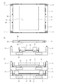
- A) is a plan view of the transport pallet,
- (b) is a side view when the main support is used, and
- (c) is a side view when the sub-support is used and the substrates are stacked. .
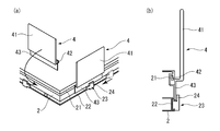
- the attachment part of a pressing tool is demonstrated,
- (a) is a perspective view,
- (b) is sectional drawing.
- It is a perspective view of 2nd embodiment of the conveyance pallet of this invention shows the case where a main support stand is used, (b) shows the case where a sub-support stand is used.
- FIG. 3rd embodiment of the conveyance pallet of this invention shows the case where a main support stand is used, (b) shows the case where a sub support stand is used. It is a perspective view of the attachment part of the pressing tool of 3rd embodiment. It is a side view of 4th embodiment of the conveyance pallet of this invention, (a) is a case where a main support stand is used, (b) is a case where an inner sub-support stand is used, (c) is an outer sub-support stand. Indicates when to use. It is a perspective view of the conventional conveyance pallet.
- the transport pallet of the present invention can transport various loads, but here, it is assumed that thin glass panels are stacked and transported.
- the first embodiment of the transport pallet includes a substrate 1, a main support base 2, a sub support base 3, and a presser 4.
- the substrate 1 has a rectangular flat plate shape, and has pillars 11 for stacking at the four corners of the upper surface, and fork holes 12 for inserting forks such as a forklift on the side surface.
- the main support 2 is a rectangular flat plate, is substantially the same size as the panel P1 to be transported, is smaller than the substrate 1, and is fixed to the center of the upper surface of the substrate 1 so as not to be detached.
- the sub-support base 3 has a rectangular flat plate shape, is substantially the same size as the panel P2 to be transported (larger than the panel P1), has a rectangular insertion hole 31 formed in the center, and has an insertion hole 31 on the upper surface.
- the surface material 32 is attached so as to cover the surface.
- the sub-support base 3 is higher than the main support base 2 and the insertion hole 31 is formed larger than the main support base 2, the sub-support base 3 is placed on the substrate from above the main support base 2. 1, the main support base 2 is accommodated in the insertion hole 31, and the main support base 2 is covered by the sub-support base 3.
- substantially L-shaped brackets 33 are attached (four on each side), and the brackets 33 can be fixed to the substrate 1 with screws.
- the presser 4 is substantially flat and can be attached to either the side surface of the main support base 2 or the side surface of the sub support base 3. In any case, a total of eight, two on each side, are attached and extend upward from the side to support the panel from the horizontal.
- the column 11 provided on the substrate 1 is higher than the presser 4 when the sub-support 3 is attached to the substrate 1 and the presser 4 is attached to the sub-support 3 (FIG. 2 (c). )).
- the presser 4 has a substantially flat plate shape, a presser piece 41 extending upward, a substantially L-shaped claw portion 42 extending inwardly from the lower end of the presser piece 41, and downward from the lower end of the presser piece 41. And a drooping piece 43 extending in the direction.
- an engaging groove 21 is formed along the longitudinal direction above the side surface of the main support 2 so that the claw portion 42 of the presser 4 can be engaged.
- a mounting groove 22 is formed along the longitudinal direction below the side surface, a stopper 23 is slidably mounted, and the stopper 23 has a locking piece 24 extending upward.
- the claw portion 42 of the presser 4 is engaged with the engagement groove 21, the hanging piece 43 is brought into contact with the side surface of the main support base 2, and the stopper 23 is slid. Since the hanging piece 43 can be fixed by being moved and sandwiched between the side surface of the main support base 2 and the locking piece 24, the attachment is easy. And if the stopper 23 is slid and the locking piece 24 is detached from the hanging piece 43, it can be easily removed.
- the side surface of the sub support stand 3 is also the same structure as the side surface of the main support stand 2, and the presser 4 can be attached and detached in the same manner.
- the presser 4 is attached to the side surface of the main support base 2 as shown in FIG. Although the panel P1 is mounted on the upper surface of the main support base 2, the upper surface of the main support base 2 is flush with the panel P1, so that the panel P1 is not damaged. And the panel P1 is conveyed from the periphery by the pressing tool 4, and is conveyed.
- the presser 4 is removed from the main support base 2 and the sub support base 3 is placed on the substrate 1 from above the main support base 2, as shown in FIG.
- the panel P2 mounts and covers the main support stand 2, and attaches the pressing tool 4 to the side surface of the sub support stand 3, and uses it.
- the panel P2 is placed on the upper surface of the sub-support base 3, but the upper surface of the sub-support base 3 is flush with the panel P2, so that the panel P2 is not damaged. And the panel P2 is conveyed from the periphery by the pressing tool 4, and is conveyed.
- this transport pallet can stack other substrates 1 on the pillars 11 provided at the four corners on the substrate 1.
- the pillar 11 is higher than the presser 4 attached to the sub-support base 3, so that a plurality of substrates 1 are mounted with the panel P 2 placed on the sub-support base 3. Can be stacked.
- the main support base 2 is covered with the sub support base 3, and the main support base 2 is lower than the sub support base 3, and the upper end of the presser 4 attached to the main support base 2 is also attached to the sub support base 3. Since it does not become higher than the upper end of the attached presser 4, if it can be stacked when the sub-support base 3 is used, it can naturally be stacked when the main support base 2 is used.
- the sub support base is attached from above the main support base,
- a pressing tool attached to the sub-support base corresponding to a large panel
- the main support base is formed so that the upper surface is flush with the main support base, and the sub-support base is attached so as to cover the main support base. The panel will not be damaged when placed.
- the pressing tool can be easily attached and detached by simply sliding the stopper, switching between the case of using the main support base and the case of using the sub support base is also easy. Moreover, since the fixing part (lower part of a pressing tool) becomes close to the location (upper part of a pressing tool) where the load of a panel is applied with respect to a pressing tool, it becomes a stronger structure. Furthermore, since the pressing tool is attached to the sub-support base when the sub-support base is attached, the sub-support base can be enlarged to substantially the same size as the substrate. In addition, a plurality of substrates can be stacked in a state where the main support base or the sub support base is used.
- FIG. 4 shows a second embodiment of the transport pallet of the present invention.
- the second embodiment differs from the first embodiment in the configuration of the sub-support base 3, does not have a surface material, and is in a state where the insertion hole 31 is exposed.
- substrate 1, the main support stand 2, and the pressing tool 4 is the same as 1st embodiment, and when conveying the small panel P1, as shown to Fig.4 (a), the panel P1 is a main support stand. 2 is placed on the upper surface.
- the sub-support base 3 is placed on the substrate 1 so as to surround the main support base 2 as shown in FIG.
- the main support base 2 is accommodated in the insertion hole 31 of the sub support base 3, and the upper surface of the main support base 2 and the upper surface of the sub support base 3 become the same height, and the area of the main support base 2 is enlarged by the sub support base 3.
- the A certain level difference or gap may occur between the main support base 2 and the sub support base 3, but if the panel P2 to be placed is not damaged by the level difference or gap, the second embodiment Forms are available.
- the second embodiment can cope with panels of different sizes, and since a single substrate is used in common, the cost is reduced and a large storage space is not required.
- FIG.5 and FIG.6 3rd embodiment of the conveyance pallet of this invention is shown.
- the third embodiment is different from the first and second embodiments in the configuration of the presser 4, and the presser 4 is placed on the upper surface of the substrate 1 when the sub-support 3 is detached and attached. Fix it. Therefore, it is assumed that the sub-support base 3 is smaller than the substrate 1 and that there is room for mounting the pressing tool 4 on the substrate 1 with the sub-support base 3 attached.
- the presser 4 has a substantially flat plate-like presser piece 41 that extends upward, a contact piece 44 that extends inward from the lower end of the presser piece 41 and that is bent in the middle and extends downward, and extends outward from the lower end of the contact piece 44.
- a grounding piece 45 is provided, and a rib 46 for joining the contact piece 44 and the grounding piece 45 is provided and reinforced.
- a through hole 48 for passing a bolt 47 is formed in the grounding piece 45, and the inner bolt hole 13 a is attached to the substrate 1 at a position corresponding to the removal of the sub support base 3 and the sub support base 3 is attached.
- the outer bolt hole 13b is formed at a location corresponding to the occasion, and the presser 4 is fixed to the substrate 1 by passing the bolt 47 through the through hole 48 and screwing into the inner bolt hole 13a or the outer bolt hole 13b.
- substrate 1, the main support stand 2, and the sub support stand 3 is the same as 1st embodiment, and when conveying the small panel P1, as shown to Fig.5 (a), it is in the main support stand 2.
- the presser 4 is attached by bringing the contact piece 44 into contact, and the panel P 1 is placed on the upper surface of the main support 2.
- the presser 4 is removed from the substrate 1, and the sub-support base 3 is placed on the substrate 1 from the main support base 2 to provide main support.
- the table 2 is covered, the contact piece 44 is brought into contact with the sub-support table 3, the pressing tool 4 is attached, and the panel P 2 is placed on the upper surface of the sub-support table 3.
- the fixing method of the pressing tool 4 is not limited to bolting.
- a concave portion may be formed on one of the pressing tool 4 and the substrate 1 and a convex portion may be formed on the other to be fitted.
- FIG. 7 shows a fourth embodiment of the transport pallet of the present invention.
- the sizes of the main support base 2 and the sub support base 3 are different from those of the first embodiment, and the sub support base 3 has a size as shown in FIG. Two different ones are provided (inner sub-support base 3a and outer sub-support base 3b).
- substrate 1 and the pressing tool 4 is the same as 1st embodiment.
- the main support 2 is a rectangular flat plate, is substantially the same size as the panel P1 to be transported, is smaller than the substrate 1, and is fixed to the center of the upper surface of the substrate 1 so as not to be detached.
- the inner sub-support 3a has a rectangular flat plate shape, is substantially the same size as the transported panel P2 (larger than the panel P1), has a rectangular insertion hole 31a formed in the center, and is inserted on the upper surface.
- a surface material 32a is attached to cover the hole 31a and is flush with the surface material 32a.
- the inner sub-support base 3a is higher than the main support base 2 and the insertion hole 31a is formed larger than the main support base 2, as shown in FIG.
- a substantially L-shaped bracket 33a is attached around the inner sub-support base 3a, and the bracket 33a can be fixed to the substrate 1 with screws.
- the outer sub-support base 3b has a rectangular flat plate shape, is approximately the same size as the transported panel P3 (larger than the panel P2), has a rectangular insertion hole 31b formed at the center, and has an insertion hole on the upper surface.
- a surface material 32b is attached to cover 31b and is flush with the surface material.
- the outer sub-support base 3b is higher than the inner sub-support base 3a, and the insertion hole 31b is formed larger than the inner sub-support base 3a, as shown in FIG.
- the inner sub-support base 3a When the outer sub-support base 3b is placed on the substrate 1 from above the inner sub-support base 3a, the inner sub-support base 3a is received in the insertion hole 31b, and the inner sub-support base 3a is covered by the outer sub-support base 3b.
- a substantially L-shaped bracket 33b is attached around the outer sub-support base 3b, and the bracket 33b can be fixed to the substrate 1 with screws. By comprising in this way, it can respond to three types of panels. Further, since the main support base 2 and the inner sub-support base 3a are nested in the outer sub-support base 3b, a large storage space is not required. When the outer sub-support base 3b is used, the inner sub-support base 3a does not necessarily have to be stored in the insertion hole 31b. Further, three or more sub-supports may be provided.
- the present invention is not limited to the above embodiment.
- the main support base and the sub support base are not limited to rectangular shapes, and may have any shape.
- the pressing member may be a rod or the like, and the number can be appropriately increased or decreased.
- the column may not be made higher than the presser, but a recess may be formed on the lower surface of the substrate so that the upper end of the presser does not contact the lower surface of the substrate.
- the substrate may be transported by a roller conveyor, a belt conveyor or the like in addition to being transported by a forklift.
Landscapes
- Engineering & Computer Science (AREA)
- Mechanical Engineering (AREA)
- Pallets (AREA)
- Packaging Frangible Articles (AREA)
Abstract
L'invention concerne une palette de transport pouvant transporter des charges de différentes tailles. La palette de transport est dotée d'un plateau de base (1), d'une base de support principale (2), d'une base de support secondaire (3) et de moyens de retenue (4). La base de support principale (2) est disposée sur le substrat et porte les charges. La base de support secondaire (3) : est plus grande que la base de support principale (2), emprisonne la base de support principale (2), recouvre la base de support principale (2) par le dessus, peut être attachée sur le dessus du substrat (1) et en être détachée, et porte les charges. Les moyens de retenue (4) se fixent sur les côtés de la base de support principale (2) lorsque la base de support secondaire (3) est retirée ou se fixent sur les côtés de la base de support secondaire (3) lorsque celle-ci est attachée et maintiennent les charges dans la direction horizontale.
Priority Applications (2)
| Application Number | Priority Date | Filing Date | Title |
|---|---|---|---|
| KR1020137021086A KR20130103807A (ko) | 2011-03-10 | 2011-09-27 | 반송 팔레트 |
| CN201180069131XA CN103442991A (zh) | 2011-03-10 | 2011-09-27 | 搬运托盘 |
Applications Claiming Priority (4)
| Application Number | Priority Date | Filing Date | Title |
|---|---|---|---|
| JP2011-053471 | 2011-03-10 | ||
| JP2011053471 | 2011-03-10 | ||
| JP2011121998A JP5061321B2 (ja) | 2011-03-10 | 2011-05-31 | 搬送パレット |
| JP2011-121998 | 2011-05-31 |
Publications (1)
| Publication Number | Publication Date |
|---|---|
| WO2012120714A1 true WO2012120714A1 (fr) | 2012-09-13 |
Family
ID=46797700
Family Applications (1)
| Application Number | Title | Priority Date | Filing Date |
|---|---|---|---|
| PCT/JP2011/072102 Ceased WO2012120714A1 (fr) | 2011-03-10 | 2011-09-27 | Palette de transport |
Country Status (5)
| Country | Link |
|---|---|
| JP (1) | JP5061321B2 (fr) |
| KR (1) | KR20130103807A (fr) |
| CN (1) | CN103442991A (fr) |
| TW (1) | TW201236952A (fr) |
| WO (1) | WO2012120714A1 (fr) |
Cited By (1)
| Publication number | Priority date | Publication date | Assignee | Title |
|---|---|---|---|---|
| CN110834789A (zh) * | 2019-11-27 | 2020-02-25 | 京东方科技集团股份有限公司 | 全面屏托盘 |
Families Citing this family (6)
| Publication number | Priority date | Publication date | Assignee | Title |
|---|---|---|---|---|
| CN108945710A (zh) * | 2018-05-23 | 2018-12-07 | 彩虹集团有限公司 | 可叠放式水平放置架 |
| KR102039437B1 (ko) | 2018-11-28 | 2019-11-04 | 주식회사 한국페잇 | 유리 고정 팔레트 |
| CN109502138A (zh) * | 2018-11-29 | 2019-03-22 | 林春敏 | 可调式运输支架及工作方法 |
| CN112441309A (zh) * | 2019-08-29 | 2021-03-05 | 北京京东方茶谷电子有限公司 | 一种背光源承载装置 |
| CN110775415B (zh) * | 2019-11-12 | 2022-04-15 | 京东方科技集团股份有限公司 | 一种电子产品盛放托盘 |
| JP2022075354A (ja) * | 2020-11-06 | 2022-05-18 | 三菱電機株式会社 | 梱包装置 |
Citations (6)
| Publication number | Priority date | Publication date | Assignee | Title |
|---|---|---|---|---|
| JPH0314598U (fr) * | 1989-06-12 | 1991-02-14 | ||
| JP2000128272A (ja) * | 1998-10-29 | 2000-05-09 | Zeon Kasei Co Ltd | コンテナ |
| JP2002145266A (ja) * | 2000-11-10 | 2002-05-22 | Fuji Photo Film Co Ltd | 平版印刷版積載用パレット構造 |
| WO2007119320A1 (fr) * | 2006-03-17 | 2007-10-25 | Toyota Steel Center Co., Ltd. | Palette et procede de fixation d'articles de chargement utilisant une telle palette |
| JP2009154960A (ja) * | 2007-12-28 | 2009-07-16 | Asahi Glass Co Ltd | 板状体収納容器 |
| JP3165973U (ja) * | 2010-12-02 | 2011-02-10 | 旭硝子株式会社 | 板状体収納容器 |
Family Cites Families (3)
| Publication number | Priority date | Publication date | Assignee | Title |
|---|---|---|---|---|
| DE202004008053U1 (de) * | 2004-04-29 | 2004-09-02 | J.O.S.T. Marketing Gmbh | Vorrichtung zum Transport und/oder Lagerung von Gütern |
| JP2009046178A (ja) * | 2007-08-21 | 2009-03-05 | Ricoh Co Ltd | 梱包装置 |
| JP2010168072A (ja) * | 2009-01-22 | 2010-08-05 | Nippon Electric Glass Co Ltd | ガラス板梱包体 |
-
2011
- 2011-05-31 JP JP2011121998A patent/JP5061321B2/ja not_active Expired - Fee Related
- 2011-09-27 KR KR1020137021086A patent/KR20130103807A/ko not_active Ceased
- 2011-09-27 WO PCT/JP2011/072102 patent/WO2012120714A1/fr not_active Ceased
- 2011-09-27 CN CN201180069131XA patent/CN103442991A/zh active Pending
- 2011-09-30 TW TW100135492A patent/TW201236952A/zh unknown
Patent Citations (6)
| Publication number | Priority date | Publication date | Assignee | Title |
|---|---|---|---|---|
| JPH0314598U (fr) * | 1989-06-12 | 1991-02-14 | ||
| JP2000128272A (ja) * | 1998-10-29 | 2000-05-09 | Zeon Kasei Co Ltd | コンテナ |
| JP2002145266A (ja) * | 2000-11-10 | 2002-05-22 | Fuji Photo Film Co Ltd | 平版印刷版積載用パレット構造 |
| WO2007119320A1 (fr) * | 2006-03-17 | 2007-10-25 | Toyota Steel Center Co., Ltd. | Palette et procede de fixation d'articles de chargement utilisant une telle palette |
| JP2009154960A (ja) * | 2007-12-28 | 2009-07-16 | Asahi Glass Co Ltd | 板状体収納容器 |
| JP3165973U (ja) * | 2010-12-02 | 2011-02-10 | 旭硝子株式会社 | 板状体収納容器 |
Cited By (1)
| Publication number | Priority date | Publication date | Assignee | Title |
|---|---|---|---|---|
| CN110834789A (zh) * | 2019-11-27 | 2020-02-25 | 京东方科技集团股份有限公司 | 全面屏托盘 |
Also Published As
| Publication number | Publication date |
|---|---|
| CN103442991A (zh) | 2013-12-11 |
| JP5061321B2 (ja) | 2012-10-31 |
| KR20130103807A (ko) | 2013-09-24 |
| TW201236952A (en) | 2012-09-16 |
| JP2012197114A (ja) | 2012-10-18 |
Similar Documents
| Publication | Publication Date | Title |
|---|---|---|
| JP5061321B2 (ja) | 搬送パレット | |
| JP5336157B2 (ja) | 板状物品搬送用トレイ | |
| JP2016196306A (ja) | ホイール運搬ユニット | |
| EP3098136A1 (fr) | Chariot | |
| JP2009202900A (ja) | ガラス板梱包体 | |
| JP5914229B2 (ja) | パネル材の梱包用コーナー支持機構 | |
| JPWO2005044694A1 (ja) | 基板搬送用トレイ | |
| CN102186748A (zh) | 基板收纳托盘 | |
| JP3165973U (ja) | 板状体収納容器 | |
| JP2006123953A (ja) | ガラス板搬送パレット | |
| KR200469015Y1 (ko) | 화물운반용 팔레트 | |
| JP4222612B2 (ja) | ディスプレイ用基板の取り出し機構およびディスプレイ用基板の取り出し方法 | |
| US20140208988A1 (en) | Pallet | |
| JP3209947U (ja) | ガラス板梱包体 | |
| JP2017202839A (ja) | トレー | |
| JP2011063283A (ja) | ガラス板梱包体 | |
| JP4257273B2 (ja) | 板状物梱包用具 | |
| JP2014019485A (ja) | パネル材の梱包用コーナー支持機構 | |
| JP3242634U (ja) | 板状体の収納容器 | |
| JP2009234602A (ja) | ガラス基板梱包用パレット | |
| KR101472112B1 (ko) | 스틸 가이드 우드 파렛트 | |
| JP2013063787A (ja) | 太陽電池モジュール積載具及び太陽電池モジュール梱包体 | |
| JP2012227403A (ja) | インナーパレット | |
| JP2007308169A (ja) | 板運搬用パレット | |
| US8997996B2 (en) | Drawer type cushioning packaging device for liquid crystal glass |
Legal Events
| Date | Code | Title | Description |
|---|---|---|---|
| 121 | Ep: the epo has been informed by wipo that ep was designated in this application |
Ref document number: 11860538 Country of ref document: EP Kind code of ref document: A1 |
|
| ENP | Entry into the national phase |
Ref document number: 20137021086 Country of ref document: KR Kind code of ref document: A |
|
| NENP | Non-entry into the national phase |
Ref country code: DE |
|
| 122 | Ep: pct application non-entry in european phase |
Ref document number: 11860538 Country of ref document: EP Kind code of ref document: A1 |