WO2012120723A1 - Dispositif d'introduction d'objet à traiter, unité de tube pour dispositif d'introduction d'objet à traiter, et tube utilisé dans cette unité de tube - Google Patents
Dispositif d'introduction d'objet à traiter, unité de tube pour dispositif d'introduction d'objet à traiter, et tube utilisé dans cette unité de tube Download PDFInfo
- Publication number
- WO2012120723A1 WO2012120723A1 PCT/JP2011/074151 JP2011074151W WO2012120723A1 WO 2012120723 A1 WO2012120723 A1 WO 2012120723A1 JP 2011074151 W JP2011074151 W JP 2011074151W WO 2012120723 A1 WO2012120723 A1 WO 2012120723A1
- Authority
- WO
- WIPO (PCT)
- Prior art keywords
- workpiece
- pipe
- passage
- processing
- input device
- Prior art date
- Legal status (The legal status is an assumption and is not a legal conclusion. Google has not performed a legal analysis and makes no representation as to the accuracy of the status listed.)
- Ceased
Links
Images

Classifications
-
- F—MECHANICAL ENGINEERING; LIGHTING; HEATING; WEAPONS; BLASTING
- F27—FURNACES; KILNS; OVENS; RETORTS
- F27D—DETAILS OR ACCESSORIES OF FURNACES, KILNS, OVENS OR RETORTS, IN SO FAR AS THEY ARE OF KINDS OCCURRING IN MORE THAN ONE KIND OF FURNACE
- F27D3/00—Charging; Discharging; Manipulation of charge
- F27D3/10—Charging directly from hoppers or shoots
-
- B—PERFORMING OPERATIONS; TRANSPORTING
- B65—CONVEYING; PACKING; STORING; HANDLING THIN OR FILAMENTARY MATERIAL
- B65G—TRANSPORT OR STORAGE DEVICES, e.g. CONVEYORS FOR LOADING OR TIPPING, SHOP CONVEYOR SYSTEMS OR PNEUMATIC TUBE CONVEYORS
- B65G11/00—Chutes
-
- B—PERFORMING OPERATIONS; TRANSPORTING
- B65—CONVEYING; PACKING; STORING; HANDLING THIN OR FILAMENTARY MATERIAL
- B65G—TRANSPORT OR STORAGE DEVICES, e.g. CONVEYORS FOR LOADING OR TIPPING, SHOP CONVEYOR SYSTEMS OR PNEUMATIC TUBE CONVEYORS
- B65G11/00—Chutes
- B65G11/14—Chutes extensible, e.g. telescopic
-
- B—PERFORMING OPERATIONS; TRANSPORTING
- B65—CONVEYING; PACKING; STORING; HANDLING THIN OR FILAMENTARY MATERIAL
- B65G—TRANSPORT OR STORAGE DEVICES, e.g. CONVEYORS FOR LOADING OR TIPPING, SHOP CONVEYOR SYSTEMS OR PNEUMATIC TUBE CONVEYORS
- B65G65/00—Loading or unloading
- B65G65/30—Methods or devices for filling or emptying bunkers, hoppers, tanks, or like containers, of interest apart from their use in particular chemical or physical processes or their application in particular machines, e.g. not covered by a single other subclass
- B65G65/34—Emptying devices
- B65G65/40—Devices for emptying otherwise than from the top
- B65G65/44—Devices for emptying otherwise than from the top using reciprocating conveyors, e.g. jigging conveyors
-
- B—PERFORMING OPERATIONS; TRANSPORTING
- B65—CONVEYING; PACKING; STORING; HANDLING THIN OR FILAMENTARY MATERIAL
- B65G—TRANSPORT OR STORAGE DEVICES, e.g. CONVEYORS FOR LOADING OR TIPPING, SHOP CONVEYOR SYSTEMS OR PNEUMATIC TUBE CONVEYORS
- B65G69/00—Auxiliary measures taken, or devices used, in connection with loading or unloading
- B65G69/18—Preventing escape of dust
- B65G69/181—Preventing escape of dust by means of sealed systems
- B65G69/183—Preventing escape of dust by means of sealed systems with co-operating closure members on each of the parts of a separable transfer channel
-
- F—MECHANICAL ENGINEERING; LIGHTING; HEATING; WEAPONS; BLASTING
- F27—FURNACES; KILNS; OVENS; RETORTS
- F27B—FURNACES, KILNS, OVENS OR RETORTS IN GENERAL; OPEN SINTERING OR LIKE APPARATUS
- F27B14/00—Crucible or pot furnaces
- F27B14/08—Details specially adapted for crucible or pot furnaces
-
- F—MECHANICAL ENGINEERING; LIGHTING; HEATING; WEAPONS; BLASTING
- F27—FURNACES; KILNS; OVENS; RETORTS
- F27D—DETAILS OR ACCESSORIES OF FURNACES, KILNS, OVENS OR RETORTS, IN SO FAR AS THEY ARE OF KINDS OCCURRING IN MORE THAN ONE KIND OF FURNACE
- F27D7/00—Forming, maintaining or circulating atmospheres in heating chambers
- F27D7/06—Forming or maintaining special atmospheres or vacuum within heating chambers
Definitions
- the present invention relates to a processing object input device for supplying a processing object in an airtight state from the outside into a processing apparatus that processes the processing object in an airtight state, and a pipe unit used for the processing object input device, and The present invention relates to a pipe used for this pipe unit.
- a processing apparatus for processing an object to be processed in an airtight state is known.
- an apparatus for manufacturing single crystal silicon which is a material for a semiconductor substrate
- a silicon material which is an object to be processed
- the inside of the processing apparatus is placed in a special atmosphere different from the outside air.
- the inside of the processing apparatus is placed in an inert gas atmosphere or a vacuum atmosphere.
- Patent Documents 1 and 2 there is also known an object processing apparatus for inputting an object to be processed from the outside into the processing apparatus in an airtight state (for example, Patent Documents 1 and 2).
- the workpiece input device (silicon granule supply device) described in Patent Document 1 includes a hopper, a feeder, a casing, a quartz port, and a bellows.
- the hopper is provided to accommodate the silicon granules inside the casing in an inert gas atmosphere, and a feeder for conveying an object to be processed (silicon granules) is provided below the hopper.
- the quartz port is connected to the housing via the bellows. A part of the quartz port is inserted into the processing apparatus (heating furnace) and communicates with the inside of the heating furnace.
- Each of the silicon granule supply device and the heating furnace is hermetically sealed. Specifically, each interior is placed in an inert gas atmosphere.
- each of the silicon granule supply device and the heating furnace has the same inert gas atmosphere.
- silicon granules can be put into the inside of the heating furnace in an airtight state (inert gas atmosphere) through the quartz port from the hopper.
- This workpiece input device includes a hopper, a trough, a vibrating portion, a charging material charging chamber, and a shooter.
- the charging material charging chamber is in a vacuum atmosphere, and a hopper for storing an object to be processed (charging material) is provided inside the charging material charging chamber.
- the trough and vibration part for conveying a charging material are provided under this hopper.
- a part of the shooter is inserted into the processing apparatus (vacuum chamber) and communicates with the inside of the vacuum chamber.
- Both the charging material input chamber and the vacuum chamber can be sealed from the outside air, and the inside of each is kept airtight. Specifically, each interior is placed in a vacuum atmosphere. That is, the inside of each of the charging material supply device and the vacuum chamber is the same vacuum atmosphere. Thereby, a charging material can be thrown into the inside of a vacuum chamber in an airtight state (vacuum atmosphere) via a shooter from a hopper.
- the present invention is easy to move the outlet end of the workpiece passage in a state in which the workpiece can be charged from the workpiece container, and has a good workability, and a workpiece loading device with good workability, and It is an object of the present invention to provide a pipe unit for a workpiece input device and a pipe used for the pipe unit.
- the present invention is a processing object input device for inputting a processing object in an airtight state from the outside into a processing apparatus that processes the processing object in an airtight state in a processing unit provided therein,
- the object to be processed can be temporarily accommodated, and the object to be treated having an openable / closable opening used for accommodating the object to be treated and the object to be treated to be put into the processing apparatus are in an airtight state.
- a workpiece passage that can be passed through and exited from the outlet end, a workpiece extraction mechanism that can take out the workpiece from the workpiece storage portion to the workpiece passage in an airtight state, and the workpiece
- a closed portion capable of blocking the processing device side and the workpiece receiving portion side of the workpiece passage, and the treatment target at a position closer to the workpiece receiving portion than the closing portion in the workpiece passage.
- a joint portion capable of separating and joining the material passages, While maintaining the joining position of the serial joint, it is stretchable so as to approach to and separate from to the outlet end the joining position.
- the workpiece passage can be expanded and contracted with the outlet end approaching / separating from the joint position while maintaining the joint position of the joint portion. For this reason, the exit end of the workpiece passage can be moved closer to or away from the processing section without moving the workpiece storage section for storing the workpiece.
- the workpiece passage includes an expandable pipe unit that is a combination of a first pipe and a second pipe disposed on the same axis, and the first pipe Is disposed on the upstream side in the passing direction of the workpiece, and the second pipe is disposed on the downstream side, and the downstream end thereof is the outlet end of the workpiece passage, and the upstream end of the first pipe.
- the expansion and contraction pipe unit expands and contracts when the second pipe moves in the longitudinal direction so that the downstream end of the second pipe approaches and separates.
- the expansion / contraction pipe unit formed by combining the first pipe and the second pipe expands and contracts. For this reason, the exit end of the workpiece passage can be moved closer to or away from the processing section with a relatively simple configuration.
- the telescopic pipe unit is configured such that when the downstream end of the second pipe approaches the upstream end of the first pipe, the downstream end of the first pipe is the first pipe.
- the closed portion is disposed between the downstream end of the first pipe and the upstream end of the second pipe, and the closed portion is opened, downstream of the first pipe. It is also possible to adopt a configuration in which an object to be processed is input while the end is inserted into the second pipe.
- the workpiece is charged in a state where the closing portion is opened and the downstream end of the first pipe is inserted into the second pipe. For this reason, it can prevent that a to-be-processed object touches the structural member which implement
- the portion of the telescopic pipe unit that can be in contact with the outside air between the processing device and the joint part has airtightness and is in the longitudinal direction. It is also possible to adopt a configuration covered with a stretchable jacket material.
- the expansion pipe unit is not directly exposed because it is covered with the jacket material, and the occurrence of damage to the expansion pipe unit can be suppressed.
- Outside air refers to the atmosphere outside the workpiece input device and the processing apparatus.
- the pipe unit for the workpiece input device of the present invention is used to input the workpiece in an airtight state from the outside to the inside of the processing device that processes the workpiece in an airtight state in the processing unit provided inside.
- a workpiece storage portion having a workpiece passage into which the workpiece to be inserted into the processing apparatus passes in an airtight state and can be input from an outlet end; and from the workpiece storage portion to the workpiece
- a workpiece removal mechanism capable of taking out the workpiece into the workpiece passage in an airtight state, a closing portion capable of blocking the treatment apparatus side and the workpiece storage portion of the workpiece passage, and the treatment Of the material passage,
- the object storage unit side of the closed portion A pipe inlet end that serves as an inlet for the object to be processed.
- the joint unit is configured to form a part of the object path.
- a pipe outlet end serving as an outlet end of the workpiece passage, and can be expanded and contracted while fixing the position of the pipe inlet end.
- the pipe can be expanded and contracted while the position of the pipe inlet end is fixed. For this reason, the exit end of the workpiece passage can be moved closer to or away from the processing section without moving the workpiece storage section of the workpiece input apparatus.
- the first pipe and the second pipe arranged on the same axis are combined, and the first pipe is in the passage direction of the workpiece.
- the second pipe is arranged on the downstream side, and the downstream end thereof becomes the outlet end of the workpiece passage, and the downstream end of the second pipe with respect to the upstream end of the first pipe It is also possible to adopt a configuration in which the second pipe moves in the longitudinal direction so that the second pipe approaches and leaves.
- the pipe unit formed by combining the first pipe and the second pipe expands and contracts. For this reason, the exit end of the workpiece passage can be moved closer to or away from the processing section with a relatively simple configuration.
- the downstream end of the first pipe when the downstream end of the second pipe approaches the upstream end of the first pipe, the downstream end of the first pipe is the second pipe.
- the closing portion of the workpiece input device is disposed between the first pipe and the second pipe, the closing portion is opened, and the downstream end of the first pipe is It is also possible to adopt a configuration in which the object to be processed passes in the state inserted in the second pipe.
- the closed portion is opened and the processing object is input in a state where the downstream end of the first pipe is inserted into the second pipe, blocking is realized in the closed portion.
- the object to be processed can be prevented from touching the constituent members, and the occurrence of a blocking failure caused by a piece of the object to be processed being caught can be suppressed.
- the portion that can be in contact with the outside air between the processing device and the joint portion in the state of being attached to the workpiece input device is airtight. It is also possible to adopt a configuration that is covered with an outer jacket material that has the property and can be expanded and contracted in the longitudinal direction.
- outside air refers to the atmosphere outside the workpiece input apparatus and the processing apparatus.
- this invention is a pipe used for one of the said pipe units.
- the exit end can be moved closer to or away from the processing unit without moving the processing unit storing the processing unit, the processing object can be input from the processing unit storage unit. It is easy to move the workpiece passage while maintaining a simple state. For this reason, workability is good.
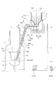
- FIG. 1 is a schematic diagram showing a processing apparatus and a workpiece input apparatus.
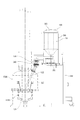
- FIG. 2 shows the second object passage and the joint part
- FIGS. 2A and 2B show the state in which the expansion pipe unit is most extended
- FIG. 2B is an outline of a side view.
- FIG. 2 and FIG. 2A are schematic views as viewed in the direction of arrow X in FIG. 2 (C) and 2 (D) show the state of the intermediate length of the telescopic pipe unit
- FIG. 2 (D) is a schematic view in side view
- FIG. 2 (C) is a view in the direction of arrow Y in FIG. 2 (D).
- FIG. 2 (E) and 2 (F) show a state in which the telescopic pipe unit is contracted
- FIG. 1 is a schematic diagram showing a processing apparatus and a workpiece input apparatus.
- FIG. 2 shows the second object passage and the joint part
- FIGS. 2A and 2B show the state in which the expansion pipe unit is most extended
- FIG. 2 (E) is a schematic view in side view
- FIG. 2 (E) is a schematic view in the Z arrow direction in FIG. 2F.
- FIG. 3 is a schematic diagram showing the processing apparatus and the workpiece input apparatus previously invented by the inventors of the present application.
- up and down is based on the up and down direction shown in FIG.
- front and rear means that the side closer to the processing apparatus F1 is the front side and the far side is the rear side in the state shown in FIG.
- Upstream / downstream is based on the passage direction (flow direction) of the workpiece S.
- the present invention is not limited to the embodiment described in this direction.
- This processing object charging apparatus 500 is a processing apparatus for processing apparatus F500 in which a furnace body (crucible) F510 for heating and melting a processing object (specifically, polycrystalline silicon (silicon nugget)) is provided. An object to be processed can be put into the furnace body F510 from outside the F500.
- a processing object specifically, polycrystalline silicon (silicon nugget)
- the workpiece input device 500 includes a workpiece storage portion (hopper) 511 that can temporarily store a workpiece, and a workpiece supplied from the workpiece storage portion 511.
- a feeder 512 for conveying is provided.
- the workpiece input device 500 includes an input device main body 510 in which a portion including the workpiece storage portion 511 and the feeder 512 is supported by a moving mechanism 550 so as to be separately movable in the vertical, front-rear, and horizontal directions.
- path 520 is the pipe-shaped part 522 made from quartz glass, Comprising: It has the pipe-shaped part 522 integrated in the longitudinal direction.
- the pipe-like portion 522 is provided so as to be directed obliquely downward as illustrated.
- the object to be processed can be put into the furnace body F510 from the outlet end 521 of the pipe-shaped portion 522.
- the workpiece passage 520 includes a drive mechanism, and can move (forward / retreat) in the longitudinal direction with respect to the furnace body F510. The retreat of the workpiece passage 520 is made so as not to interfere with the single crystal silicon when the solidified single crystal silicon is pulled up.
- a joint portion 530 is provided between the charging device main body 510 and the workpiece passage 520 so that the charging device main body 510 and the workpiece passage 520 can be separated.
- a closing portion 540 capable of blocking the workpiece passage 520 is provided downstream of the joint portion 530 (in the passage direction of the workpiece). Therefore, the object to be processed can be replenished to the object-to-be-processed container 511 by opening the lid 513 provided in the charging apparatus main body 510 with the closing part 540 closed.
- the charging device main body 510 is separated from the workpiece passage 520 with the joint portion 530 as a boundary, and the workpiece storage portion 511 is moved to a position where it can be easily operated by the moving mechanism 550. This can be done more efficiently.
- the workpiece input device 500 invented by the inventors of the present application, the workpiece can be replenished without destroying the special atmosphere inside the processing device F500.
- the unmelted object to be processed in the furnace body F510 or the object to be processed (molten metal) in the molten state jumps up to the outside of the furnace body F510. It may come out.
- the outlet end 521 of the workpiece passage 520 is placed in the furnace body F510 as much as possible regardless of whether the workpiece is thrown in before processing or additional charging (additional) during processing. It is desirable to place the object to be processed in a position close to the surface of the molten metal or the unmelted object to be processed.
- the workpiece when the workpiece is thrown in after placing the outlet end 521 of the workpiece passage 520 as close as possible to the surface of the molten metal, the workpiece may be piled up in the furnace body F510 like a mountain. . In this case, since the workpiece closes the outlet end 521 of the workpiece passage 520, the workpiece can be held in the workpiece passage 520, and the workpiece cannot be continuously charged. Further, as the workpiece is melted, the surface of the molten metal in the furnace body F510 rises, and the outlet end 521 of the workpiece passage 520 may be immersed in the molten metal.
- the workpiece passage 520 can be moved backward (moved to the upper right in the figure) with respect to the processing apparatus F500, the unmelted workpieces stacked like the mountain are stacked. And the outlet end 521 of the workpiece passage 520 are vacant so that the workpiece to be handled can be put into the furnace body F510. Further, the outlet end 521 of the workpiece passage 520 can be separated from the surface of the molten metal that has risen.
- the workpiece passage 520 has the pipe-like portion 522 integrated in the longitudinal direction. For this reason, if the workpiece path 520 is to be moved backward as described above, the entire workpiece path 520 is moved backward. That is, together with the outlet end 521 of the workpiece passage 520, the joint portion 530 at the upper end in the drawing of the workpiece passage 520 also moves obliquely upward.
- the workpiece passage 520 is left without being separated from the workpiece passage 520 as shown in the figure. Need to retreat. Therefore, it is necessary to move the charging device main body 510 in the same direction.
- the workpiece passage 520 is retracted to avoid interference with the single crystal silicon. It is premised to be performed separately from the passage 520. Then, it has not been assumed that the processing apparatus passage 520 is moved backward without separating the charging apparatus main body 510 from the processing object path 520. For this reason, the charging apparatus main body 510 does not have a configuration that can be moved in accordance with the retreat of the workpiece passage 520.
- the moving mechanism 550 can only be moved separately in the up / down, front / rear, and left / right directions as described above. For this reason, in order to retract the workpiece passage 520 without separating the charging device body 510 from the workpiece passage 520, the feeding device body 510 is moved in accordance with the diagonally upward movement of the joint portion 530. For example, it must first be moved upward and then moved backward. And since the charging device main body 510 must be moved separately upward and backward, it is not possible to increase the movement distance once. For this reason, the retreat of the workpiece passage 520 and the movement of the charging device main body 510 must be alternately performed in small increments.
- the charging device main body 510 in which the object to be processed is stored is heavy and may be about 200 kg. Therefore, it is very difficult to move the outlet end 521 of the workpiece passage 520 without separating the charging device main body 510 from the workpiece passage 520.
- the workpiece input device 500 has room for improvement in terms of workability.
- the present invention is based on the above problem.
- the processing apparatus F1 to which the workpiece input apparatus 1 according to the present embodiment is attached will be described.
- the processing apparatus F ⁇ b> 1 can be hermetically sealed, and the workpiece S can be melted in a furnace body (crucible) F ⁇ b> 11 provided as a processing unit.
- the processing apparatus F1 is used to manufacture single crystal silicon S2 that is a material of a semiconductor substrate.
- polycrystalline silicon silicon nugget
- the diameter dimension of the silicon nugget used in this embodiment is about 10 mm.
- single crystal silicon S2 is manufactured by the CZ method.
- a method of manufacturing the single crystal silicon S2 of this embodiment will be briefly described.
- the silicon nugget charged into the furnace body F11 in an inert gas atmosphere is heated to about 1800 ° C. and melted.
- Single-crystal silicon as a seed is immersed in this molten silicon (hereinafter referred to as “molten metal”) S1, and then the single-crystal silicon as a seed is slowly lifted while rotating, thereby producing a crystal. Will grow.
- molten metal molten silicon
- a single crystal silicon (ingot) S2 that is a substantially cylindrical solid is formed. That is, the processing apparatus F1 is used to pull up the single crystal silicon S2 from the molten metal S1.
- the inert gas atmosphere in the present embodiment specifically refers to an atmosphere in which the internal space of the processing apparatus F1 is once evacuated and then the internal space is filled with an inert gas such as argon or nitrogen. Therefore, a deaeration pump (vacuum pump) and an inert gas supply pipe are provided in the processing apparatus F1 (not shown). Note that the inside of the processing object input device 1 described below is also placed in the same inert gas atmosphere as that in the processing device F1 when the following closing portion 14 is not closed.
- the inside of the processing apparatus F1 may be in a vacuum atmosphere.
- the inside of the processing apparatus F1 may be in a vacuum atmosphere.
- a part of the workpiece S evaporates inside the processing apparatus F1. Since this is inconvenient in the present embodiment, an inert gas is introduced into the processing apparatus F1 in order to suppress the evaporation of silicon by the pressure of the inert gas. Note that the pressure of the inert gas introduced into the processing apparatus F1 is optimal for the type of the object to be processed S.
- the material constituting the object to be processed S is silicon, but the object to be processed S that is the object of the present invention is not limited to this.
- Various substances such as metals and resins other than silicon can be used as the workpiece S.
- the “treatment” in the present embodiment includes a series of operations from melting of the silicon nugget by heating and formation of single crystal silicon (ingot) by pulling up from the molten metal S1.
- “Processing” is a broader concept, and refers to all operations for applying various physical or chemical changes to the workpiece S in an airtight state.
- the workpiece input device 1 can input the workpiece S into the furnace body F11 from the outside of the processing device F1 into the processing device F1.
- the charging apparatus main body 1a a generic term for parts separated in the following joint part 15 and closer to the workpiece storage part 11 than the joint part 15 will be described as the charging apparatus main body 1a.
- the workpiece input device 1 includes a workpiece storage unit 11 and a transport unit 1b.
- the conveyance part 1b is a site
- the transport unit 1 b includes a workpiece passage 12 and a workpiece extraction mechanism 13.
- the transport unit 1 b includes a closing unit 14 and a joint unit 15. Details will be described later.
- the object to be processed S is conveyed from the object to be processed container 11 to the processing apparatus F1 through the object to be processed passage 12 in the conveying part 1b.
- the portion of the transport path that is touched by the workpiece S is made of quartz glass, which is a material that is resistant to wear, or is lined with quartz glass. Thereby, it is possible to suppress the possibility that impurities such as metal powder due to wear are mixed into the workpiece S as much as possible, and it is possible to manufacture single crystal silicon S2 having high purity.
- the workpiece storage unit 11, a part of the workpiece passage 12, and the workpiece extraction mechanism 13 are each provided inside a supply tank 111 made of stainless alloy. And when the to-be-processed object injection
- outside air in the description of the present embodiment refers to the atmosphere outside the workpiece input device 1 and the processing device F1.
- the supply tank 111 includes a substantially cylindrical supply tank main body 111a and a protruding portion 111b protruding from the supply tank main body 111a in the horizontal direction.
- the supply tank main body 111a and the protruding portion 111b are integrated by flange connection.
- the supply tank 111 may not be provided as described above, and a structure in which the workpiece storage unit 11 and the workpiece passage 12 are directly connected so as to maintain an airtight state with respect to the outside air may be employed.
- the supply tank main body 111a and the protrusion 111b may be integrated by welding or the like.
- the to-be-processed object accommodating part 11 is a site
- the to-be-processed object accommodating part 11 is equipped with the accommodating port 111c which can be opened and closed.
- the storage port 111c is used when the workpiece S is stored in the workpiece storage section 11.
- the accommodation port 111c can be opened and closed by the lid portion 111d.
- the hopper is used as this to-be-processed object accommodating part 11. As shown in FIG.
- the hopper 11 is provided in the supply tank 111 by laminating flat quartz glass.
- the shape of the hopper 11 is a shape in which an octagonal pyramid is connected to the lower end of an octagonal prism whose upper and lower ends are open. In the hopper 11, the lower end of the octagonal pyramid portion is opened, and the workpiece S naturally falls from that portion, and the workpiece S is taken out to the transport unit 1b.
- the hopper 11 when the hopper 11 has a shape in which an octagonal column and an octagonal pyramid are combined, the hopper 11 can be formed by combining flat-plate quartz glass whose plan view is rectangular or trapezoidal. Therefore, the hopper 11 can be easily manufactured, and the manufacturing cost of the hopper 11 can be suppressed.
- the shape of the to-be-processed object accommodating part 11 of this invention is not restricted to the shape which combined the octagonal column and the octagonal pyramid like the hopper of this embodiment, Other polygonal columns and a polygonal pyramid are combined. It may be a combined shape.
- a cylindrical shape may be adopted depending on circumstances.
- the lid portion 111d in the present embodiment is provided at the upper end portion of the supply tank main body 111a so as to maintain an airtight state with respect to the outside air. By removing the lid portion 111d from the supply tank main body 111a, the accommodation port 111c can be opened, and the workpiece S can be replenished to the hopper 11.
- path 12 is a site
- the upstream end of the workpiece passage 12 is provided at a position where the workpiece S can be received from the hopper 11.
- path 12 is provided in the position which can throw in the to-be-processed object S inside the processing apparatus F1. More specifically, the downstream end 12a in the workpiece passage 12 is located inside the processing apparatus F1 and above the furnace body F11.
- the workpiece passage 12 of the present embodiment includes a first workpiece passage 121 located on the hopper 11 side and a second workpiece passage 122 located on the processing apparatus F1 side. And the 1st to-be-processed object channel
- path 122 can be isolate
- the downstream end 12a of the workpiece passage 12 belongs to the second workpiece passage 122 (more specifically, the second pipe 122b).
- the second workpiece passage 122 is not separated from the processing apparatus F1 except when the first pipe 122a and the second pipe 122b (described later) are replaced.
- the movement mechanism 2 (described later) only needs to be able to move the first workpiece passage 121 and does not need to bear the movement of the second workpiece passage 122. That is, the design of the moving mechanism 2 can be simplified because the workpiece passage 12 includes the first workpiece passage 121 and the second workpiece passage 122 as described above.
- path 12 and the hopper 11 are provided in the positional relationship which can convey the to-be-processed object S, without making outside air contact.
- the hopper 11 is formed inside the supply tank 111, and the first workpiece passage 121 is formed below the supply tank 111. For this reason, it is possible to convey the workpiece S without touching the outside air.
- the first workpiece passage 121 is a portion that extends horizontally from directly under the hopper 11 to the front. And this 1st to-be-processed object channel
- path 121 exists over the lower part of the supply tank main body 111a, and the protrusion part 111b which protruded ahead from the lower part of this supply tank main body 111a.
- An enlarged portion 122a1 (described later) of the first pipe 122a is located on the downstream side of the protruding portion 111b, and the workpiece S enters from the enlarged portion 122a1 and is conveyed to the second workpiece passage 122. It will be done.
- the second object passage 122 is connected to the downstream end of the first object passage 121 through the joint portion 15 so that the object S can pass. And the 2nd to-be-processed object channel
- path 122 is arrange
- a part of the second workpiece passage 122 enters the first workpiece passage 121.
- the downstream end of the first workpiece passage 121 and the upstream end of the second workpiece passage 122 may be provided in an overlapping manner.
- the second object passage 122 of the present embodiment has a pipe unit (expandable pipe unit) 122x formed by combining a first pipe 122a and a second pipe 122b arranged on the same axis. That is, the telescopic pipe unit 122x constitutes a part of the workpiece passage 12. Both the first pipe 122a and the second pipe 122b are made of quartz glass. The outer diameter (excluding the enlarged portion 122a1) of the first pipe 122a is smaller than the inner diameter (excluding the enlarged portion 122b1) of the second pipe 122b. Accordingly, the first pipe 122a (insertion side pipe) can be inserted into the second pipe 122b (insertion side pipe).
- the expansion and contraction pipe unit 122x can be expanded and contracted in the longitudinal direction according to the degree of insertion or the distance between the pipes 122a and 122b that are not inserted (the total length of the expansion and contraction pipe unit 122x can be changed). it can). During the expansion and contraction, the downstream end 122b2 of the second pipe 122b approaches and separates from the upstream end of the first pipe 122a.
- the upstream end portion of the first pipe 122a is a pipe inlet end serving as an inlet of the workpiece S, and has an enlarged portion 122a1 whose diameter is increased toward the tip.
- the enlarged portion 122 a 1 is positioned below the downstream end of the trough 132 of the workpiece extraction mechanism (electromagnetic vibration feeder) 13.
- the enlarged portion 122a1 is a portion that receives the workpiece S conveyed on the trough 132 and guides it into the first pipe 122a.
- the downstream end 122a2 of the first pipe 122a is cut by a cross section orthogonal to the longitudinal direction of the first pipe 122a.
- the downstream end 122a2 is a portion that is inserted into the second pipe 122b when the telescopic pipe unit 122x contracts.
- the upstream end portion of the second pipe 122b has an enlarged portion 122b1 whose diameter is increased toward the tip.
- the enlarged portion 122b1 is a portion for attaching the second pipe 122b to the second pipe support portion 16 connected to a drive plate 175 (described later) of the passage moving mechanism 17.
- the enlarged portion 122b1 can also serve as a guide for guiding the downstream end 122a2 of the first pipe 122a when the first pipe 122a is inserted into the second pipe 122b.
- a closing portion 14 (described later) is provided above the enlarged portion 122b1.
- the closing portion 14 is integral with the second pipe 122b.
- downstream end 122b2 of the second pipe 122b (coincident with the downstream end 12a of the workpiece passage 12) is a pipe outlet end serving as the outlet of the workpiece S, and coincides with the downstream end 12a of the workpiece passage 12 To do.
- the downstream end 122b2 may be cut in the horizontal direction as shown. Further, it may be cut in the vertical direction (direction parallel to the vertical line C passing through the center of the furnace body F11).
- the second workpiece passage 122 is configured as described above, as shown in FIGS. 2B, 2D, and 2F, the first workpiece in the joint portion 15 (the upper end portion in the drawing).
- the second pipe 122b is moved relative to the first pipe 122a while maintaining the joining position with the passage 121 (while the position of the pipe inlet end is fixed), and the second workpiece passage 122 is moved in the longitudinal direction.
- the expansion pipe unit 122x is expanded or contracted by insertion or by approaching / separating, the downstream end 12a of the workpiece passage 122 is approached / separated from the furnace body F11 with a relatively simple configuration. Can be made.
- FIG. 2 (B) shows a state in which the expansion pipe unit 122x is most extended.
- FIG. 2D shows a state where the expansion pipe unit 122x is slightly contracted.
- FIG. 2F shows a state where the expansion pipe unit 122x is further contracted.
- the first pipe 122a has not yet been inserted into the second pipe 122b.
- the closing part 14 can be closed.
- the closing portion 14 is opened, and the first pipe 122a is inserted into the second pipe 122b. Therefore, the first pipe 122a exists in the closing portion 14.
- the second workpiece passage 122 can have an arbitrary length within the range in which the telescopic pipe unit 122x can be expanded and contracted.
- the first pipe 122a is fixed to the processing apparatus F1 by the fixing portion 12b. Therefore, the first pipe 122a does not move with respect to the processing device F1, and the second pipe 122b moves. Therefore, the position of the downstream end 12a of the processed material passage 122 with respect to the processing apparatus F1 (more specifically, the furnace body F11) can be easily changed.
- protective bellows 12c, 12d are, for example, stainless steel thin plates formed in a bellows shape by welding or integral molding, and are expanded and contracted according to the expansion and contraction of the expansion and contraction pipe unit 122x.
- the first protective bellows 12 c exists between the lower joint member 152 and the closing portion 14 of the joint portion 15 and is hermetically connected to the lower joint member 152 and the closing portion 14.
- the second protective bellows 12d exists between the closing portion 14 and the fixing portion 12b, and is hermetically connected to the closing portion 14 and the fixing portion 12b.
- the configuration of the second workpiece passage 122 is not limited to the configuration of the present embodiment, and various modifications are possible.
- the second object passage 122 may be expanded and contracted by using a bellows-like member.
- the pipes 122a and 122b of the present embodiment are straight pipes having a constant diameter except for the enlarged portions 122a1 and 122b1, but the diameter may be changed like a tapered pipe.
- a curved tube having a predetermined curvature may be used.
- the stretchable pipe unit 122x may be configured by combining three or more pipes.
- the workpiece removal mechanism 13 is a part for transporting the workpiece S in an airtight state from the workpiece storage portion 11 to the workpiece passage 12.
- an electromagnetic vibration feeder is used as the workpiece removal mechanism 13.
- This electromagnetic vibration feeder is provided inside the first workpiece passage 121. That is, the workpiece removal mechanism 13 is provided in the transport unit 1b. Therefore, the workpiece removal mechanism 13 is not limited to the one provided inside the workpiece passage 12 as in the present embodiment, and is provided at a position away from the workpiece passage 12. It may be.
- the electromagnetic vibration feeder includes a drive unit 131 and a trough 132.
- the trough 132 can be vibrated by the drive unit 131, and the workpiece S placed on the trough 132 can be conveyed downstream.
- the trough 132 is a bowl-shaped part whose upper and downstream ends are open, and in this embodiment, quartz glass is lined on the inner surface.
- the trough 132 is provided from the position immediately below the hopper 11 to the vicinity of the downstream end of the first workpiece passage 121 along the direction in which the first workpiece passage 121 extends. As a result, the workpiece S naturally dropped from the lower end of the hopper 11 is carried on the trough 132 to the downstream side. And the to-be-processed object S which came to the downstream end of the trough 132 falls to the expansion part 122a1 of the said 1st pipe 122a.
- the workpiece S can be continuously and quantitatively introduced into the processing apparatus F1. Therefore, the processing object S can be continuously added to the furnace body F11 little by little, so that the processing efficiency and accuracy can be improved. Of course, it is possible to input a small amount of the workpiece S.
- the electromagnetic vibration feeder was used as described above. This can eliminate such a concern.
- the first workpiece passage 121 extends in the horizontal direction, and the second workpiece passage 122 is inclined obliquely downward and forward. Therefore, the workpiece S is conveyed in the horizontal direction by the electromagnetic vibration feeder in the first workpiece passage 121, and is conveyed obliquely downward in the second workpiece passage 122 by natural fall due to gravity.
- the present invention is not limited to this embodiment.
- the first workpiece passage 121 and the second workpiece passage 122 are both directed obliquely downward or downward, and both are natural due to gravity. You may convey the to-be-processed object S by dropping.
- a flow rate adjusting mechanism such as a gate or a valve provided in the lower portion of the hopper 11 serves as the workpiece extraction mechanism 13.
- the workpiece removal mechanism 13 is used to transport the workpiece S in the horizontal direction, it is not limited to the electromagnetic vibration feeder as in the present embodiment, for example, a belt conveyor or a roller conveyor.
- various transport mechanisms can be used as long as they have a function capable of transporting the workpiece S from one side to the other side.
- the conveyance direction of the workpiece S by the workpiece extraction mechanism 13 may be other than the horizontal direction.
- the closing part 14 is a part capable of blocking the processing apparatus F1 side and the workpiece storage part 11 side of the transport part 1b.
- the telescopic pipe unit 122x is provided so as to be able to block between the first pipe 122a and the second pipe 122b.
- the closing portion 14 includes an opening / closing member (valve element) (not shown) that can close the space in the closing portion 14 for the blocking.
- the closing portion 14 of the present embodiment is a gate valve provided at one location on the upper end of the second pipe 122 b in the second workpiece passage 122.
- the closing part 14 and the second pipe 122b are connected in an airtight manner.
- the closing part 14 By closing the closing part 14, the part closer to the processing device F ⁇ b> 1 than the closing part 14 can be closed in an airtight state. And by this closing part 14, the conveyance part 1b can be closed so that the to-be-processed object S may not leak.
- various valves such as a globe valve, a ball valve, and a butterfly valve can be used in addition to the gate valve if conditions permit.
- the downstream end 122a2 of the first pipe 122a in the second workpiece passage 122 is downstream of the opening / closing member when the closing portion 14 is opened, as shown in FIGS. Located on the side.
- the workpiece S is charged with the downstream end 122a2 of the first pipe 122a inserted into the second pipe 122b.
- the workpiece S passing through the second workpiece passage 122 does not touch the opening / closing member and the constituent members (O-ring, packing, etc.) that achieve the above-described blocking by being in close contact with the opening / closing member. You can Therefore, it is possible to suppress the occurrence of poor shutoff of the closed portion 14 due to the pieces of the workpiece S being caught.
- the closing portion 14 is provided at the upper end of the second pipe 122b, but is not limited thereto.
- the closing part 14 may be provided at another position in the transport part 1b.
- the closing portion 14 needs to be provided on the processing device F1 side rather than the joint portion 15 in order to maintain the airtight state of the processing device F1 after the separation. There is.
- the closing portion 14 is provided on both the processing apparatus F1 side and the charging apparatus main body 1a side with the joint portion 15 interposed therebetween. May be provided.
- the closing portion 14 By providing the closing portion 14 in this way, if the closing portion 14 is closed, the hopper 11 can be opened to the outside air while maintaining the inert gas atmosphere inside the processing apparatus F1. For this reason, it is possible to replenish the hopper 11 with the processing object S by opening the lid 111d while continuing to melt the processing object S in the furnace body F11 of the processing apparatus F1. And after replenishing the to-be-processed object S to the hopper 11, the to-be-processed object S newly replenished to the hopper 11 can be thrown in in the furnace body F11 by opening the closing part 14. FIG. When the workpiece S newly replenished to the hopper 11 is put into the furnace body F11, the hopper 11 side needs to be in an inert gas atmosphere rather than the closing portion 14.
- a joint part 15 capable of separating and joining the transport part 1 b is provided in the processing object passage 12 at a position closer to the processing object storage part 11 than the closing part 14. .
- the joint portion 15 makes it possible to separate the transport portion 1b.
- the joint portion 15 may be provided at any position of the transport portion 1b as long as the joint portion 15 is closer to the workpiece storage portion 11 than the closing portion 14. Then, as shown in FIG. 3 (A), the joint portion 15 allows the portion of the workpiece input device 1 closer to the hopper 11 than the joint portion 15 (the charging device main body 1a in this embodiment) to be the processing device F1.
- the joint portion 15 is provided between the first workpiece passage 121 and the second workpiece passage 122. More specifically, an upper joint member 151 is provided at the downstream end of the first workpiece passage 121, and the upstream end of the second workpiece passage 122 (however, the enlarged portion 122b1 of the second pipe 122b is provided). Excluding) is provided with a lower joint member 152.
- each joint member 151,152 is made into the substantially flange shape, and it can join airtightly by contact
- the closing part 14 and the joint part 15 are provided as described above, the first workpiece passage 121 and the second workpiece passage 122 of the workpiece passage 12 are divided by the joint portion 15.
- the closed portion 14 can maintain the airtight state of the downstream portion based on the moving direction of the workpiece S in the workpiece passage 12. Specifically, the following is possible. That is, if the processing object S still remains in the hopper 11 at the time when it is no longer necessary to replenish the processing object S in the processing apparatus F1, the joint portion 15, the workpiece passage 12 can be separated, and the input device main body 1a can be replaced with a treatment device F1 different from that before separation. Thereby, the to-be-processed object S remaining in the hopper 11 can be thrown into another processing apparatus F1.
- the expansion pipe unit 122x is extended to enter the first pipe 122a in the closing portion 14. Is not present, the closed portion 14 is closed, and the workpiece passage 12 is separated with the joint portion 15 as a boundary. Then, the charging device main body 1a is moved down to a convenient position by, for example, lowering the charging device main body 1a by operating the lift 21, and then the workpiece S is replenished to the hopper 11. Thereafter, the charging device main body 1a is replaced with a processing device F1 different from that before separation. However, the charging apparatus main body 1a may be attached again to the same processing apparatus F1 as before separation. In particular, when the charging device main body 1a is supported by the following lift 21, the above-described replenishing operation can be performed more efficiently.
- the charging device main body 1a can be made compact and easier to handle. . This is not applicable at any manufacturing site, but according to the present embodiment, such a selection is possible, and the device can be optimized according to the situation at the manufacturing site.
- the second workpiece passage 122 is left in the processing apparatus F1. Therefore, the separation operation of the second workpiece passage 122 with respect to the processing device F1 becomes unnecessary, and the movement of the charging device main body 1a by the following moving mechanism 2 becomes easy. Further, it is possible to reduce the possibility that the pipes 122a and 122b in the second workpiece passage 122 made of quartz glass are damaged as the charging apparatus main body 1a moves.
- path 122 can be moved separately from the 1st to-be-processed object channel
- FIG. Therefore, the downstream in the to-be-processed object channel
- the end 12a can be moved by moving only the second workpiece passage 122. Therefore, the space required for movement can be reduced, and the workpiece input device 1 can be reduced in size.
- the movement of the downstream end 12a in the workpiece passage 12 by the passage movement mechanism 17 can be performed separately from the movement by the following movement mechanism 2 (in other words, the movement mechanism 2 described below is to be processed). Since it is not necessary to take charge of the movement of the downstream end 12a in the passage 12, the structure of the moving mechanism 2 described below can be simplified, and from this point, the enlargement of the workpiece input apparatus 1 can be suppressed.
- the procedure for replenishing the workpiece S using the workpiece input apparatus 1 will be briefly summarized.
- the processing object S is being processed by the processing apparatus F1
- the processing object S in the furnace body F11 decreases, it is accommodated in the hopper 11 by the operation of the electromagnetic vibration feeder that is the processing object take-out mechanism 13.
- the to-be-processed object S is conveyed through the to-be-processed object channel
- the closing part 14 is opened and the joint part 15 is joined.
- the operator closes the closing portion 14 and then separates the joint portion 15. Thereby, the joint part 15 can be isolate
- the worker replenishes the workpiece S as described above, and then joins the joint portion 15 using the moving mechanism 2. Thereafter, by opening the closing portion 14, the workpiece S can be put into the furnace body F11.
- transduces inert gas and the inside of the injection apparatus main body 1a Use an inert gas atmosphere.
- the moving mechanism 2 which can move the input device main body 1a in the direction which approaches / separates with respect to the processing apparatus F1 is provided.
- the moving mechanism 2 of the present embodiment includes a lift 21 and a plurality of wheels 22 (a front wheel 221 and a rear wheel 222).
- the lift 21 can move the charging device main body 1a in the vertical direction.
- a manual lift that moves the input device main body 1a up and down by a handle operation by an operator is employed, but a lift driven by a motor or the like may be used.
- the wheel 22 rotates along the installation surface G on which the processing device F1 is installed, and can move the input device main body 1a and the lift 21 mainly in the front-rear direction, and the input device main body 1a and the lift 21. Can also be moved in the left-right direction.
- This moving mechanism 2 makes it easy to move the charging device main body 1a to separate and join the joint portion 15. Then, the input device main body 1a can be moved relative to the different processing device F1. Further, when the processing apparatus F1 is lowered to near the installation surface G, the replenishment of the workpiece S can be simplified. Further, as shown in FIG. 1, the processing apparatus F ⁇ b> 1 is placed at a high position, so that a portion of the processing object passage 12 that is naturally dropped due to gravity (the second processing object passage 122 in the present embodiment). The workpiece S can be transported more smoothly. Thus, by providing the moving mechanism 2, the workpiece input device 1 can be made very easy to use. Moreover, the restrictions given to the layout of the production site can be made small.
- the position of the downstream end 12a in the workpiece passage 12 with respect to the processing apparatus F1 can be moved.
- the movement of the downstream end 12a is movable between the position of the central area, which is a wide area including the vertical line C passing through the center of the furnace body F11, and the position outside the central area.
- the “central region” means a region where the single crystal silicon S2 can be pulled up, excluding the peripheral portion of the furnace body F11. More specifically, in the present embodiment, the movement of the downstream end 12a is a direction of approaching / separating with respect to the vertical line C passing through the center of the furnace body F11.
- the pipe 122b moves relative to the processing device F1 (more specifically, the furnace body F11). The movement of the second pipe 122b is performed separately from the movement of the first workpiece passage 121.
- the most forward portion of the downstream end 12a in the workpiece passage 12 is in the vicinity of the vertical line C (the most forward portion of the downstream end 12a is the central portion).
- the most forward portion of the downstream end 12a is positioned on the inner side of the upward movement trajectory S2a of the single crystal silicon S2.
- the most forward portion of the downstream end 12a is more than the movement locus S2a. Is also performed so as to be located outside.
- the processing object passage 12 is positioned approximately at the center of the furnace body F11.
- the workpiece S can be input. That is, compared with what throws in the to-be-processed object S outside movement locus
- the workpiece S can be introduced from the workpiece passage 12 to a position closer to the center of the furnace body F11, the workpiece S is not easily biased in the furnace body, and the silicon granules placed in the furnace body Is uniformly heated and can be efficiently melted. Therefore, the pulling operation of single crystal silicon can be performed smoothly and the manufacturing efficiency is good. And since the to-be-processed object S before a fusion
- the single crystal silicon S2 can be pulled up from the furnace body F11.
- downstream end 122b2 of the second pipe 122b is cut and opened along a plane parallel to the vertical line C passing through the center of the furnace body F11, the downstream end 122b2 is downstream of the vertical line C.
- the end 12a is approaching (when the downstream end 12a is at the position of the central region), if the downstream end 12a overlaps the vertical line C, at least the radius of the movement locus S2a of the single crystal silicon S2 If the second pipe 122b is moved by this distance, interference between the single crystal silicon S2 pulled up from the furnace body F11 and the second pipe 122b can be avoided. That is, the moving distance of the second pipe 122b can be minimized.
- the workpiece input apparatus 1 includes a passage moving mechanism 17.
- the second pipe 122b is moved in the longitudinal direction by the passage moving mechanism 17, and moves into and out of the processing apparatus F1 along with this movement.
- the first pipe 122a can be inserted into the second pipe 122b, depending on the degree of insertion of the first pipe 122a or the distance between the pipes 122a and 122b that are not inserted.
- the telescopic pipe unit 122x can be expanded and contracted.
- the 2nd pipe 122b can be made to go in and out with respect to the processing apparatus F1, maintaining the joining position in the joint part 15, and the 2nd to-be-processed object channel
- path 122 can be expanded-contracted in a longitudinal direction.
- the downstream end 12a of the workpiece passage 12 is arranged as close as possible to the surface of the molten metal S1 in the furnace body F11 or to the unmelted workpiece S, the unmelted workpiece that has already been put in.
- the object S may be piled up in the furnace body F ⁇ b> 11 like a mountain, and the downstream object 12 may be caught in the second object path 122 by closing the downstream end 12 a of the second object path 122. .
- the second processing object passage 122 is moved backward with respect to the processing apparatus F1, so that the processing object S can be introduced from the processing object storage portion 11 and stacked like the mountain.
- the space between the workpiece S and the downstream end 12a of the second workpiece passage 122 can be increased.
- the to-be-processed object S can be thrown in in the furnace body F11 also in the said case. Further, as the workpiece S melts, the surface of the molten metal in the furnace body F11 rises, and the downstream end 12a of the second workpiece passage 122 may be immersed in the molten metal. Even in this case, the downstream end 12a of the second workpiece passage 122 can be separated from the surface of the molten metal by moving the second workpiece passage 122 backward with respect to the processing apparatus F1.
- the passage moving mechanism 17 in the present embodiment will be described in more detail.
- the passage moving mechanism 17 includes a frame 171, a support shaft 172, a drive shaft 173, a driven portion 174, and a drive plate 175.
- the frame 171 is a portion fixed directly or indirectly to the processing device F1, and is immobile with respect to the processing device F1.
- the fixed plate 171a is fixed to the processing apparatus F1 at a position downstream of the frame 171.
- the support shaft 172 is fixed to the frame 171.
- the support shaft 172 is a round bar provided in parallel with the longitudinal direction of the second pipe 122b.
- a drive shaft 173 is provided at a position on the opposite side of the frame 171 that is parallel to the support shaft 172 and sandwiches the second pipe 122b.
- a driven portion 174 is rotatably provided on the side of the frame 171 close to the drive shaft 173.
- the rotational axis of the driven portion 174 is orthogonal to the drive shaft 173.
- the drive shaft 173 is a round bar having a screw on the outer peripheral surface, and is rotatable with respect to the frame 171 in the circumferential direction.
- a bevel gear 173 a is attached to the downstream end of the drive shaft 173.
- the bevel gear 173 a meshes with a bevel gear 174 a that is also provided at the end of the driven portion 174. Therefore, the drive shaft 173 can be rotated with the rotation of the driven portion 174.
- the driven portion 174 may be automatically operated by connecting a driving means such as a motor, or may be manually operated by attaching a handle.
- the driving plate 175 is connected to the second pipe support portion 16 and supports the second pipe 122b immovably.
- a support shaft 172 and a drive shaft 173 are attached to the drive plate 175 so as to penetrate therethrough. This penetration is slidable with respect to the support shaft 172 and can be screwed with the drive shaft 173.
- the drive plate 175 can be moved toward and away from the fixed plate 171a in accordance with the rotation of the drive shaft 173 by the operation of the driven portion 174.
- the second pipe 122b approaches the vertical line C passing through the center of the furnace body F11, and is closest to the front among the downstream ends 12a. This part moves to the position of the central region.
- the second pipe 122b When the drive plate 175 moves away from the fixed plate 171a, the second pipe 122b is separated from the vertical line C, and the most forward portion of the downstream end 12a is located outside the central region. Moving. As described above, since the first pipe 122a and the second pipe 122b expand and contract in combination, the position of the joint portion 15 is maintained without change.
- the position of the second pipe 122b with respect to the processing apparatus F1 can be freely set as long as it is within the movement range of the drive plate 175. Therefore, the input position of the workpiece S with respect to the furnace body F11 can be set freely. Moreover, as described above, since the position of the joint portion 15 is maintained without change, the second pipe 122b can be moved while the charging device main body 1a is connected.
- At least one of the joint members 151 and 152 in the joint portion 15 may include a guide portion, and the other may include a guided portion.
- the guiding portion and the guided portion are configured to be in a joined state by guiding the guided portion to the guiding portion when the joint members 151 and 152 are to be joined. It is a site where alignment to the bonded state is performed. By doing in this way, since a to-be-guided part is guided to a guidance part and joint part 15 is aligned to a predetermined position, joint work can be performed easily.
- the workpiece input device 1 may be provided with a stopper as a positioning portion that restricts the movement mechanism 2 from moving in directions other than up and down. Specifically, among the plurality of wheels 22, at least a front wheel 221 is prevented from rotating in the forward direction, and a stopper for determining the position of the front wheel 221 in the left-right direction with respect to the processing device F1 is provided on the installation surface G. It can be considered to be fixed. By providing the stopper in this way, the joint portion 15 can be easily joined.
Landscapes
- Engineering & Computer Science (AREA)
- Mechanical Engineering (AREA)
- General Engineering & Computer Science (AREA)
- Crystals, And After-Treatments Of Crystals (AREA)
- Feeding, Discharge, Calcimining, Fusing, And Gas-Generation Devices (AREA)
Abstract
Priority Applications (3)
| Application Number | Priority Date | Filing Date | Title |
|---|---|---|---|
| KR1020127003052A KR20130140532A (ko) | 2011-03-09 | 2011-10-20 | 피처리물 투입 장치, 피처리물 투입 장치용의 파이프 유닛 및 이 파이프 유닛에 사용하는 파이프 |
| CN201180003886XA CN103026160A (zh) | 2011-03-09 | 2011-10-20 | 被处理物投入装置、被处理物投入装置用的管道单元及该管道单元所用的管道 |
| US13/420,297 US8684151B2 (en) | 2011-03-09 | 2012-03-14 | Raw material loading apparatus and pipe unit for raw material loading apparatus |
Applications Claiming Priority (4)
| Application Number | Priority Date | Filing Date | Title |
|---|---|---|---|
| JP2011-051806 | 2011-03-09 | ||
| JP2011051807A JP2012189244A (ja) | 2011-03-09 | 2011-03-09 | 被処理物投入装置用のパイプユニット及びこのパイプユニットに用いるパイプ |
| JP2011-051807 | 2011-03-09 | ||
| JP2011051806A JP2012189243A (ja) | 2011-03-09 | 2011-03-09 | 被処理物投入装置 |
Related Child Applications (1)
| Application Number | Title | Priority Date | Filing Date |
|---|---|---|---|
| US13/420,297 Continuation US8684151B2 (en) | 2011-03-09 | 2012-03-14 | Raw material loading apparatus and pipe unit for raw material loading apparatus |
Publications (1)
| Publication Number | Publication Date |
|---|---|
| WO2012120723A1 true WO2012120723A1 (fr) | 2012-09-13 |
Family
ID=46797707
Family Applications (1)
| Application Number | Title | Priority Date | Filing Date |
|---|---|---|---|
| PCT/JP2011/074151 Ceased WO2012120723A1 (fr) | 2011-03-09 | 2011-10-20 | Dispositif d'introduction d'objet à traiter, unité de tube pour dispositif d'introduction d'objet à traiter, et tube utilisé dans cette unité de tube |
Country Status (4)
| Country | Link |
|---|---|
| KR (1) | KR20130140532A (fr) |
| CN (1) | CN103026160A (fr) |
| TW (1) | TW201236947A (fr) |
| WO (1) | WO2012120723A1 (fr) |
Cited By (1)
| Publication number | Priority date | Publication date | Assignee | Title |
|---|---|---|---|---|
| EP4006472A1 (fr) * | 2020-11-30 | 2022-06-01 | Jinko Solar Co., Ltd | Four monocristallin |
Families Citing this family (5)
| Publication number | Priority date | Publication date | Assignee | Title |
|---|---|---|---|---|
| CN103451722A (zh) * | 2013-08-06 | 2013-12-18 | 浙江晶盛机电股份有限公司 | 能供多炉台共用的外部连续投料装置 |
| CN104947186A (zh) * | 2015-07-16 | 2015-09-30 | 江苏协鑫软控设备科技发展有限公司 | 可移动的多晶铸锭炉二次加料装置 |
| WO2018003386A1 (fr) * | 2016-06-29 | 2018-01-04 | 株式会社クリスタルシステム | Appareil de production d'un monocristal et procédé de production d'un monocristal |
| CN109306514B (zh) * | 2017-07-27 | 2021-06-08 | 隆基绿能科技股份有限公司 | 物料供给装置及晶体生长系统 |
| CN113148685A (zh) * | 2021-04-29 | 2021-07-23 | 广州柏创机电设备有限公司 | 一种自动加料器 |
Citations (3)
| Publication number | Priority date | Publication date | Assignee | Title |
|---|---|---|---|---|
| JPS5855539A (ja) * | 1981-09-28 | 1983-04-01 | Daido Steel Co Ltd | 精錬装置 |
| JPS62181894U (fr) * | 1986-05-12 | 1987-11-18 | ||
| JPH0712897U (ja) * | 1993-07-29 | 1995-03-03 | 神鋼電機株式会社 | 真空誘導溶解炉における材料供給装置 |
Family Cites Families (4)
| Publication number | Priority date | Publication date | Assignee | Title |
|---|---|---|---|---|
| US3628676A (en) * | 1970-05-06 | 1971-12-21 | Koppers Co Inc | Coal feeding system for mechanical feed-type larry car |
| JPS58183499U (ja) * | 1982-05-28 | 1983-12-07 | 昭和電工株式会社 | 電気炉投原装置 |
| JPS59115736A (ja) * | 1982-12-23 | 1984-07-04 | Toshiba Corp | シリコン顆粒供給装置 |
| CN201083464Y (zh) * | 2007-09-04 | 2008-07-09 | 江苏沙钢集团淮钢特钢有限公司 | 炼钢合金输料装置 |
-
2011
- 2011-10-20 CN CN201180003886XA patent/CN103026160A/zh active Pending
- 2011-10-20 WO PCT/JP2011/074151 patent/WO2012120723A1/fr not_active Ceased
- 2011-10-20 KR KR1020127003052A patent/KR20130140532A/ko not_active Withdrawn
- 2011-10-21 TW TW100138320A patent/TW201236947A/zh unknown
Patent Citations (3)
| Publication number | Priority date | Publication date | Assignee | Title |
|---|---|---|---|---|
| JPS5855539A (ja) * | 1981-09-28 | 1983-04-01 | Daido Steel Co Ltd | 精錬装置 |
| JPS62181894U (fr) * | 1986-05-12 | 1987-11-18 | ||
| JPH0712897U (ja) * | 1993-07-29 | 1995-03-03 | 神鋼電機株式会社 | 真空誘導溶解炉における材料供給装置 |
Cited By (2)
| Publication number | Priority date | Publication date | Assignee | Title |
|---|---|---|---|---|
| EP4006472A1 (fr) * | 2020-11-30 | 2022-06-01 | Jinko Solar Co., Ltd | Four monocristallin |
| US11795570B2 (en) | 2020-11-30 | 2023-10-24 | Jinko Solar Co., Ltd. | Single crystal furnace |
Also Published As
| Publication number | Publication date |
|---|---|
| TW201236947A (en) | 2012-09-16 |
| CN103026160A (zh) | 2013-04-03 |
| KR20130140532A (ko) | 2013-12-24 |
Similar Documents
| Publication | Publication Date | Title |
|---|---|---|
| CN102510989B (zh) | 被处理物投入装置 | |
| WO2012120723A1 (fr) | Dispositif d'introduction d'objet à traiter, unité de tube pour dispositif d'introduction d'objet à traiter, et tube utilisé dans cette unité de tube | |
| US8684151B2 (en) | Raw material loading apparatus and pipe unit for raw material loading apparatus | |
| US20110036860A1 (en) | Single-crystal growth apparatus and raw-material supply method | |
| CN102159345B (zh) | 用于在初始启动时密封铸锭的方法和设备 | |
| WO2012074934A1 (fr) | Système et procédé de fusion et de moulage par de coulée d'une charge d'alimentation | |
| JP5682808B2 (ja) | 被処理物投入装置 | |
| US7484549B2 (en) | Continuous casting of reactionary metals using a glass covering | |
| JP2012189243A (ja) | 被処理物投入装置 | |
| CN207091550U (zh) | 一种物料供给装置与晶体生长系统 | |
| CN109306516A (zh) | 物料供给装置与晶体生长系统 | |
| JP2012189244A (ja) | 被処理物投入装置用のパイプユニット及びこのパイプユニットに用いるパイプ | |
| JP2019152414A (ja) | 被処理物投入装置 | |
| CN207091546U (zh) | 物料供给设备与晶体生长系统 | |
| JP6128408B2 (ja) | 被処理物投入装置 | |
| JP2013083389A (ja) | 被処理物投入装置 | |
| CN114561689A (zh) | 加料管、单晶生长设备及其加料方法 | |
| CN109306514B (zh) | 物料供给装置及晶体生长系统 | |
| CN207435581U (zh) | 一种物料供给装置以及晶体生长系统 | |
| KR102694378B1 (ko) | 반응성 합금 및 금속을 위한 밀봉식 경사 주입 전기 유도 로 | |
| CN217556346U (zh) | 加料管和具有其的单晶生长设备 | |
| WO2023185038A1 (fr) | Appareil de réalimentation en matières premières en vue de la fabrication de monocristaux, et appareil de fabrication de monocristaux le comprenant | |
| WO2023185036A1 (fr) | Dispositif de réintroduction de matière première et dispositif de fabrication de monocristal le comprenant | |
| CN101835710A (zh) | 硅制造装置和方法 | |
| CN115012034A (zh) | 一种拉晶生产设备和拉晶方法 |
Legal Events
| Date | Code | Title | Description |
|---|---|---|---|
| WWE | Wipo information: entry into national phase |
Ref document number: 201180003886.X Country of ref document: CN |
|
| ENP | Entry into the national phase |
Ref document number: 20127003052 Country of ref document: KR Kind code of ref document: A |
|
| 121 | Ep: the epo has been informed by wipo that ep was designated in this application |
Ref document number: 11860478 Country of ref document: EP Kind code of ref document: A1 |
|
| NENP | Non-entry into the national phase |
Ref country code: DE |
|
| 32PN | Ep: public notification in the ep bulletin as address of the adressee cannot be established |
Free format text: NOTING OF LOSS OF RIGHTS PURSUANT TO RULE 112(1) EPC (EPO FORM 1205A DATED 11/12/2013) |
|
| 122 | Ep: pct application non-entry in european phase |
Ref document number: 11860478 Country of ref document: EP Kind code of ref document: A1 |